
Peco TH170 HEAT PUMP THERMOSTAT
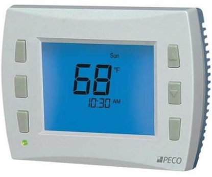
Preinstallation Considerations
Thermostat Location – The thermostat should be used indoors only. It should be mounted on an inner wall 48” from the floor, in a location with freely circulating air, and where it will be responsive to changes in room temperature. Avoid mounting near heat-generating appliances (i.e. TV, heater, refrigerator), or in direct sunlight.
Humidifiers – The humidify output connects directly to 24VAC-operated humidifiers. No other connection or interlock is required. Several installer-selectable operating modes are available as described in the Humidity Control Operation Section.
Dehumidifiers – The dehumidifier output connects to the dehumidifier input on variable–speed furnaces and fan coils. Additional dehumidification is done by controlling the compressor. Several installer-selectable operating modes are available as described in the Humidity Control Operation Section.
Outdoor Temperature Sensor – The use of an outdoor temperature in conjunction with the TH170 will improve the performance and increase the number of humidity control modes available to the installer. Run two wires from the TH170 to an outdoor location. The outdoor sensor can be mounted to the outdoor unit and existing control wires may be used for its connection.
Applications and features
Heat Pump Thermostat for 24 VAC Applications
- Up to 3 Heat and 2 Cool Stages
- System Selection: Off-Heat-Cool-Auto-Setback-Aux Heat
- Up to 2 Fan Stages: On-Auto (1 fan), Hi-Low-Auto (2 fans)
- Dehumidification/Humidity Control*
- Setback and Off-Override Capable
Also Configurable With
- Outdoor Air Sensors
- Remote Probes
- Occupancy Control Systems
- Outside Air Ecomomizer (Damper Control)
WARNING
- READ THESE INSTRUCTIONS CAREFULLY BEFORE ATTEMPTING TO INSTALL, OPERATE OR SERVICE THIS THERMOSTAT.
- Failure to observe safety information and comply with instructions could result in PERSONAL INJURY, DEATH AND/OR PROPERTY DAMAGE.
- To avoid electrical shock or damage to equipment, disconnect power before installing or servicing and use only wiring with insulation rated for full thermostat operating voltage.
- Before installing this control, the Voltage Selection Switch must be placed in the correct position. See instructions.
- To avoid potential fire and/or explosion do not use in potentially flammable or explosive atmospheres.
- Retain these instructions for future reference. This product, when installed, will be part of an engineered system whose specifications and performance characteristics are not designed or controlled by PECO.
- You must review your application and national and local codes to assure that your installation
will be functional and safe
CAUTION
- Use copper wire only, insulate or wire nut all unused leads.
- Care should be used to avoid electrostatic discharge to the T170 thermostat.
- This unit has configuration jumpers. You may need to reconfigure this thermostat for your application
Specifications
- Temperature Set Point Range 50 to 90°F / 10 to 32°C
RH Set Point Range Humidity: 20-45% RH, Dehumid - ification: 50-90% RH
- Electrical Rating 24 VAC Input, 24 VAC Output, Hardwired
- Memory – Back-Up EEPROM, No batteries required, Stores settings for unlimited time.
- Mounting Installs on standard 4” x 4” device box with a 2” x 4” horizontal mud ring
- Humidity Accuracy +/- 3% RH
- Storage Temperature Range -20 to 130°F
- Physical Dimensions 4.4”H x 5.8”W x 1.1”D
- Agency Approvals UL, UL Canada
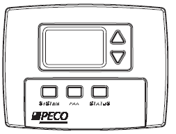
INSTALLATION
- Turn off power to thermostat at main fuse or circuit breaker box. Ensure that ALL power is disconnected. To prevent electrical shock and /or equipment damage, disconnect electrical power to the system at the main fuse or circuit breaker until installation is complete.
- Remove the front cover of old thermostat. With wires still attached, remove wall plate from the wall. If the old thermostat has a wall mounting plate, remove the thermostat and the wall mounting plate as an assembly.
- Before removing wires from old thermostat, label each wire with the terminal designation from which it was attached.
- Disconnect the wires from the old thermostat one at a time. Do not let wires fall back into the wall
Attention: Mercury Notice
This product does not contain mercury. However, this product may replace a product that contains mercury. Mercury and products containing mercury must not be discarded in household trash. Do not touch any spilled mercury. Wearing non-absorbent gloves, clean up any spilled mercury and place in a sealed container. For proper disposal of a product containing mercury or a sealed container of spilled mercury, contact your local hazardous waste center
Jumper and Circuit Board Selections
JP1 Jumper Selection – Remote Temperature Sensor: Removal of this jumper allows the temperature sensor to be located in a remote location. Accessory sensors are available in standard 60” lengths but can be extended to meet application requirements. When running probe beyond 60” care should be taken to avoid sources of EMF The remote probe input can be used with a condensate overflow switch (CO), either in conjunction with a remote probe (normally closed CO switch) or with local sensing (normally open CO switch). When the condensate switch activates, the T170 will display the service wrench and disable all outputs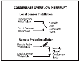
JP3 Jumper Selection – HVAC Setback Systems: This jumper is shipped in the open position to allow for Setback Operation. Placement of a jumper allows for Occupancy Detection and Door Switch Only
Operation. See Choice Below
- Setback Operation (Remove JP3): When installed, the TH170 Heating and cooling setback limits are used as temperature control points. Fan operation in the setback is cycled with demand.
- Pressing any button will override the setback for 1 hour. The setback will override any user setting except if the control is turned OFF.
- Units with an off-override factory setting will override the OFF setting.
- Intelligent Occupancy Sensors like the SD200-001 and SD200-002 can be used with this input to set the HVAC system to control at setback limits.
- Occupancy Detection (Install JP3): The TH170 can be used with PECO S200 series occupancy detection equipment.
- The occupancy and door switch inputs are designed to connect to the SB200 slave sensor and SE200 door switch.
- The Occupancy Sensor is a low-level switch that is open when there is occupancy and closed when unoccupied.
- The Door Switch is a low-level switch that is open when the door is open and closed when the door is closed.
- This system requires both an Occupancy Sensor and a Door Switch.
- Door Switch Only Operation (Install JP3): A stand-alone door switch can be connected to the TH170 to disable the HVAC system if the door is left open for more than 2 minutes.
- A one-time ten-minute override can be initiated by pressing any thermostat key.
JP4 Jumper Selection – Unused
Mounting Thermostat
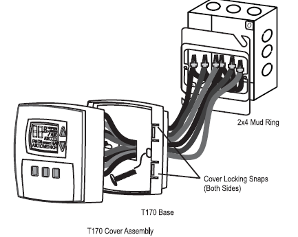
- The thermostat mounts to a 4” x 4” box with a 2” x 4” mud ring mounted horizontally (see diagram).
- Pull wires through the hole of the thermostat base.
- Mount the thermostat base to the wall using the enclosed mounting screws. Tighten screws evenly but do not over-tighten.
- Verify that the circuit board is firmly snapped into the cover and has not been dislodged during handling.
- Match and connect equipment wire thermostats using the appropriate wiring schematic as shown in the diagram.
- Wire nut all unused wires or terminate properly according to local building codes.
- Push excess wire into wall and plug the hole with a fire-resistant material (such as fiberglass insulation) to prevent drafts from affecting thermostat operation.
- Install the cover assembly. Firmly press the cover to engage the cover locking snaps. Should the cover need to be removed in the future, use a flat-edged tool to put pressure on the base sides. This will release the four side latches.
- Turn on the power to the equipment
WIRING DIAGRAM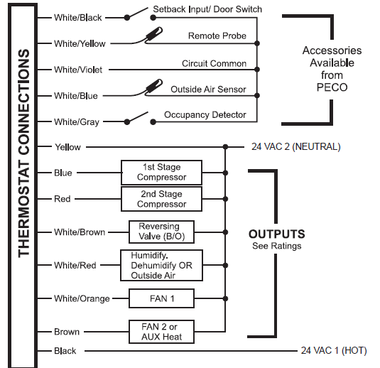
Inputs
- L1 and L2 Power Input – Both sides of the external power supply for the thermostat and controlled devices.
- Outside Air Temperature Sensor (Optional) – This input will connect to a PECO standard 10K thermistor.
- Zone Temperature Remote Probe Input / Condensate Overflow (Optional) – This input will connect to a 10K thermistor. A low level switch may also be connected to this input with or without the thermistor. Switch closure indicates overflow.
- Occupancy Sensor Input (Optional) – The Occupancy sensor is a low-level switch that is open when occupied and closed when unoccupied.
- Door Switch / Setback Input (Optional) – This input is assigned to Door Switch when jumper JP3 is placed. The Door Switch is a low-level switch that is open when the door is open and closed when the door is closed. This input is assigned to Setback when jumper JP3 is removed. The Setback input sensor is a low-level switch that is closed to signal Setback and open for normal operation.
- Relative Humidity Input (Optional) – This input is connected to a separate humidity transducer on the circuit board (not shown in the wiring diagram), that provides a DC signal to indicate the relative humidity.
Outputs
- Each output is connected to the L1 connection when enabled. Each output device is returned to the L2 connection.
- Y1 First Stage Compressor – Output cycles with an Active Demand for Heating or Cooling and disables when an Active Demand seizes.
- Y2 Second Stage Compressor – Output is enabled if an active demand has been present for a minimum of 10 minutes and the temperature is equal to or greater than 2°F from the Set Point. The 2nd
- Compressor Stage can only be enabled or disabled if 1st
Compressor Stage is enabled.
- Reversing Valve – This output is enabled with an Active Demand for Cooling and disabled with an Active Demand for Heating. Default setting can be changed in the Service Menu 11 to reverse the logic.
- Dehumidification / Humidification / Outside Air – This output can be configured for Dehumidification, Humidification, or Outside Air operation. A humidity sensor module must be connected to the PCBA for the humidity control to function. If you are installing a TH70-001, only the Outside Air Economizer feature is available.
- Fan or Fan Low – This output is enabled by manual user selection or through Auto Fan Selection microprocessor operation. The Fan is enabled either continuously or with active demand. When Fan High is an available selection and is enabled, this output is disabled.
- Fan High or Aux Heat – This output can be configured for either Fan High or Aux Heat through the service menu. Default is Aux Heat. When the system is operating in AUTO mode, the Aux Heat output is enabled when the room temperature is equal to or greater than 3°F from the temperature Set Point and after the time delay is met in Service Menu 18. Fan High is selected by manual user selection or through
- Auto Fan Selection. The Fan High is enabled either continuously or with active demand
DESCRIPTION
| DESCRIPTION | ||||
| Y1 | 1st Stage Compressor | |||
| Y2 | 2nd Stage Compressor | |||
| O | Reversing Valve | |||
| H | Provides Humidification, Dehumidification, or Outside Air based on configuration | |||
| G | Fan | OR | G1 | Fan Lo |
| W | Aux. Heat | G2 | Fan High | |
System Check-Out
- After wiring and installation is complete, energize the system.
- Set fan to ON. Select each fan speed (if available) to verify operation.
- Set the System button to AUTO, or available selection.
- Using the UP arrow, adjust temperature more than 5°F above the current room temperature to cycle on heating.
- Using the DOWN arrow adjust the Set Point to 5°F below current room temperature to cycle on cooling
THERMOSTAT CONFIGURATION / SERVICE MENU
- Please refer to page 6 for service menu table.
- To enter the Service Menu press the UP and DOWN arrows simultaneously for five (5) seconds. The current display icon will turn off and Service Menu 1 will be displayed.
- Push the SYSTEM button to move through Service Menu items 1-22.
- The UP and DOWN arrow keys will scroll through the range of options for each Service Menu feature. The selection that is flashing is the one you are selecting.
- All changes to the Service Menu are automatically saved when the system times out.
USER OPERATION
- Room Temperature and Adjustable Set Point (desired) Temperatures
- Unless adjusted in the Service Menu, the thermostat will show the current room temperature on the display.
- To show the current Set Point Value (desired room temperature), press either the UP or DOWN arrow keys.
- The initial power-up Set Point is 72° F. This value can be adjusted using the arrows keys.
- Adjustments to the Set Points are stored in the non-volatile memory, and are used for subsequent power ups.
System Switch Operation (SYS)
- OFF: All thermostat outputs are disabled.
- HEAT: Operates as a Heating only thermostat.
- COOL: Operates as a Cooling only thermostat.
- AUTO: The thermostat automatically selects between Heat ing or Cooling mode depending upon the Set Point (Desired Temp) and Zone Temperature (Actual
- Temp). The appropriate HEAT or COOL icon is enabled if demand exists.
- SETBACK: An energy saving feature that minimizes heating and cooling when the room is not occupied. The thermostat will control to the SETBACK Heat and Cool Set Points, rather than the standard Set Points. When in SETBACK, the display will show the room temperature along with the SETBACK icon. Key presses will have no effect on the Setback operation except for the System Switch Selection button, which allows the user to exit the SETBACK mode.
- AUX HEAT: For emergency heating applications, when the occupant wants only the Auxiliary Heat Source to operate. The heat pump does not operate in this mode
Fan Operation
- If the Heat Pump operates with 1 Fan Speed, occupants can choose either FAN ON or FAN AUTO.
- With FAN ON selection, the Fan is on continuously, even when no heating or cooling is required.
- With FAN AUTO selection, the Fan is on only with active demand.
- If the Heat Pump operates with 2 Fan Speeds, occupants can choose: FAN LO, FAN HI, or FAN AUTO.
- With FAN LO selection, the fan is on continuously at the fan low speed.
- With FAN HI selection, the fan is on continuously at the fan high speed.
- With FAN AUTO selection, the thermostat selects the fan speed and enables the appropriate output according to how far the room is away from the desired Set Point. Fan Low operates between Set Point and
- Fan High. Fan High is enabled 2°F from desired Set Point (configurable via Service Menu 12 Fan Stage Separation) and is disabled 1°F from the desired Set Point.
Sensor Readings – STATUS Button
- Outside Air (OA) Temperature – Push the Status Button to read value. If a Sensor is connected, the current sensed temperature will be displayed in the digits along with the OUTSIDE icon. If the OA input is closed the unit will display F1 in the digits as an indication that the filter needs to be changed. If this input is open the unit will skip over OUTSIDE and go directly to the display of %RH.
- Relative Humidity (RH) – If a humidity sensor is installed, the % RH will be displayed by pushing the Status Button. Pressing the UP or DOWN button will display the current %RH desired Set Point and will allow the operator to adjust this value. The SP range for Humidity is 20-45%RH and Dehumidification is 50
90%RH. - Selection of Humidify or Dehumidify must be made in Service Menu 12 to allow the adjustment of %RH Set Point. If Outside Air operation is selected from Service Menu 12, instead of Humidification or
- Dehumidification, then %RH Set Point is only adjustable for Outside Air selection configuration 4 and 5. If this RH input is open the unit will skip over %RH and go directly to display of F/C.
- Fahrenheit / Celsius- Enables occupant to change readings to Celsius. Push the status button until F/C option is displayed and then use the arrow keys to change the display option.
TECHNICAL / APPLICATION NOTES
Dehumidification Control
Dehumidification is only enabled during COOL mode. Selectable range is 50-90%RH, with a default value of 90%. If you have a TH170-001 (no onboard RH sensor), the three dehumidification options are disabled in the service menu. With most dehumidifier equipment, when there is an active RH demand the output is disabled and in the Normally closed position. If the dehumidification equipment operates in the reverse, Service Menu 21 will allow the installer to enable the output with RH demand.
The dehumidification user selection configurations are:
- Dehumidification Only (Default): If the %RH reading > the RH Set Point (SP) the dehumidifier turns on.
- Over Cool: The temperature is allowed to drop up to 3°F below Temp SP to satisfy the dehumidification demand. For every degree the Temp SP decreases, the %RH SP is automatically increased by 2%. For every degree the Temp drifts back toward the Temp SP, the %RH Set Point is automatically decreased by 2%. If the %RH SP is user changed while the %RH SP is being shifted, the system will use the new %RH SP. During Over Cool operation, the user selected Temp SP value will only be displayed, not the Over Cool SP value. The overcool operation used only Compressor 1, Fan LO, and dehumidification output to meet dehumanization demand.
- Dehumidification OFF: Independent of Dehumidification Demand, the output is enabled (dehumidifier is off).
Humidification Control
Humidify is only enabled during HEAT or AUX HEAT modes. Selectable range is 20-45%RH, with a default value of 20%. If you have a TH170-001 (no onboard RH sensor), all five Humidification selections are disabled. HU 3-5 are only displayed if an outside air sensor is connected.
The Humidity user selection configurations are:
- Humidify Only: Humidity output is enabled (Humidifier ON) when the %RH < RH Set Point.
- Humidify with Fan: With a Humidity demand (%RH < RH Set Point), Humidifier and Fan LO are enabled.
- Auto Humidify: If the Outside Air Temperature is above 50°F, the humidity output is enabled (Humidifier ON) when the %RH < RH SP (same as HU1). If the OA Temperature is ≤ 50°F, the %RH SP is automatically reduced by 1% for every drop of 2°F in OA Temperature between 0-50°F. The humidification output is disabled when the RH SP ≤ %RH. The condition is reversed when the OA Temperature increases between 0-50°F. If the %RH SP is user changed, the system will use the new SP.
- Auto Fan Humidify: In conjunction with configuration 3, Fan LO is enabled with Humidification demand.
- Humidify OFF : Independent of Humidification Demand, the output is disabled (humidifier is OFF)
The thermostat has an economizer feature that allows the use of outside air to cool the controlled space when outside air is at an appropriate temperature with respect to Room Temperature and Temperature Set Point (SP). This section also outlines logic to be used with RH sensor-enabled units (-002 Models) to address potential increases to indoor humidity caused by humid outside air during Economizer operation.
The OA output is disabled anytime the thermostat is operating in the OFF or SETBACK modes, or when the Setback input is closed. If you are installing a TH170-001 (no onboard RH sensor), selections 4 and 5 are disabled. An OA Sensor is required for OA3-5. The Outside Air Economizer user selection configurations are:
- Outside Air Damper (Default): Any time the thermostat is out of OFF mode or not operating in Setback, the Outside Air output is enabled (damper open). This feature can be used to provide minimum ventilation.
- Outside Air Damper Cycle: This feature enables OA output with an active heating or cooling demand.
- Outside Air Economizer: In this setting, the OA damper operates only during active Cooling demand and is based on OA temperature. If the sensed OA Temperature is ≤ the room temperature minus the OA Economizer Offset, then the OA output is enabled. The OA output is disabled when the OA Temperature > the Room Temperature minus the OA Economizer Offset. OA Economizer Offset range is user selectable from 0 – 15°F in the Service Menu, with a default of 10°F. The Outside Air Economizer conditions are continuously checked.
- OA and Relative Humidity Economizer: Like option 3, the OA damper operates only during active Cooling demand, but its operation is based on both OA temperature and %RH values. The OA economizer follows the logic of option 3, unless excess humidity is created and/or the conditions in configuration 3 are no longer met.
- OA and Relative Humidity Economizer with Humidity Abatement: Like option 3 and 4, the OA damper operates only during active Cooling demand. Like option 4, operating logic is based on both OA and % RH values. The OA economizer uses OA to provide economizer operation and will OVERCOOL to abate excess humidity.
Occupancy Operation
If the TH170 is installed with occupancy sensors, the operation is as follows:
- In an Occupied State the thermostat operates normally and looks for an open door.
- On a Door Open signal the thermostat begins to control the ambient temperature to the programmed Set Point and waits for a door close. If door is open for more than 2-minutes the thermostat outputs are disabled. If a button is pressed on the keypad before the two minute timer expires, the time delay is extended to 10 minutes. The time delay can only be extended once. If the thermostat is powered up in the
- Occupied State and the door is open, after 10 minutes the thermostat will disable its outputs. The Reversing value may remain enabled depending on the demand and configuration. Once the thermostat outputs are disabled, a door closure is required to re-enable the outputs.
- On a Door Closed signal the thermostat starts a 2-minute timer in which to look for occupancy. If the occupancy sensor transitions to unoccupied and the timer expires, the thermostat enters into the
- Unoccupied State. If the occupancy sensor transitions from unoccupied to occupied while the timer is running the thermostat will remain in Occupied State. If the occupancy sensor transitions from unoccupied to occupied after the 2-minute timer expires, the thermostat will remain in the Occupied State.
- In an Unoccupied State the thermostat sets Heating and Cooling Set Points to Setback values, as determined by factory or user settings. In this mode the fan is automatically set to cycle with demand. The thermostat will continue to monitor the occupancy sensor and will go to the Occupied State if it sees occupancy.
- If the only a Door / Window Switch is installed, the thermostat will disable the thermostat outputs when the input is open for longer than 2 minutes.
| Mode | Conditions | operation (i.e. example) | requirements |
| 1 | Any Temperature | OA damper is always enabled (damper open). OA closed in OFF or Setback modes. | None |
| 2 | Room Temp = 76 Temp SP = 72 Cool or Auto Mode | 76 > 72 = Active Cooling demand and OA Damper is enabled. OA damper is enabled (damper open) whenever there is active
heating or cooling demand. |
None |
| 3 | OA = 60
Temp = 72 Offset = 10 Cool or Auto Mode |
60 ≤ 72 – 10 = OA Economizer Enabled (Open) if an active cooling demand exists. OA Economizer offset is user adjustable in the service menu. | OA Sensor |
| 4 | OA = 60
Temp = 72 Offset = 10 Current RH = 72% New RH = 80% RH SP = 77% Cool or Auto Mode |
60 ≤ 72 – 10 = OA Economizer Enabled and Timer Set RH also checked : 72%RH (value is stored)
5 minutes pass with Damper enabled Thermostat checks for 2 conditions. If either is TRUE, the OA is disabled. 1. New RH – Stored RH > 10% 80 – 72 > 8% FALSE 2. New RH > RH SP 80 > 77 TRUE OA is disabled 1 hour timer begins. After 1 hour, OA & RH are checked again. |
TH170-002 Model
+ OA Sensor |
| 5 | OA = 60
Temp = 72 Offset = 10 Current RH = 72% New RH = 80% RH SP = 77% Cool or Auto Mode |
60 ≤ 72 – 10 = OA Economizer Enabled and Timer Set RH also checked : 72%RH (value is stored)
5 minutes pass with Damper enabled If New RH > RH SP, the OA is disabled 80 > 77 OA is disabled Overcooling operation begins, allowing the Temp. to drop up to 3°F below the Temp SP to satisfy the dehumidification demand. 1 hour timer begins After 1 hour OA & RH are checked again |
TH170-002 Model
+ OA Sensor |
| Menu # | feature | range | factory default* | increment | Comments |
| 1 | default display | Zone Temp, Set Point | Zone Temp | – | Choose if you want the Set-Point or Room Temperature to be the primary display on the thermostat. TH170 defaults to a Room Temperature display. If you want the Set Point as the default dis- play, the SETPOINT icon should be flashing in the service menu. |
| 2 | fan off delay | 0 – 255 Seconds | 0 | 1 Second | Choose the amount of time (in seconds) the lowest available fan speed will run after the thermostat outputs have been disabled. |
| 3 | range low | 50º – 90ºF,
10º – 32ºC |
50ºF | 1ºF, .5ºC | The lowest temperature Set Point value that the occupants will be
able to choose. |
| 4 | range High | 50º – 90ºF,
10º – 32ºC |
90ºF | 1ºF, .5ºC | The highest temperature Set Point value that the occupants will be
able to choose. |
| 5 | setback low | OFF,
50º – 82ºF, 11º- 27ºC |
55ºF | 1ºF, .5ºC | Choose the temperature Set Point value you want the thermo- stat to Heat to when the TH170 is in the Setback mode. When enabled, the user can select from a range of 50° – 82°F. A user selection of OFF will disable the Heating Setback. |
| 6 | setback High | OFF,
58º – 90ºF, 15º – 31ºC |
90ºF | 1ºF, .5ºC | Choose the temperature Set Point value you want the thermo- stat to Cool to when the TH170 is in the Setback mode. When enabled, the user can select from a range of 58° – 90°F. A user selection of OFF will disable the Cooling Setback. |
| 7 | Zone temp offset | -9º to 9ºF,
-4.5º to 4.5ºC |
0ºF | 1ºF, .5ºC | Zone Temperature offset adjusts the sensed Zone Temperature
reading. |
| 8 | Keypad lock | ON 1
ON 2 OFF |
OFF | – | Allows you to choose what the occupant can adjust on the TH170. Entry into the Service Menu is still available if Key Pad Lock Out is turned on.
• ON1 = Disables Sys/FAN/Status • ON 2 = Disables all buttons • OFF = No keypad lock out is available. |
| 9 | unused | – | – | – | |
| 10 | unused | – | – | – | |
| 11 | reversing Valve | B,O | O | – | The reversing valve output can be configured for B terminal Operation or O terminal operation. When O is selected, a demand for Cooling enables the Reversing Valve. When B is selected, a demand for Heating enables the Reversing Valve. |
| 12 | dehumidify, Humidity, outside air | DH,
HU, OA |
DH1 (-002 Model) or OA1 (-001 Model) | – | The selected configuration corresponds with the desired DH, HU, or OA operation. If no RH sensor or OA sensor is connected, only OA1 and OA2 will be available. If the thermostat is operating with a RH sensor (TH170-002 Model) and the Outside Air sensor is connected, all configurations will be selectable. If only an
OA sensor is connected, then OA 1-3 are available. For further information see Technical/Application Notes. |
| 13 | fan stage separation | 2º to 10°F, 1º to 5ºC | 2°F | 1ºF, .5ºC | The difference between the temperature set-point value and when Fan High is enabled. |
| 14 | dead Band adjustment | 3º to 10°F, 1.5º to 5ºC | 3°F | 1ºF, .5ºC | A configurable Deadband is provided to prevent short cycling between Heating and Cooling modes. Transitioning from Heat to Cool or Cool to Heat requires a minimum 3°F temperature error from the Set-Point to trigger a Changeover. The thermostat will automatically bring the control point back from the error to the current Set-Point. Deadband is enabled only in the AUTO mode of operation. After Changeover the control point automatically shifts so that the control off point equals the Set Point temperature. |
| 15 | off override | Enable/Disable | OFF | – | When enabled, the unit will control to the Setback Set Points and override the user mode setting of OFF if the room temperature is equal to or above the Cool Setback Set-Point or equal to or below the Heat Setback Set-Point.
The DH/HU/OA output is disabled in Off Override. |
| Menu # | feature | range | factory default* | increment | Comments |
| 16 | Hi fan or aux Heat | FAN HI, AUX HEAT | AUX HEAT | – | Selects either Fan High (2 Fan Speeds) or Aux Heat operation.
• If Fan High is selected, AUX HEAT mode is disabled. Available modes: OFF, HEAT, COOL, AUTO • If Aux Heat is selected, Fan High is disabled. • Available modes: OFF, HEAT, COOL, AUTO, Aux HEAT |
| 17 | dual fuel operation | OFF,
0º – 55ºF, -9.5º – 13.5ºC |
OFF | 1ºF, .5ºC | Disables Heat Pump operation if Outside Air Temperature is below the selected value and a Heating demand exists.
If OFF is selected, and/or AUX HEAT is not enabled in Service Menu 16, and/or no OA Temperature Sensor is connected, Dual Fuel Operation is disabled. The Heat Pump operation is then allowed at all temperatures.
If 0-55°F is selected for the OA Temperature and the OA Tempera- ture sensor drops below the selected value, the Heat Pump opera- tion will be disabled only for a Heating demand. When the OA Temperature increases equal to or greater than the selected OA value, Heat Pump operation is enabled and Aux Heat operation is disabled. The Aux Heat output may still be enabled if a valid Aux Heat demand exists. Heat Pump operation must meet minimum On and Off time to prevent short cycling. |
| 18 | Heat Pump economy/ Comfort | OFF,
0 – 55 Minutes |
15 | 1 minute | Enables a delay to On for Aux Heat output; default is 15 minutes. The delay is only enabled during AUTO or HEAT modes. |
| 19 | %rH user adjust | Enable / Disable | Enabled | – | Allows occupant to adjust or not adjust RH levels. |
| 20 | front Panel setback Control | Enable / Disable | Disabled (Off) | – | This menu item enables SETBACK as a system mode selection. If SETBACK mode is selected, the thermostat will control to the cur- rent Setback Heat and Setback Cool Set Points. The thermostat will not respond to any changes in the Setback input if SETBACK mode is selected.
During Setback operation, the thermostat will override the default display to display the Zone Temperature and SETBACK icon. Any key presses will have no effect on the Setback operation except for the System Switch Selection button. Pressing the System Switch button will allow the user to exit the SETBACK mode.
If disabled, Setback is not an available mode and feature. The thermostat will respond to changes in the Setback input if SET- BACK mode is not selected. |
| 21 | dehum. normally open/Closed | Normally Open (NO) / Normally Closed (NC) | NC | – | Normally Closed: If RH Demand = Output Disabled
No RH Demand = Output Enabled Normally Open: If RH Demand = Output Enabled No RH Demand = Output Disabled |
| 22 | oa economizer offset | 0º to 15ºF, 0º to 7.5ºC | 10°F | 1ºF, .5ºC | The adjustable value that is subtracted from the room temperature and then compared to the OA temperature. If OA ≤ Temp minus Offset, then OA damper is enabled. |
REFERENCE
DOWNLOAD MANUAL
Peco TH170 HEAT PUMP THERMOSTAT User Manual