Peco T2500 Wireless Programmable Thermostat

INTRODUCTION
The Peco WavePRO Wireless System
The PECO WavePRO™ Wireless System is a wireless thermostat transmitter and receiver. It is designed for use with conventional (gas, oil, electric) or heat-pump systems. It can support up 2-HEAT/ 2-COOL configurations on conventional systems and up to 3-HEAT/ 2-COOL configurations of heat pump systems. The PECO WavePRO Wireless System is comprised of the wireless T2500 Thermostat paired with the wireless R2500 Receiver. The T2500 Thermostat may be powered by battery, 24 VAC, or by both (recommended). The system may be programmed for 7-day individual, 5/2-day, 5/1/1-day, or 7-day identical programmable operation, with four time periods per day. The R2500 Receiver is powered by 24 VAC only and is wired directly to the HVAC equipment it controls.
WARNING
- DISCONNECT POWER BEFORE BEGINNING INSTALLATION.
- READ THESE INSTRUCTIONS CAREFULLY BEFORE ATTEMPTING TO OPERATE THIS THERMOSTAT AND RECEIVER.
- To avoid electrical shock or damage to equipment, disconnect power before installing or servicing and use only wiring with insulation rated for full thermostat operating voltage.
- To avoid potential fi re and/or explosion do not use in potentially flammable or explosive atmospheres.
- Contact a qualified service person if at any time your system does not operate properly.
- Use care to avoid static discharge to the thermostat and receiver.
- Retain these instructions for future reference. When installed, this product will be part of an engineered system whose specifications and performance characteristics are not designed or controlled by PECO. You must review your application and national and local codes to assure that your installation will be functional and safe.
System installation at a glance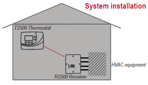
Getting started
- This booklet provides an installation guide, wireless pairing instructions, and advanced configuration options for the R2500 and T2500. Please note:
- In order to establish correct pairing, the R2500 must be mounted and wired before applying power to the T2500.
- Read and understand the “Advanced Configuration” section to determine your preferred settings on the T2500 before performing wireless pairing
WavePRO Wireless System pre-installation checklist
- WavePRO Wireless System (T2500 and R2500) mounting considerations:
- Locate the T2500 and R2500 within 100 ft. (30 m.) of one another.
- Avoid locating devices within a metal enclosure or between large obstructions.
- The WavePRO Wireless System will communicate through walls and other obstructions, but these may reduce the effectiveness of its operating range
Required tools & supplies:
- No. 2 Phillips screwdriver
- Small flathead screwdriver
- Drill
- Drill bit (3/16” for drywall, 7/32 for plaster) Hammer
- Pencil
- Electrical tape
- Level (optional)
- Two new AA batteries
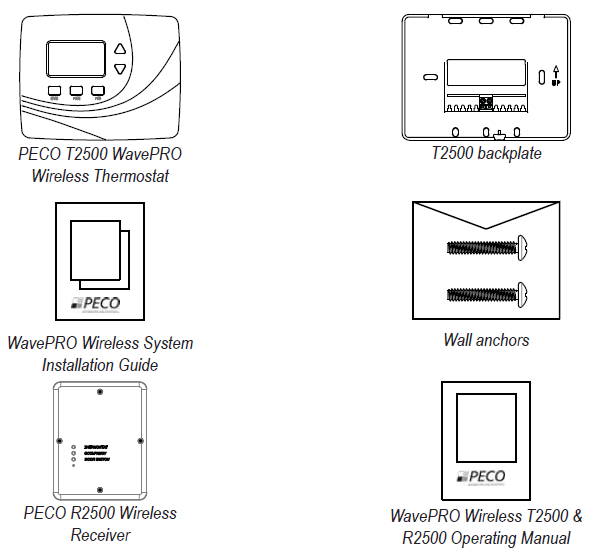
Install R2500 Receiver
The following section provides installation instructions for the R2500 wireless receiver.
Note: In order to establish correct pairing, the R2500 must be mounted and wired before applying power to the T2500.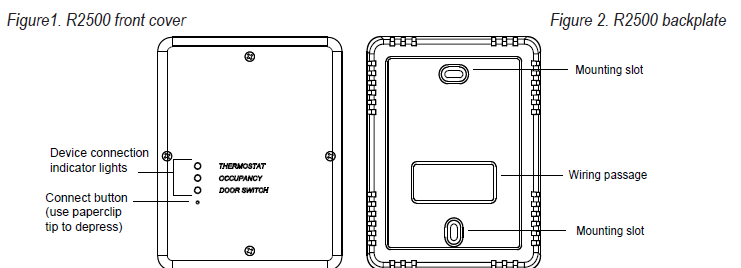
INSTALLATION TIPS
WARNING:
- Disconnect power before beginning installation.
- Mount the R2500 on a wall near the HVAC equipment.
- Choose indoor mounting locations free from obstructions.
- Use copper wire only. Insulate or wire-nut all unused leads.
- Use care to avoid electrostatic discharge to thermostat and receiver.

R2500 wiring and mounting instructions
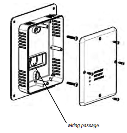
- Remove the R2500 front cover (see Fig. 3) by loosening screws.
- Pull equipment wires through the R2500 wiring passage (see Fig. 4).
- Drill holes appropriately in the mounting surface.
- Mount the R2500 using the enclosed mounting screws. Tighten screws evenly.
- Connect equipment wire to the R2500 terminals:
- Match equipment wire to the R2500 terminals, referencing the appropriate wiring examples below (see “R2500 wiring examples” section of these instructions for assistance with single-stage, multi-stage, heat pump, and traditional applications).
- Loosen screw terminals.
- Insert wires into the appropriate terminals.
- Re-tighten screw terminals.
- Cap off unused wires or terminate properly according to local building codes.
- Re-attach the R2500 front cover (see Fig. 4).
R2500 wiring examples
The following are examples of typical wiring confi gurations for the R2500 (see Fig. 5 and Terminal Designations Overview below). Please contact a service technician if you are unable to perform the wiring installation
Terminal Descriptions
| Conventional Terminal Letters Heat Pump Terminal Letters | |||
| C | Common wire from secondary side of system transformer. | C | Common wire from secondary side of system transformer. |
| R | Power connected to system transformer. | R | Power connected to system transformer. |
| W | First stage of heat relay/contactor. | Y | First stage of compressor contactor. |
| W2 | Second stage of heat relay/contactor. | Y2 | Second stage of compressor contactor. |
| Y | First stage cool relay/contactor. | Aux | Auxiliary heat relay/contactor. |
| Y2 | Second stage cool relay/contactor. | G | Fan relay. |
| G | Fan relay. | E | Emergency heat relay/contactor. |
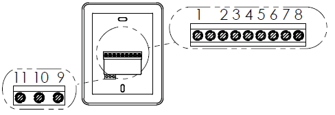
Terminal Designations Overview
| Terminal | Heat Pump Systems | Conventional Systems | ||
| 1 | C | 24VAC 2 | C | 24VAC 2 |
| 2 | R | 24VAC 1 | R | 24VAC 1 |
| 3 | Y1 | COMP 1 | Y1 | COOL 1 |
| 4 | Y2 | COMP 2 | Y2 | COOL 2 |
| 5 | O/B | REV. VALVE | W1 | HEAT 1 |
| 6 | AU | AUX HEAT | W2 | HEAT 2 |
| 7 | A | ECON | A | ECON |
| 8 | G | FAN | G | FAN |
| 9 | Remote probe common | |||
| 10 | Unused | |||
| 11 | Remote probe | |||
R2500 wiring examples
| System Type 0 (1H/1C CONV) | ||
| TERM | Name | Function |
| 1 | C | 24VAC 2 |
| 2 | R | 24VAC 1 |
| 3 | Y1 | Cooling |
| 4 | Y2 | |
| 5 | W1 | Heating |
| 6 | W2 | |
| 7 | A | Economizer |
| 8 | G | Fan |
| System Type 1 (1H/1C HP) | ||
| TERM | Name | Function |
| 1 | C | 24VAC 2 |
| 2 | R | 24VAC 1 |
| 3 | Y1 | Compressor 1 |
| 4 | Y2 | |
| 5 | O/B | Reversing valve |
| 6 | AU | |
| 7 | A | Economizer |
| 8 | G | Fan |
| System Type 2 (1H/1C HP + Emergency) | ||
| TERM | Name | Function |
| 1 | C | 24VAC 2 |
| 2 | R | 24VAC 1 |
| 3 | Y1 | Compressor 1 |
| 4 | Y2 | |
| 5 | O/B | Reversing valve |
| 6 | AU | Emergency |
| 7 | A | Economizer |
| 8 | G | Fan |
| System Type 3 (1 Heat without Fan) | ||
| TERM | Name | Function |
| 1 | C | 24VAC 2 |
| 2 | R | 24VAC 1 |
| 3 | Y1 | |
| 4 | Y2 | |
| 5 | W1 | Heating |
| 6 | W2 | |
| 7 | A | Economizer |
| 8 | G | |
| System Type 4 (1 Heat with Fan) | ||
| TERM | Name | Function |
| 1 | C | 24VAC 2 |
| 2 | R | 24VAC 1 |
| 3 | Y1 | |
| 4 | Y2 | |
| 5 | W1 | Heating |
| 6 | W2 | |
| 7 | A | Economizer |
| 8 | G | Fan |
| System Type 5 (Cooling Only) | ||
| TERM | Name | Function |
| 1 | C | 24VAC 2 |
| 2 | R | 24VAC 1 |
| 3 | Y1 | Cooling |
| 4 | Y2 | |
| 5 | W1 | |
| 6 | W2 | |
| 7 | A | Economizer |
| 8 | G | Fan |
| System Type 6 (2H/1C HP) | ||
| TERM | Name | Function |
| 1 | C | 24VAC 2 |
| 2 | R | 24VAC 1 |
| 3 | Y1 | Compressor 1 |
| 4 | Y2 | |
| 5 | O/B | Reversing valve |
| 6 | AU | Aux heat/Emergency |
| 7 | A | Economizer |
| 8 | G | Fan |
| System Type 7 (2H/2C Conventional) | ||
| TERM | Name | Function |
| 1 | C | 24VAC 2 |
| 2 | R | 24VAC 1 |
| 3 | Y1 | Cooling stage 1 |
| 4 | Y2 | Cooling stage 2 |
| 5 | W1 | Heating stage 1 |
| 6 | W2 | Heating stage 2 |
| 7 | A | Economizer |
| 8 | G | Fan |
| System Type 8 (2H/1C Conventional) | ||
| TERM | Name | Function |
| 1 | C | 24VAC 2 |
| 2 | R | 24VAC 1 |
| 3 | Y1 | Cooling stage 1 |
| 4 | Y2 | |
| 5 | W1 | Heating stage 1 |
| 6 | W2 | Heating stage 2 |
| 7 | A | Economizer |
| 8 | G | Fan |
| System Type 9 (1H/2C Conventional) | ||
| TERM | Name | Function |
| 1 | C | 24VAC 2 |
| 2 | R | 24VAC 1 |
| 3 | Y1 | Cooling stage 1 |
| 4 | Y2 | Cooling stage 2 |
| 5 | W1 | Heating stage 1 |
| 6 | W2 | |
| 7 | A | Economizer |
| 8 | G | Fan |
| System Type 10 (2H/2C HP) | ||
| TERM | Name | Function |
| 1 | C | 24VAC 2 |
| 2 | R | 24VAC 1 |
| 3 | Y1 | Compressor 1 |
| 4 | Y2 | Compressor 2 |
| 5 | O/B | Reversing valve |
| 6 | AU | |
| 7 | A | Economizer |
| 8 | G | Fan |
| System Type 11 (3H/2C HP) | ||
| TERM | Name | Function |
| 1 | C | 24VAC 2 |
| 2 | R | 24VAC 1 |
| 3 | Y1 | Compressor 1 |
| 4 | Y2 | Compressor 2 |
| 5 | O/B | Reversing valve |
| 6 | AU | Aux heat/Emergency |
| 7 | A | Economizer |
| 8 | G | Fan |
Install the T2500 Thermostat backplate
The T2500 Thermostat is intended for indoor installation only. It should be mounted on an inner wall, in a location with freely circulating air, where it will be responsive to changes in room temperature. Avoid mounting the thermostat near heat-generating appliances (i.e., TV, heater, refrigerator), or in direct sunlight. This instruction assumes that the installer will use pre-existing wires found at the location of the previously-installed thermostat
Power Options The T2500 will operate on 24 VAC power and/or two AA alkaline batteries. Where possible, the thermostat should be operated on 24 VAC power with battery backup.
Remove the old thermostat
- Turn off all power for heating/cooling system (or for fuse/circuit breaker panel) before installing thermostat to avoid electrical shock or damage to equipment.
- Remove the cover of old thermostat (see Fig.6).
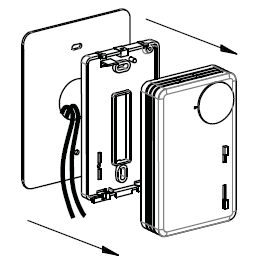
- Label each wire with the terminal to which it was attached before removing wires from the old thermostat (see Fig.7).
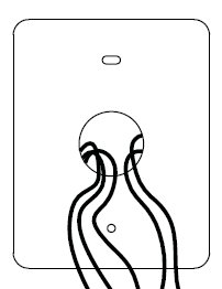
- Disconnect wires. Do not let wires fall back into the wall.
- Remove backplate from the wall after all wires are labeled. If old thermostat has a wall mounting plate, remove both of these as an assembly
- Use a level to mark the backplate mounting position.
- Mark positions of the screw holes (two at minimum) with a pencil.
- Drill holes at pencil-marked locations (3/16” for drywall, 7/32” for plaster).
- Insert the wall anchors in the holes. Use a hammer to gently tap anchors into holes.
- Mount the T2500 Thermostat backplate on the wall. Assure that all loose wires come through the center opening of the backplate (see Fig. 8).
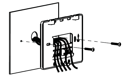
Attach wires to the T2500 Thermostat backplate
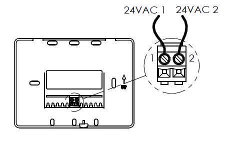
- Using a small flathead screwdriver, loosen the screws on the terminal block, located on the backplate, to allow the wires to be inserted easily.
- Strip the insulation of each wire at a proper length (about 1/4” or .64cm).
- Insert the appropriate wires into the terminal block as shown in the wiring diagram below (see Fig. 9 ).
- Connect 24VAC 1 to terminal 1
- Connect 24VAC 2 to terminal 2
- Tighten each terminal block screw until the wires are held firmly in place. Ensure that no uninsulated wire is exposed.
Install batteries in the T2500
Batteries are recommended for the T2500 Thermostat. Insert two AA batteries (included) in the T2500 Thermostat back compartment where indicated (see Fig. 10). Assure batteries are inserted properly
Perform advanced configuration of the T2500 before pairing.
Perform advanced configuration for thermostat before performing wireless pairing. (See “Advanced Configuration” section). Advanced configuration allows you to customize thermostat settings, such as temperature display, time and day display, programming commands, and to create setpoints for scheduling different time periods. For more information on using the thermostat’s buttons and features, refer to the “WavePRO Wireless Programmable T2500 Thermostat & R2500 Receiver Operating Manual.”
Establish a wireless connection
Perform wireless pairing after the R2500 is installed and the advanced configuration is complete. For best results, perform wireless pairing before the T2500 Thermostat is attached to the backplate
- Turn on power to both the T2500 and R2500. Note: DO NOT attempt to pair more than one WavePRO Wireless System simultaneously.
- Using a paperclip on the R2500 Receiver, push and hold the CONNECT button until all three LED lights flash for about 10 seconds (see Fig.11).
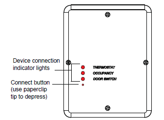
- If only two LEDs flash, continue pressing CONNECT button until all three LEDs flash.
- Push simultaneously ▲ and ▼ buttons on T2500 until 1 appears in Display.
- Push the SYSTEM button continuously until Service Menu 43 appears.
- Pause at Service Menu 43. The display will change to 0.
- Push ▲ the button to change the 0 to 1 within Service Menu Function 43.
- T2500 Display will begin the countdown from 99 and stop before 0. (Countdown indicates that the pairing process has begun).
- Wait for the Service Indicator
 on the T2500 to begin flashing (indicating the R2500 was found but pairing process is not yet complete).
 - T2500 Display will show the room temperature.
- Wait for up to 10 minutes to allow completion of pairing process.
- Do not press buttons during this process. Wireless pairing is successful only when you see the following:
- R2500 “Thermostat” LED is continuously lit.
- T2500 Service Indicator disappears from Display
Verify wireless pairing
- Press the FAN button on T2500 Thermostat.
- Press the FAN button continuously until ON is flashing.
- Allow timeout. The flashing menu option (ON) is automatically selected.
- Note: The fan blower should begin to operate (there may be a delay).
- Press the FAN button until AUTO begins flashing so it is automatically selected.
- Note: FAN has now been reset to AUTO.
- Allow the device to time out. Wireless verification is complete
Interpreting the R2500 Indicator LEDs
LED indicator lights on the R2500 may also be used to diagnose communication errors. Use the following table to interpret the R2500 LEDs.
If R2500 LED… Interpretation
- Blinks once R2500 is receiving valid messages from another device.
- Blinks twice R2500 is receiving invalid messages from another device
- Blinks intermittently R2500 is receiving invalid messages that may be caused by an excessive amount of obstruction between the R2500 and other wireless paired devices; or from excessive interference from other wireless devices. Note: If the R2500 LEDs indicate invalid messages frequently, review for help the following sections: “Install R2500 Receiver” or “Frequently asked questions & troubleshooting.”
If replacing either the T2500 or the R2500, follow these instructions:
A brief connection process must be performed that erases all previously paired devices from the R2500 memory. Hold the CONNECT button down until all the LED lights begin to flash (about 10 seconds). Wait until all three LEDs stay lit for one (1) second and begin to flash. Begin the pairing process again at section “5. Establish a wireless connection
Mount the T2500 onto the backplate
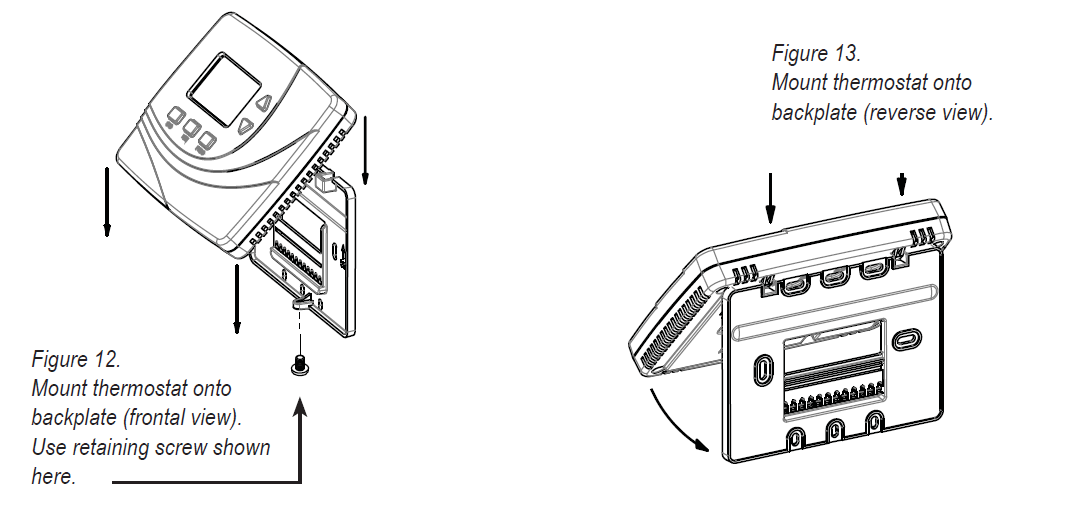
- Attach the thermostat by sliding the mounting tabs (on its reverse side) down onto the hinge pockets on the backplate (see Fig. 12-13). Make sure that thermostat’s pins on reverse fit securely into the terminal block on the backplate.
- Install retaining screw provided with the mounting hardware (see Fig. 12).
- Note: Inserting the retaining screw is recommended to assure thermostat is securely attached to the wall
Advanced configuration: T2500 Thermostat
In the following section, you will learn how to access SYSTEM (SYS) menu options for advanced confi guration. To access the system menu, follow the instructions below. After you access each service menu option, a default value will appear on the screen.
- Simultaneously press ▲ and ▼ buttons until you see “1” in the Display.
- Press SYS button continuously to scroll until desired menu number appears.
- Press ▲ and ▼to select desired option once you enter the service menu
Temperature Display °F / °C: Select Fahrenheit (°F) or Celsius (°C)
- Menu 1 0=°C; 1=°F
- Default: 1 (Fahrenheit) Options: 0, 1 Selection:_________
Fan Delay: Select the fan on time after demand has ended
- Menu 3
- Default: 0 Options: 0 to 99 seconds Selection:_________
Temperature Range Low: Select the lowest user-selectable temperature value
- Menu 4
- Default: 50°F Options: 50-90 °F / 10-32 °C Selection:_________
Temperature Range High: Select the highest user-selectable temperature value
- Menu 5
- Default: 90°F Options: 50-90 °F / 10-32 °C Selection:_________
Setback Low: Select HEAT temperature value when in the Setback mode (0 is OFF)
- Menu 6 0= OFF
- Default: 55°F Options: 50-82 °F / 10-28 °C Selection:_________
Setback High: Select COOL temperature value when in the Setback mode (0 is OFF)
- Menu 7 0= OFF
- Default: 90°F Options: 58-90 °F / 10-28 °C Selection:_________
Zone Temperature Offset: Select temperature display value; value may differ from actual zone temperature
- Menu 8
- Default: 0°F Options: +/- 9°F, +/- 4.5°C Selection:_________
Advanced configuration
Keypad Lockout: Select to allow restrictions to occupant access
- Menu 9 0= No keypad lockout
- 1= Disables all buttons except ▲ and ▼ buttons.
- 2= Disables all buttons
- Default: 0 Options: 0-2 Selection:_________
Fan Program Mode: Select desired option
- Menu 10 1= ON: Fan is always on regardless of demand
- 2= AUTO: Fan is only on with heating or cooling demand
- 3= ON or AUTO: User can choose either selection
- Default: 3 Options: 1-3 Selection:_________
System Program Mode: Select to determine which system modes occupant can select
- Menu 12 0= OFF, AUTO
- 1= OFF, HEAT, COOL, AUTO
- 2= OFF, HEAT, COOL
- 3= AUTO, HEAT, COOL
- Default: 1 Options: 0-3 Selection:_________
Front Panel Setback Mode Enable: Allows user to select “setback” as a system mode
- Menu 14 0= Disable
- 1= Enable
- Default: 0 Options: 0-1 Selection:_________
Deadband Adjust: Select the changeover deadband value to prevent short cycling between heating and cooling modes; adjustable to meet HVAC system requirements
- Menu 17
- Default: 3 °F Options: 3-10 °F / 1.5-5 °C Selection:_________
Pre-occupancy Purge: Select period of time fan will run prior to Wake and Day periods
- Menu 25 Pre
- Default: 0 Options: 0 to 3 hours Selection:_________
Cycles Per Hour (CPH) for Cool Stage 1: Select Cycles Per Hour for Cool Stage 1; 0 disables cycling and thermostat becomes an ON/OFF control
- Menu 30
- Default: 3 CPH Options: 0 to 6 CPH Selection:_________
Cycles Per Hour (CPH) for Heat Stage 1: Select Cycles Per Hour for Heat Stage 1; 0 disables cycling and thermostat becomes an ON/OFF control
- Menu 32
- Default: 5 CPH Options: 0 to 12 CPH Selection:_________
Recovery Rate for Heat: Set temperature for heat recovery rate; 0 disables ramp recovery, uses step response
- Menu 35
- Default: 5°F/Hr, 3°C/Hr Options: 0-18°F/Hr, 0-10°C/Hr Selection:_________
Recovery Rate for Cool: Set temperature for cool recovery rate; 0 disables ramp recovery, uses step response
- Menu 36
- Default: 5°F/Hr, 3°C/Hr Options: 0-18°F/Hr, 0-10°C/Hr Selection:_________
Output Minimum Off Time for Heat and Cool: Set the minimum “off time” for heat and cool output
- Menu 40
- Default: 4 min. Options: 1-10 minutes Selection:_________
Temp Source: Allows use of remote sensor option on R2500
- Menu 42 0= Temperature will be measured by T2500 internal sensor
- 1= Temperature will be measured by R2500 remote sensor
- Default: 0 Options 0,1 Selection:_________
Pairing Start: Allows pairing of T2500 Thermostat with the R2500 Receiver
- Menu 43 0= OFF: Not pairing: Thermostat will not pair with the R2500 Receiver
- 1= ON: Pairing: Thermostat will attempt to pair with the
- R2500 Receiver
- Default: 0 Options 0,1 Selection:_________
Intermittent Fan Enable: If enabled, intermittent fan will cycle when there is no demand
- Menu 45 0= Disable
- 1= Enable
- Default: 0 Options 0, 1 Selection:_________
Intermittent Fan On Time: Minutes the fan will be on when the intermittent fan is enabled
- Menu 46
- Default: 5 min. Options: 1-60 min. Selection:_________
FAQS
- In case of difficulty, try one of the following suggestions.
- If the Display is blank Assure two fresh AA alkaline batteries are installed (see p. Install batteries on the T2500”)
- If you cannot establish a wireless connection for the
- T2500 Thermostat and R2500 Receiver
- Assure distance between T2500 Thermostat and R2500
- The receiver during setup is about 6-10 feet (3 m.)(see p. 11, “5. Establish a wireless connection”).
- Monitor the T2500 Thermostat display during the pairing process.
- If pairing is successful, Display will change to show the current temperature before the countdown reaches 0.
- R2500 Receiver will attempt to connect to any available device for up to two (2) minutes.
- Do not attempt to pair more than one set of wireless devices.
- If T2500 Display counts down to 0, the wireless pairing was unsuccessful
- Restart the wireless pairing process (see p.11, “5. Establish a wireless connection”).
- If the “Thermostat” LED on
- 2500 Receiver is “flashing”
- Wait until the Thermostat LED on R2500 is continuously lit, indicating the connection is established (see p. 4, “1. Install R2500 Receiver.” and p. 12, “5. Establish a wireless connection”).
- If the connection is broken between R2500 and T2500 for more than 10 minutes
- “Thermostat” LED light will shut off on the R2500 and will shut off all outputs
- Verify that both R2500 and T2500 have power.
- If the Thermostat LED light on the R2500 does not appear, bring the T2500 and R2500 within about 6-10 feet (3 m.).
- The thermostat LED on the R2500 should appear. If no
- The thermostat LED appears, contact a service technician.
- If Service Indicator continues flashing
- Assure that you have waited at least 10 minutes for wireless pairing to occur between T2500 Thermostat and R2500
- Receiver (a process generally takes 3-10 minutes).
- Restart the wireless pairing process (see p.11, “5. Establish a wireless connection”).
- If the heating or cooling system does not respond
- Increase setpoint to greater than deadband value (see
- Service menu 17 in “Advanced confi guration.”)
- Decrease setpoint to less than deadband value (see Service menu 17 in “Advanced configuration.”)
- Check the circuit breaker and reset if necessary.
- Assure the power is on for the heating and cooling system is on.
- Assure the furnace door is closed securely.
- Wait at least fi ve minutes for the system to respond.
- Use Menus 80-83, “Advanced configuration” to verify system wiring.
- If heating and cooling equipment running at the same time (or the heat does not turn off)
- Check SYS menu 50 to assure that it is set to match your heating and cooling equipment.
- Turn off the power to R2500 Receiver. Remove the cover and verify the wiring.
Product specifications
- Temperature Range 50° to 90° F (10° to 32° C)
- Differential 1° F (0.5°C)
- Input Power T2500 Thermostat: Two AA alkaline batteries or 24 VAC, 50/60 Hz
- R2500 Receiver: 24 VAC, 50/60 Hz
- Output Power 24 VA (Pilot Duty)
- Wireless Type 902 to 928 MHz Band, Frequency Hopping Spread Spectrum (FHSS)
- Wireless Range 100 feet (30.48 meters) typical reliable range in open air
- Operation Temperature 0° to 120° F (-17° to 48°C)
- Shipping Temperature -20° to 130°F (-28°to 54°C)
- Operating Humidity 5% to 95% RH, non-condensing
- Physical dimensions T2500: 4.5”H x 5.75” W x 1.1”; D R2500: 4.8”H x 3.8”W x 1.3”D
FCC
This device complies with part 15 of the FCC rules. Operation is subject to the following two conditions:
- this device may not cause harmful interference, and
- this device must accept any interference received, including interference that may cause undesired operation.
Warning: Modifications not expressly approved by the manufacturer could void the user’s authority to operate the equipment under FCC rules. NOTE: This equipment has been tested and found to comply with the limits for a Class A digital device, pursuant to part 15 of the FCC Rules. These limits are designed to provide reasonable protection against harmful interference in a residential installation. This equipment generates, uses and can radiate radio frequency energy and, if not installed and used in accordance with the instructions, may cause harmful interference to radio communications. However, there is no guarantee that interference will not occur in a particular installation. If this equipment does cause harmful interference to radio or television reception, which can be determined by turning the equipment off and on, the user is encouraged to try to correct the interference by one or more of the following measures:
- Reorient or relocate the receiving antenna.
- Increase the separation between the equipment and the receiver.
- Connect the equipment to an outlet on a circuit different from that to which the receiver is connected.
- Consult the dealer or an experienced radio/TV technician for help.
REFERENCE
DOWNLOAD MANUAL
Peco T2500 Wireless Programable Thermostat Installation Guide
OTHER MANUALS:
Peco T2500 Wireless Programable Thermostat Operational Manual

Peco T2500 Wireless Programable Thermostat Installation Guide