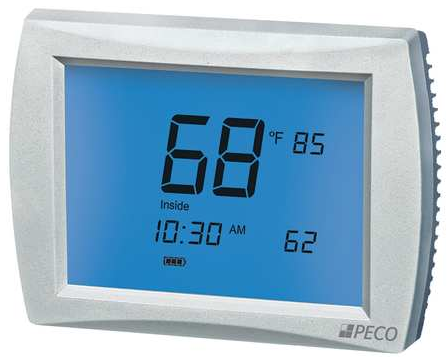
PECO T190 Programmable THERMOSTAT
WARNING
- READ THESE INSTRUCTIONS CAREFULLY BEFORE ATTEMPTING TO INSTALL, OPERATE OR SERVICE THIS THERMOSTAT.
- Failure to observe safety information and comply with instructions could result in PERSONAL INJURY, DEATH, AND/OR PROPERTY DAMAGE.
- To avoid electrical shock or damage to equipment, disconnect the power before installing or servicing and use only wiring with insulation rated for full thermostat operating voltage.
- Before installing this control, the Voltage Selection Switch must be placed in the correct position. See instructions.
- To avoid potential fire and/or explosion do not use in potentially flammable or explosive atmospheres.
- Retain these instructions for future reference. This product, when installed, will be part of an engineered system whose specifications and performance characteristics are not designed or controlled by
PECO. You must review your application and national and local codes to assure that your installation will be functional and safe.
APPLICATIONS AND FEATURES
The T190 thermostat is a low-voltage programmable thermostat designed to control most conventional systems. It is configurable for up to two-stage heat and two-stage cool and has manual or auto-changeover modes. The thermostat is 7-day programmable, with different heating and cooling setpoints for 4 time periods per day. The thermostat can also, be set to nonprogrammable (manual) operation.
System Types (up to 2 Heat / 2 Cool)
- Gas, oil, or electric heat with air conditioning
- Heat pumps
- Heat-only, two-wire systems
- Heat only with a fan
- Cool only
Do not use systems with more than 2-stage heat and 2-stage cool, systems exceeding 30 VAC and 1 amp, millivolt systems, or hydronic systems. Power Options The thermostat will operate on either 24 VAC power or two AA alkaline batteries. The thermostat does not need batteries to
Power Options
The thermostat will operate on either 24 VAC power or two AA alkaline batteries. The thermostat does not need batteries to store user-configured settings in memory. During power loss, nonvolatile memory saves all user settings, configurations, and usage counters for an unlimited time.
Specifications
- Temperature Setpoint Range: 50° to 90°F (10° to 32°C)
- Differential: 1°F
- Voltage & Frequency: 24 VAC, 50/60 Hz
- Battery: 2.6 – 3.1 VDC
- (two AA alkaline batteries)
- Operating Ambient Temperature: 32° to 122°F (0° to 50°C)
- Shipping Temperature: 23° to 140°F (-5° to 60°C)
- Operating Relative Humidity: 5% to 95% RH, non-condensing
Physical Dimensions: 3.6” H x 5.3” W x 1.4” D
Mounting Location
The thermostat should be used indoors only. It should be mounted on an inner wall 48” from the floor, in a location with freely circulating air and where it will respond to changes in room temperature. Avoid mounting near heat-generating appliances (e.g. computer, heater, refrigerator), or in direct sunlight.
PACKAGE CONTENTS
Your package includes the following items:
- T190 programmable thermostat
- Installation Instructions
- Owner’s Manual
- Wall anchors and mounting screws (2 each)
- AA alkaline batteries (2)
INSTALLATION
WIRING AND MOUNTING
- To avoid electrical shock or damage to equipment, disconnect the power before installing this thermostat.
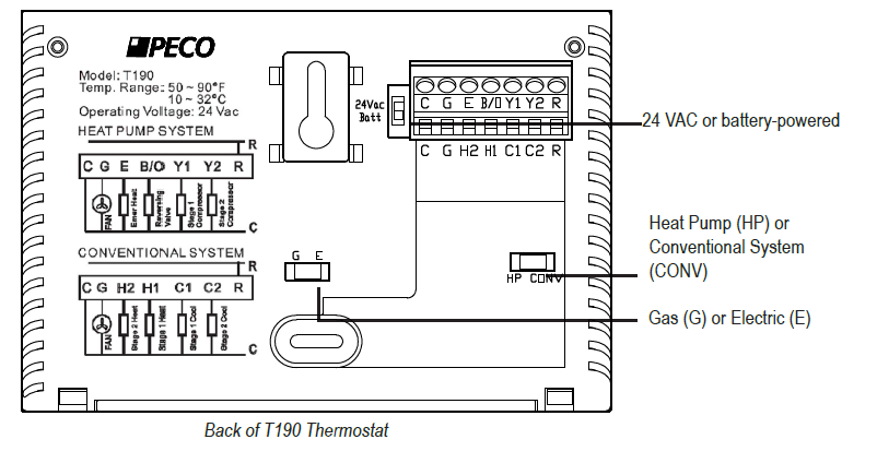
- Position the three switches on the back of the thermostat, according to the HVAC system being controlled and the power source.
- Connect electrical:
- If using a mounting plate: Pull the wires out of the middle hold of the mounting plate and adjust the plate on the wall or junction box.
- Loosen screw terminals, and insert wires into the appropriate terminals, then re-tighten the screws.
- Cap off all unused wires. All connections must be located in the outlet box. Conventional System Terminal Designations
| Terminal | Input/ Output | Description |
| C | Input | Unswitched Side, 24 VAC |
| G | Output | Fan |
| H2 | Output | Stage 2 Heat |
| H1 | Output | Stage 1 Heat |
| C1 | Output | Stage 1 Cool |
| C2 | Output | Stage 2 Cool |
| R | Input | Switched Side, 24 VAC |
Heat Pump System Terminal Designations
| Terminal | Input/ Output | Description |
| C | Input | Unswitched Side, 24 VAC |
| G | Output | Fan |
| E | Output | Auxillary or Emergency Heat |
| B/O | Output | Reversing Valve |
| Y1 | Output | Compressor Stage 1, Heat 1 or Cool 1 |
| Y2 | Output | Compressor Stage 2, Heat 2 or Cool 2 |
| R | Input | Switched Side, 24 VAC |
The thermostat mounts to a horizontal or vertical 2×4 junction box with the use of an accessory mounting plate or may be mounted directly to the wall:
- Place the 2 wall anchors into the wall.
- Fasten the thermostat with the screws provided through the 2 mounting holes. One mounting hole is accessible through the battery compartment (located under the front cover of
thermostat). - Place two AA alkaline batteries into the battery compartment (located under the front cover of the thermostat).
Note: In these instructions, the term “Normal Mode” refers to the default thermostat display (i.e. when the user is not performing any operations). The default display shows the current time, current room temperature, day of the week, event, system mode, and program selection. Pressing the button always takes the thermostat to Normal Mode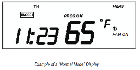
The installer must configure the thermostat to match the installed heating/cooling system. The Service Menu allows the installer to modify configuration variables that are not normally accessed by the end user. The configuration variables are identified by Menu Number, as listed in the “Service Menu
Functions” table.
Accessing the Service Menu
From the Normal Mode thermostat display, simultaneously Press the ▲ and ▼ buttons, and hold down for 5 seconds. This takes you to the Service Menu and menu item number
- will be flashing.
- Push PROG to scroll to the Service Menu item number to be configured.
- Push ▲ ▼ buttons to configure the selected menu item. The service menu number is always shown in the small digits; selection values are shown in the larger digits or other icons as appropriate
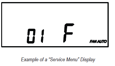
- To save your configuration selection and go to the next Menu Number, press PROG. Saving and Exiting the Service Menu The Service Menu exits and returns to Normal Mode after 60 seconds of inactivity or by pressing the button. Changed values are saved to permanent memory.
CHECK THERMOSTAT OPERATION
After wiring and configuration are complete, turn on the power at the main fuse or circuit breaker box. Check thermostat operation:
- Set the fan to ON. The blower should begin to operate.
- Set the System Switch to AUTO, or available selection.
- Using the ▲ button, adjust the temperature above the room temperature to cycle the heating stage(s) on. Using the ▼ button, adjust the temperature below the room temperature to cycle the cooling stage(s) on. Refer to Owner’s Manual for instructions on how to operate and program the thermostat.
Note: All menu numbers may not appear, depending upon the T190 model.
| MENU | FEATURE | RANgE | STD. MODEL DEFAULT | DESCRIPTION / COMMENTS |
| 1 | F / C Display | °F or °C | °F | Sets the temperature display in Fahrenheit (F) or Celsius (C). |
| 4 | Range Limit Low | 50-90°F,
10-32°C |
50°F | Sets the lowest value the user can select for the setpoint. |
| 5 | Range Limit High | 50-90°F,
10-32°C |
90°F | Sets the highest value the user can select for the setpoint. |
| 8 | Zone Temp Offset | +/- 9°F,
+/- 4.5°C |
0°F | Zone Temperature offset adjusts the sensed Zone Temperature reading from the A to
D converter, allowing calibration in the field. |
| 9 | Keypad Lock | 0-3 | 0= OFF | Allows you to choose what the occupant can access. The Service Menu is still available if Key Pad Lock Out is ON.
0= OFF= No keypad lockout. 1= ON1= Disables all functions except the System key, Temporary Override and Permanent Override. 2= ON2= Disables all functions except Temporary Override and Permanent Override. 3= ON3= Disables all functions. |
| 17 | Minimum Deadband Adjust | 3-9°F,
1.5-5°C |
3°F | Sets the minimum difference between the Cool and Heat Setpoints (Deadband). Heat and Cool setpoints are to be adjusted as equally as possible to meet the Minimum Deadband and Range Limits. The Minimum Deadband must not exceed the (Range Limit High – Range Limit Low). |
| 18 | Factory Default Reset | 0-1 | 0= OFF | 0= OFF= No reset.
1= DFLT= Resets to Factory Default; retains only clock settings. |
| 20 | Reversing Valve Type | 0-1 | 0= O | 0= O= Energize on Cool or Deadband (not heat) 1= B= Energize on Heat or Deadband (not cool) |
| 21 | System Type | 0-1 | 0= CV | 0= CV= Conventional System Logic 1= HP= Heat Pump Logic |
| 22 | Heat Stages | 1-2 | 2 | |
| 23 | Cool Stages | 1-2 | 2 | |
| 30 | Cycles Per Hour (CPH) for First Stage Compressor | 0-6 CPH | 3 CPH | Applies to Heat Pump or Conventional Cooling, 0 disables cycling |
| 31 | Cycles Per Hour (CPH) for Second Stage Compressor | 0-6 CPH | 3 CPH | Applies to Heat Pump or Conventional Cooling, 0 disables cycling |
| 32 | Cycles Per Hour (CPH) for First Stage Heat | 0-12 CPH | 5 CPH | Applies to Conventional Heating only, 0 disables cycling |
| 33 | Cycles Per Hour (CPH) for Second Stage Heat | 0-12 CPH | 5 CPH | Applies to Conventional Heating, and second stage of heat in 2H1C Heat Pump (Y2 output) only, 0 disables cycling |
| 34 | Cycles Per Hour (CPH) for
Emergency Heat |
Applies to Heat Pumps only, 0 disables cycling | ||
| 35 | Heat Recovery Rate | 0-18°F/Hr
0-10°C/Hr |
5°F/Hr
3°C/Hr |
0 disables ramp recovery, uses step response |
| 36 | Cool Recovery Rate | 0-18°F/Hr
0-10°C/Hr |
5°F/Hr
3°C/Hr |
0 disables ramp recovery, uses step response |
COPYRIGHT 2009 PECO, INC. TOUS DROITS RÉSERVÉS. Réf. 69535 3220-2151 RÉV. 0 PAGE 12
Reference:
Download Manual:
PECO T190 Programmable THERMOSTAT Installational Instruction

PECO T190 Programmable THERMOSTAT Installational Instruction