PECO T168 Proportional THERMOSTAT
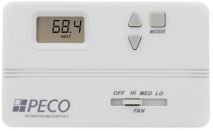
INSTALLATION
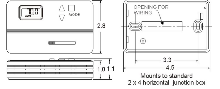
- Install the T168 with the two furnished mounting screws to a standard 4 1/16” x 2 1/8” square device box with a 2” x 4” adapter ring.
- For wall installations, mount the thermostat on an inside wall approximately 5 feet above the floor. The locations should provide circulation at an average room temperature. Avoid direct sunlight or sources of hot or cold air in the room.
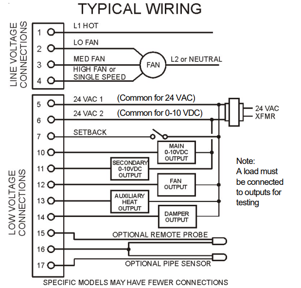
- Remove the cover. Mount the thermostat base assembly to the outlet box using the screws provided. Tighten the screws evenly but do not overtighten. Connect wires per the wiring diagram.
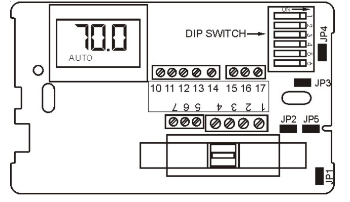
- To use a remote sensor on units with local sensing capability, remove jumper JP-1 to disable local sensing. Failure to remove JP-1 will cause improper operation of the thermostat.
- Connecting a jumper between terminals 16 and 17 will disable the secondary output and change the main output to heat mode.
- The connection of a 24 VAC setback signal will force the control into an unoccupied mode (see diagram). Pressing an arrow key or the mode buttons on the thermostat cover will disable the setback input for one hour.
- Remove the LCD plastic protective film to complete the installation. Reinstall the cover assembly. Install the cover locking screw provided.
- Checkout: After wiring and installation are complete, energize the system and check the operation. Adjust the thermostat as necessary to complete at least one cycle. Be sure the thermostat and all other equipment are functioning correctly.
CAUTION
- Use Copper wire only, insulate or wire nut all unused leads.
- Care should be used to avoid electrostatic discharge to the microprocessor.
- This unit has configuration dip switches and jumpers. You may need to reconfigure the thermostat for your application.
MOUNTING
WARNING
- READ THESE INSTRUCTIONS CAREFULLY BEFORE ATTEMPTING TO INSTALL, OPERATE OR SERVICE THIS THERMOSTAT.
- Failure to observe safety information and comply with instructions could result in PERSONAL INJURY, DEATH, AND/OR PROPERTY DAMAGE.
- To avoid electrical shock or damage to equipment, disconnect the power before installing or servicing.
- To avoid electric shock or damage to equipment, use only wiring with insulation rated for full thermostat operating voltage.
- To avoid potential fire and/ or explosion do not use it in potentially flammable or explosive atmospheres.
- Retain these instructions for future reference. This product, when installed, will be part of an engineered system whose specifications and performance characteristics are not designed or controlled by PECO, Inc. You must review your application and national and local codes to assure that your installation will be functional and safe.
WIRING DIAGRAM
ELECTRICAL RATING
| ELECTRICAL RATINGS | |||||
| Fan Switch (Terminals 1-4) Line Voltage Connections | |||||
| Voltage | Inductive |
Resistive |
Pilot |
Thermostatic Switching/ Low Voltage | |
| FLA | LRA | ||||
| 24 VAC | N.A. | N.A. | N.A. | 24 VA | 10 VA |
| 120 | 5.8 | 34.8 | 6.0 | 125 VA | N.A. |
| 240 | 2.9 | 17.4 | 5.0 | 125 VA | N.A. |
| 277 | 2.4 | 14.4 | 4.2 | 125 VA | N.A. |
APPLICATION NOTES
- When no changeover pipe sensor is used, the main output controls cooling and the secondary output controls heating.
- The fan output, terminal 12, is energized whenever there is a demand for heating or cooling. This output can be connected to a relay that can be used to provide fan cycling to terminal 1.
- The changeover pipe sensor should be mounted on the main coil input for water system operation and in the main duct system for forced air operation.
- The set point and operating mode will be retained on a loss of power.
- When using either a remote probe or pipe sensor, run the wiring away from any electrical motors or power wiring.
- The auxiliary heat output supplies a 24 VAC signal with a call for heat. This output is shipped configured for staged heat.
- The thermostat is shipped with all dip switches in the “ON” (closed) position.
- The damper output is ON when the mode is AUTO, HEAT or COOL, the damper is OFF in set back.
THERMOSTAT OPERATION
These thermostats are designed to control 0-10 VDC/4-0 mA valves. These units may include a fan switch with one or more fan speed selections.
MODE BUTTON OPERATION
- OFF All thermostat outputs are off, and the fan is still operational if connected to a manual fan switch.
- AUTO The thermostat automatically selects heating or cooling mode depending upon the relationship between the setpoint and the room temperature. The appropriate HEAT or COOL indicator is enabled in addition to AUTO. A 3°F dead band is provided to prevent short cycling between heating and cooling modes. After the changeover, the control points automatically shift so that the heating-off point equals the set point temperature or the cooling-off point equals the set point temperature.
- COOL The thermostat operates as a cooling-only thermostat. The heating outputs are disabled.
- HEAT The thermostat operates as a heating-only thermostat. The cooling outputs are disabled.
- FAN SPEED SWITCH OPERATION
Fan speed is determined by manual selection from fan switch OFF to HIGH, MEDIUM, and/or LOW. In the OFF position, all outputs are off and the display is blank. - UP/DOWN ARROW OPERATION
A first touch of either arrow will display the setpoint (a single set point is employed for both heating and cooling). Continued pressure on either arrow will scroll the setpoint to new values. After three consecutive seconds on either arrow, the selected setpoint becomes effective, and the display of the room temperate resumes.
CONFIGURATION
| CIRCUIT BOARD JUMPER CONFIGURATION | ||
| Jumper
Designation |
Closed
ON* |
Open OFF |
| JP1 | Local Sensing | Remote Sensing |
|
JP2 |
2 Pipe System |
4 Pipe System |
|
JP3 |
Factory Use Only |
|
| JP4 | 0-10 VOC
Main Output |
4-20 mA
Main Output |
| JP5 | 0-10 VOC
Secondary Output |
4-20 mA
Secondary Output |
| DIP SWITCH CONFIGURATION | ||
| Switch
Designation |
Closed On* | Open
Off |
|
1 |
Not Used |
Not Used |
|
2 |
Staged Heat 3°F Diff. (Term. 13) | Aux. Heat No Diff. (Term. 13) |
| 3 | F Display | C Display |
|
4 |
Main & Sec. Outputs
0-10 VOC (Term. 10 & 11) requires JP4 & JP5 |
Main & Sec. Outputs 4-20 mA (Term. 10 & 11)
Remove JP4 & JP5 |
|
5 |
Operating Position | Not Used |
| 6 | Setback= 90°F & 50°F | Setback = 85°F & 60°F |
Service Menu:
- Access: Press the UP and DOWN arrows for 5 seconds.
- Menu Selection: Select 1 to 5 by pressing the mode button or by pressing the UP and DOWN arrows simultaneously.
- Adjust Value: Use the UP or DOWN arrow.
| Item # | Function | Range | Default |
| 1 | Zone Temp Offset | -5.1F to 5.1F | 0F |
| 2 | Valve Stroke Time | 30 sec. To 5 min. | 120 sec. |
| 3 | Fan Delay to OFF | 2 to 10 Minutes | 120 Sec. |
| 4 | Compressor Minimum Off Time | 30 Sec. To 10 min. | 120 Sec. |
| 5 | Purge Cycle | 0 = Time-Based
1 = Temperature Based |
1 |
REFERENCE:
DOWNLOAD MANUALS:
PECO T168 Proportional THERMOSTAT Installation Guide
OTHER MANUALS:
PECO T168 Proportional Thermostats Product Specifications Guide
