
OJ ELECTRONICS UDG Programmable Thermostat
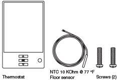
What Is In The Box
Installation
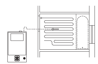
- The floor sensor is recommended placed in an non conductive installation pipe, which is embedded in the floor. The pipe must be sealed in the end and placed as high as possible in the concrete layer.
- The floor sensor must be centered in between the heating cable.
- The power supply voltage must match the voltage rating of the heating cable.
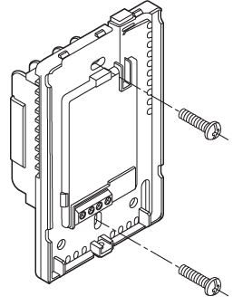
- Loosen the screw at the bottom and remove the faceplate.
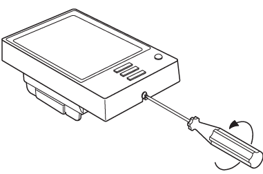
- Do not attempt to remove the screw completely.
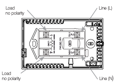
- Turn power source OFF at breaker panel. Connect power supply wires to line side and heating cable wiring to load side of power base. AWG between 12 – 20.
- Note! Do not detach the screws from the terminal. When fastening the screws use a torque between 0.8 – 1.2 Nm / 0.6 – 0.9 lbf-ft.
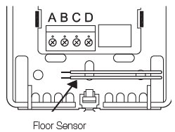
- The floor sensor cable must be routed to the junction box separate from power wires and the heating cable cold lead.
- Ensure that the insulation on the electrical wiring and the floor sensor inside the junction box are not damaged.
- Thread the floor sensor cable through hole in the power base.
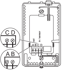
- Install the power base into the electrical box. Make the sensor connections. The Floor sensor has no polarity. Connect it to the terminals C and D The power module connects to the termianals A and B*.
- Refer to the instructions included with the power module.
- Remount the faceplate. Tighten the screw at the bottom. Perform GFCI/EGFPD test

WARNINGS:
- To avoid electric shock, disconnect the heating system power supply at the main panel before installation and maintenance of the thermostat.
- Keep thermostat air vents clean and free from obstruction. This thermostat is an electrical device and must be installed in compliance with national and/or local electrical codes. Installation must be performed by qualified personnel where required by law.
- If a power module with an equipment ground fault protection device (EGFPD) is to be installed where national and/or local electrical codes require a ground fault circuit interrupter (GFCI), a separate GFCI must also be installed.
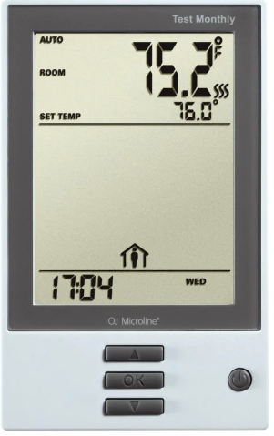
ITEMS
- GFCI/EGFPD Test Button
- Application
- temperature
- Heating indicator – when visible, system is heating.
- Target temperature or setpoint
- 4-Event Program
CLASSIFICATION
The product is a Class II device (reinforced insulation) and must be connected to the following leads:
- Phase L1 (L) 120/208/240 V
- Neutral L2 (N)
- Max. load 15 A (resistive load)
- The thermostat is intended to be used with underfloor heating.
- Heating element in accordance with the supply voltage.
- The terminals are suitable for field wiring cables of 12 to 22 AWG
TECHNICAL DATA
- Supply Range……………………………………………….. 120/240 Vac 50/60 Hz
- Load ………………………………………………………..max. 15 A (resistive load)
- Max. power at e.g. ……………………………………………. 1800 W at 120 Vac
- ………………………………………………………………………. 3120 W at 208 Vac
- ………………………………………………………………………. 3600 W at 240 Vac
- a. UDG (GFCI)…………………………………………….. Class A (5 mA trip level)
- b. ADG (EGFPD)……………………………………………………. (15 mA trip level)
- Temperature range ……………………………… +5 to +40°C / +41 to +104°F
- Amb. temp. range ………………………………….. 0 to +25°C / +32 to +77°F
- Construction of Control………….. Electronic room thermostat
- for regulating electrical underfloor heating.
- Method of Mounting Control………………………… Independently mounted
- control for flush mounting
- Type of Action…………………………………………………………………. Type 2.B.
- Rated Impulse Voltage ……………………… 2500 V
- Control Pollution Degree ……………………………………………………………… 2
- USA – Design Patent No. …………………………………………………………. D768092
- Canada No. ………………………………………………………………………………161353
CERTIFICATION
UL Listed for the US and Canada
According to the following standards:
- Thermostat: UL 60730-1, UL 60730-2-9
- CSA E60730-1, CSA E60730-2-9
- UL file number: E157297
- UDG GFCI: UL 943 4th ed.
- CSA C22.2 No. 144.1-06
- ADG EGFPD UL 1053
- CSA C22.2 No. 0.8
OJ ELECTRONICS A/S
- Stenager 13B · DK-6400 Sønderborg
- Tel.: +45 73 12 13 14
- Fax: +45 73 12 13 13
- [email protected]
- www.ojelectronics.com
REFERENCE:
DOWNLOAD MANUALS:
OJ ELECTRONICS UDG Programmable Thermostat Quick Start Guide
OTHER MANUALS:
OJ ELECTRONICS UDGProgrammable Thermostat Instruction Manual
![]()
OJ ELECTRONICS UDG Programmable Thermostat Quick Start Guide
Leave a Reply