
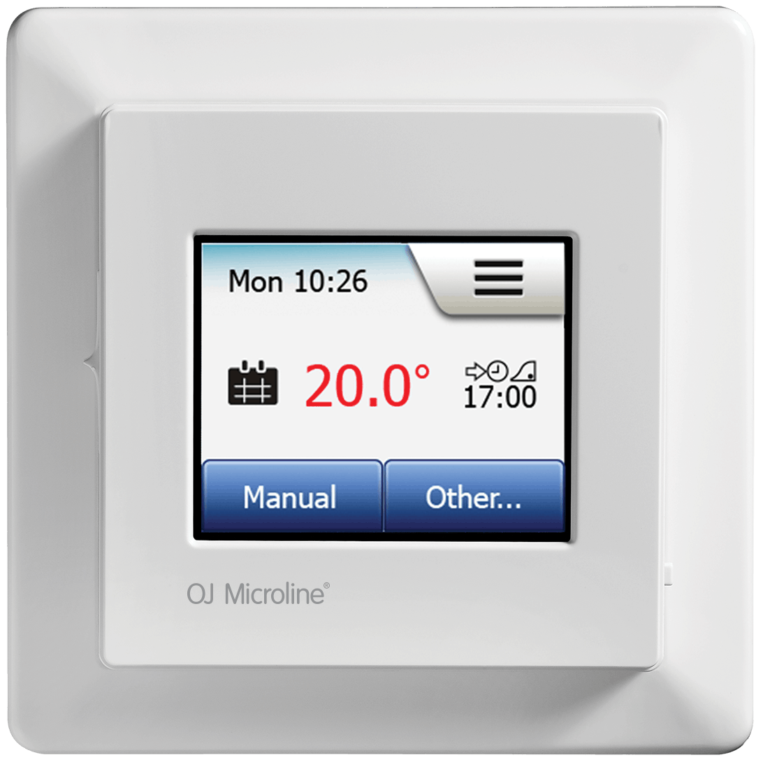
OJ ELECTRONICS MCD5 Touch Thermostat
INTRODUCTION
The thermostat is an electronic PWM/PI thermostat for temperature control by means of an NTC sensor located either externally or internally within the thermostat.
The thermostat is for flush mounting in a wall socket. A baseplate for wall mounting is also available.
This thermostat can be used as a controller for electric room heating pursuant to EN 50559.
PACKAGE CONTENT
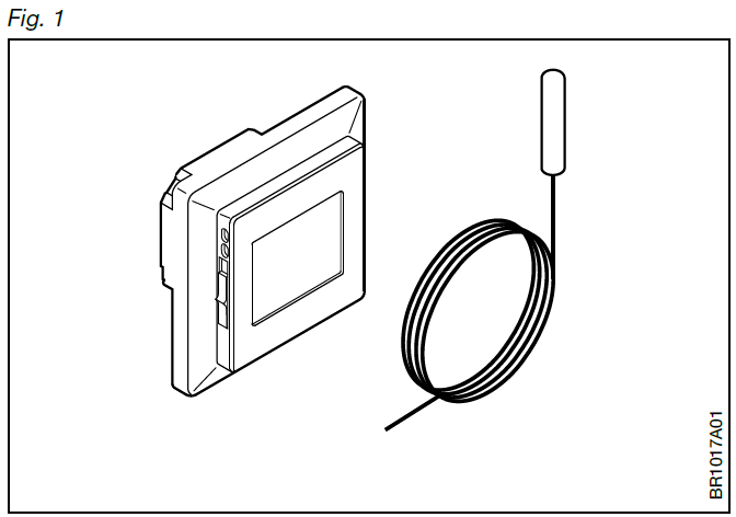
Fig. 1 – Content
- Thermostat
- Sensor
Product program
MCD5-1999-ASP3
- Clock-thermostat with two sensors: floor sensor and built-in room sensor.
IMPORTANT SAFETY INSTRUCTIONS
Fig. 2 – Warnings
To avoid electric shock, disconnect the heating system power supply at the main panel before carrying out any work on this thermostat and associated components.
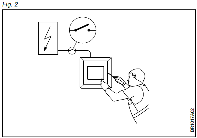
Installation must be carried out by qualified personnel in accordance with appropriate statutory regulations (where required by law). Installation must comply with national and/or local electrical codes.
Cautions
This instruction must be observed, otherwise the liability of the manufacturer shall be voided.
Any changes or modifications made to this thermostat shall void the liability of the manufacturer. Maximum product lifetime is achieved if the product is not turned off but set at the lowest possible set point / frost protection when heat is not required.
Notice
- The language used in the original documentation is English.
- Other language versions are a translation of the original documentation.
The manufacturer cannot be held liable for any errors in the documentation. The manufacturer reserves the right to make alterations without prior notice. Content may vary due to alternative software and/or configurations.
Thermostat placement Mounting of sensor
Fig. 3 – Thermostat placement Mounting of sensor
The floor sensor contains a safety extra-low voltage (SELV) circuit, allowing it to be placed as close to the floor surface as possible without having to take account of the risk of shock should the sensor cable become damaged. The two wires connecting the sensor to the mounting box must be additionally insulated, e.g. shrink flex.

To prevent loose wires in the fixed installation from coming into contact with the terminal block for the floor sensor, they must be restrained using cable ties. It is strongly recommended that the cable and sensor are placed in a non-conductive installation pipe embedded in the floor. The end of the pipe must be sealed and the pipe placed as high as possible in the concrete layer. Alternatively, the sensor can be embedded directly in the floor. The sensor cable must be led through a separate conduit or segregated from power cables.
The floor sensor must be centred between loops of heating cable. The sensor cable may be extended up to 100 m by means of a separate two-core cable. Two vacant wires in a multi-core cable used, for example, to supply current to the floor heating cable must not be used. The switching peaks of such current supply lines may create interference signals that prevent optimum thermostat function. If a shielded cable is used, the shield must not be connected to earth (PE). The two-core cable must be placed in a separate pipe or segregated from power cables in some other way.
Mounting of thermostat with built-in sensor
The room sensor is used for comfort temperature regulation in rooms. The thermostat should be mounted on the wall approx. 1.5 m above the floor in such a way as to allow free air circulation around it. Draughts and direct sunlight or other heat sources must be avoided.
Opening The Thermostat
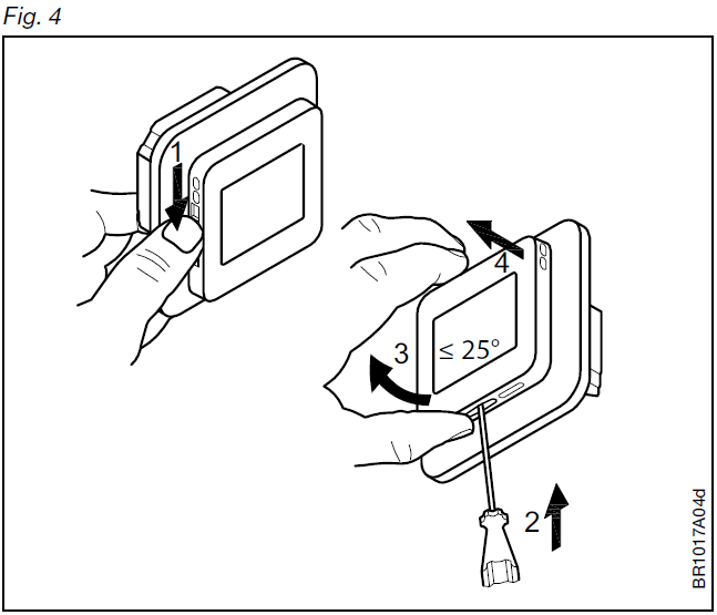
Fig. 4 – Opening the thermostat
- Slide the power button down to Off “0”.
- Release the front cover ONLY by inserting a small screwdriver into the slot at the centre of the bottom side of the front cover to press and hold the catch securing the front cover.
- Then carefully pull the front cover away, initially from the lower part of the thermostat, then from the upper part of the thermostat.
Connections
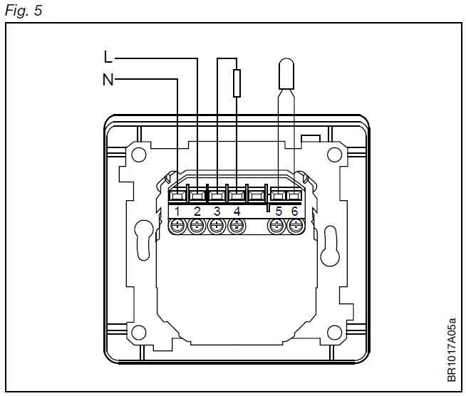
Fig. 5 – Connections
Connect the wires in accordance with the diagram. The wires must be connected as follows:
- Term. 1: Neutral (N)
- Term. 2: Live (L)
- Term. 3-4: Output, max. 16 A
- Term. X: Do not connect
- Term. 5-6: External floor sensor
Mounting The Thermostat
Fig. 6 + 7 – Mounting the thermostat
- Mount the thermostat in the wall socket.
- Fit the frame and carefully press the cover onto the thermostat
- starting with the upper part of the cover, then the lower part of the cover. Ensure that both the power slide button on the cover and the power switch pin in the thermostat are down.
- Click the cover into place by applying light, even pressure.
Warning! Do not apply pressure to the corners of the display cover or to the display itself.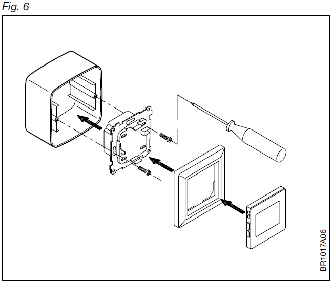
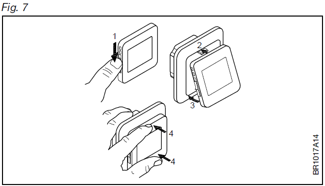
DO NOT open the thermostat by releasing the four fixing clips on the back.
Operating The Thermostat
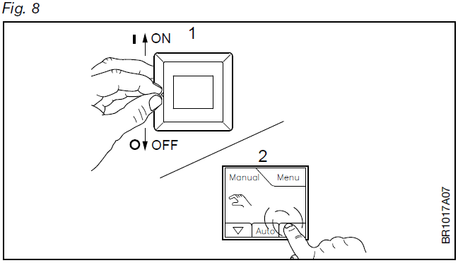
Fig. 8 – Operating the thermostat
- There is an ON/OFF switch on the left side of the thermostat: up is ON – down is OFF.
The resistive touchscreen requires a soft tap with your fingertip to register the touch.
Installer Wizzard:
The first time the thermostat is connected, push the power slide button to On “I” The Installer Wizard on the touchscreen will guide you through the set up of:
- Region
- Language
- Date
- Time
- Floor Type
Programming
See the user manual.

http://www.ojelectronics.com/OCD5
Troubleshooting
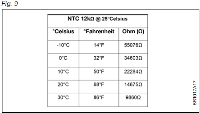
Fig. 9 – Troubleshooting
If the sensor is disconnected or short-circuited, the heating system is switched off. The sensor can be checked against the resistance table.
Error codes
- E0: Internal fault. The thermostat must be replaced.
- E1: Built-in sensor defective or short-circuited. Replace the thermostat, or use the floor sensor only.
- E2: External sensor disconnected, defective or short-circuited. Reconnect the sensor if disconnected, or replace the sensor.
- E5: Internal overheating. Inspect the installation.
MAINTENANCE
The thermostat is maintenance-free.
- Keep the thermostat’s air vents clean and unobstructed at all times.
- The thermostat may only be cleaned with a dry cloth.
APPROVALS AND STANDARDS
Regulations
OJ Electronics A/S hereby declares that the product is in conformity with the following directives of the European Parliament:
- LVD – Low Voltage Directive
- EMC – Electromagnetic Compatibility
- RoHS – Restriction of the use of certain Hazardous Substances
- RED – Radio Equipment Directive
Applied standards and approvals
According to the following standard:
- EN 60730-1, EN 60730-2-9, EN 300 328, EN 301 489-17,
- EN 301 489-1, EN 62479, EN 50559
Classification
Protection from electric shock must be assured by appropriate installation. Must be installed according to the requirements of Class II (reinforced insulation).
ENVIRONMENT AND RECYCLING
Protect the environment by disposing of the package in compliance with local regulations for waste processing.
Recycling of obsolete appliances
Equipment containing electrical components must not be disposed of along with domestic waste. It must be separately collected together with electrical and electronic waste in accordance with current local regulations.
TECHNICAL SPECIFICATIONS
| Purpose of control | Electrical underfloor heating |
| Method of mounting. | Wall mounting in a socket or mounting box |
| Supply voltage | 100-240 VAC ±10% 50/60 Hz |
| Max. pre-fuse | 16 A |
| Built-in interupter | 2-pole, 16 A |
| Enclosure rating | IP 21 |
|
Wire size, terminals |
Current ≤ 13 A – 1.5 mm2, solid core wire
Current > 13 A to 16 A – 2.5 mm2, solid core wire |
| ELV limits realized | SELV 24 VDC |
| Output relay | Make contact – SPST – NO |
| Output, load | Max. 16 A / 3600 W |
| Control principle | PWM/PI |
| Standby consumption | ≤0.5 W |
| Battery backup | 5 years (storage) |
| Battery life, typical | 5 years (storage) 10 years (powered) |
| Dimensions | MxD5: H/84, W/84, D/40 mm |
| Build-in depth | 22mm |
| Weight | ≤200 g |
| Display | 176×220 pixels TFT – resistive touch |
| Control pollution degree | 2 |
| Overvoltage category | III |
| Type of action | 1.B |
| Software class | A |
| Rated impulse voltage | 4kV |
| Ball pressure-temperature (TB) | 125°C |
| EU registered design | DM/082270 |
Note: At very low ambient temperatures the display may respond slowly.
OJ ELECTRONICS A/S
Stenager 13B · DK-6400 Sønderborg Danmark.
The trademark is registered and belongs to OJ Electronics A/S · © 2021 OJ Electronics A/S.
REFERENCE:
DOWNLOAD MANUALS:
OJ ELECTRONICS MCD5 Touch Thermostat Instruction Manual
OTHER MANUALS:
OJ ELECTRONICS MCD5 Touch Thermostat Product Specifications Guide
OJ ELECTRONICS MCD5 Touch Thermostat User Manual
![]()
Leave a Reply