Nexia ACONT624AS42DA Touchscreen Comfort Control Thermostat
Features
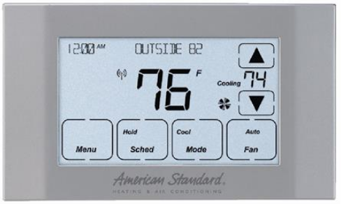
ACONT624AS42DA Features
- 24v, Z-Wave comfort control
- Remote access via smart phone, tablet, or P.C. (requires SK101 and a NexiaTM Home Intelligence account).
- Interactive 4.3” black & white touchscreen
- 7 Day programmable, 4 schedules/day
- Built in humidity sensor with RH display
- Filter, maintenance, humidifier service reminders
- Remote temperature sensing option (1 indoor/1 outdoor)
- Auxiliary & compressor heat lockouts
- Dehumidification (overcooling)
- Enhanced dehumidification (cooling)
- Adjustable variable speed fan settings (pwm)
- Energy Savings Mode (ESM)
- Screen lock and guest lock
- Upgradable firmware (requires a NexiaTM Home Intelligence account).
- Service test modes
- Humidifier control
Operation
The model ACONT624AS42DAA Comfort Control provides typical operation of a forced air heating and cooling HVAC system. The ACONT624 comfort control also features a Z-Wave™ module for remote control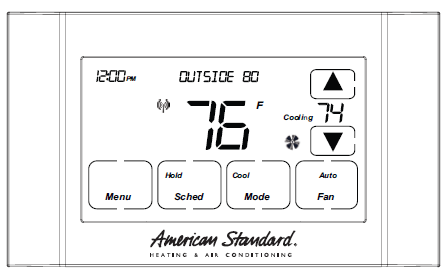
Normally, the Comfort Control displays the Home Screen as shown above.
| Item | Description | Notes |
| Clock Display | The current time is displayed in the upper left corner of the main screen. The time will blink when the clock has not been set. | See TIME/DATE for more information. If the control is connected to Nexia Home Intelligence the clock will be updated by the Nexia portal. |
| Dynamic Labels and Func- tion Control Buttons | The buttons are defined by the dynamic labels in each button. As you navigate through menus, the labels for the buttons will change. | |
| Setpoint Display and Set- point Up/Down Buttons | The current heat or cool setpoint is displayed. These setpoints may be set using Nexia Home Intelligence, the Control’s internal schedule, or by pressing the Set- point Up/Down buttons. Pressing the setpoint button changes the setpoint screen. The current mode is dis- played at the top of the screen. Adjust the setpoint by pressing the up or down arrows. To change setpoint mode press the MODE button. | The setpoints will push each other if they are adjusted to within the minimum heat/cool separation setting.
This is normally 3 degrees. |
| Temperature Display | The Comfort Control displays the current temperature as sensed by the internal temperature sensor. | The internal temperature sensor can be adjusted as necessary. |
| Menu Button | Button used to access other Comfort Control menus | Other Comfort Control menus can be accessed by pressing the MENU button. |
| System Mode Button | Button used to change the system mode | Off: System off Heating: Heating only Cooling: Cooling only
Auto: Heating/Cooling as necessary EM Heat: Indoor Heat only |
| Fan Mode Button | Button used to change the fan mode: | Auto: Fan on when cooling/heating is necessary On: Fan constantly on
Circ: Fan on for a user-selected number of minutes per hour. |
| Schedule Mode Button | Button used to change the schedule mode: | Hold: System maintains the current temperature set- points. Schedules are disregarded.
Run: Run the system schedule Energy Saving Mode (ESM): Temperature setpoints in ESM Setpoints are maintained. |
User Settings
| Thermostat | ||
| Setting | Range | Description |
| Temperature Scale | [Fahrenheit], Celsius | Select the temperature display scale |
| Cooling RH Setpoint | 30% – 60% [50%] | Select the desired indoor relative humidity during cooling mode. Dehu- midification must be enabled in the Installer Settings for this option to be available. |
| Heating RH Setpoint | 10% – 45% [40%] | Select the desired indoor relative humidity during heating mode. Humidification must be enabled in the Installer Settings for this option to be available. |
| Smart Continuous Fan | Yes, [No] | If yes is selected, continuous fan mode is disabled when indoor humidity exceeds the Cooling RH Setpoint |
| Continuous Fan Airflow | 35% – 100% [50%] | Select the desired fan speed when the Fan Mode selected is Continuous (variable speed blower required) |
| Fan Circulate On Time | 1 – 59 minutes, [Off] | Select the desired amount of time the fan will cycle per hour when the Fan Mode selected is Circ |
| Local Schedule Enable | [Yes], No | Select whether scheduling will be enabled or disabled |
| Max Heat Setpoint | 55 – [90] Degrees | Select the highest heating setpoint allowed |
| Min Cooling Setpoint | [60] – 99 Degrees | Select the lowest cooling setpoint allowed |
| H/C Delta | [3] – 15 Degrees | Select the minimum deadband between Heating and Cooling setpoints |
| Once all selections have been made, press the Done button to exit and return to Menu. Press Next to navigate to the next setting. | ||
| Energy Savings Mode | ||
| Setting | Range | Description |
| ESM Heat Setpoint | 55 – 90 degrees [62] | Select the desired Heating Setpoint when ESM (Energy Savings Mode) is selected |
| ESM Cooling Setpoint | 60 – 99 Degrees [85] | Select the desired Cooling Setpoint when ESM (Energy Savings Mode) is selected |
| Once all selections have been made, press the Done button to exit and return to Menu. Press Next to navigate to the next setting. | ||
| Display | ||
| Setting | Range | Description |
| Screen Timeout | [0] – 90 Seconds | Select how long after the last button press before the screen timeouts to a minimized screen |
| Backlight Timeout | 0 – 90 Seconds [20] | Select how long after the last button press before the backlight dims |
| Backlight On Percent | 0 – [100] Percent | Select the screen brightness when the backlight is lit |
| Backlight Off Percent | [0] – 100 Percent | Select the screen brightness when the backlight timeout expires |
| Buzzer Enable | [Yes], No | Select whether button presses are audible |
| Security | [Unlocked], Display Lock, Guest Access | Select security level
• Unlocked – Enables selection of all menus and settings • Display Lock – Disables selection of all menus and settings • Guest Access – Disables selection of all menus and settings except the following: Raise or lower heating or cooling setpoint +/- 5 degrees and change system mode Note: When Display Lock or Guest Lock is selected a lock icon will appear next to the up arrow. Note: To disable Display Lock or Guest Access, press and hold the up and down arrows until the lock icon disappears. |
| Once all selections have been made, press the Done button to exit and return to Menu. Press Next to navigate to the next setting. | ||
| Time/Date | ||
| Setting | Range | Description |
| Hour | 1 – 12 am, 1 – 12 pm | Select the current hour of day |
| Minutes | 0 – 59 | Select current minute of day |
| Day of Week | Sun – Sat | Select current day of week |
| Year | 2013 – 2113 | Select current year |
| Month | Jan – Dec | Select current month of year |
| Date | 1 – 31 | Select current day of month |
| Once all selections have been made, press the Done button to exit and return to Menu. Press Next to navigate to the next setting. | ||
| Reminders | ||
| Setting | Range | Description |
| Filtration Enable | Yes, [No] | Selecting yes, enables the Filter Reminder feature |
| Filter Period | [Monthly], Quarterly, Semi-Annu- ally, Annually | Select how often the reminder will be displayed |
| Filter Start Month | [Jan] – Dec | Select the Filter Reminder start month |
| System Maint Enable | Yes, [No] | Selecting yes, enables the System Maintenance Reminder feature |
| First Maint Month | Jan – Dec | Select the first System Maintenance month |
| Second Maint Month | Jan – Dec | Select the second System Maintenance month |
| Once all selections have been made, press the Done button to exit and return to Menu. Press Next to navigate to the next setting. | ||
Scheduling
Schedule Setup Procedure
The 624 comfort control is preset at the factory with a 7 Day energy savings schedule. Each day of the week is pre-programmed with the following schedule:
| Scheduling | |||
| Time | Schedule Name | Heat Temperature Setting | Cool Temperature Setting |
| 6:00 AM | Wake | 70 F | 78 F |
| 8:00 AM | Day | 62 F | 85 F |
| 6:00 PM | Evening | 70 F | 78 F |
| 10:00 PM | Night | 62 F | 78 F |
| The schedule may be changed locally at the control with the Edit Schedule menu. If the 624 comfort control is connected to Nexia Home Intelligence the schedule may be changed remotely from the Nexia website using the website’s Edit Schedule menu. | |||
Edit Schedule (Local)
Press the following button sequence to edit or create an entirely new daily schedule.
| Edit Schedule | ||
| Button Press | Menu Displayed | What Needs to Be Done? |
| Press Menu from Home screen | USER SETTINGS | |
| Press Next | SCHEDULE | |
| Press Select | EDIT SCHEDULE | |
| Press Select | SELECT DAY | Continue to press “Next” until the day of week to edit is displayed. |
| Press Select | SET TIME | Set the start time for each of four periods for the day displayed. Use the Up/Down buttons to set the start time for the period displayed. Wake is the default period. Pressing the “Next” button three times cycles through the period displayed (Wake, Day, Evening and Night). |
| Press Next | HEAT SETPOINT | Use the Up/Down arrows to set the Heat set point for the period displayed |
| Press Next | COOL SETPOINT | Use the Up/Down arrows to set the Heat set point for the period displayed |
| Press Next | Continue pressing Next and using up/down arrows until all Heat & Cool set points are set for the day displayed. After editing a start time or editing the set point temperature for one or more periods press “Done” to save edits. If “Done” is not pressed edits will not be saved. | |
| After Pressing Done | Copy Schedule is dis- played at the top of the screen. Yes
and No buttons are dis- played on the right side of the screen. |
Press yes to copy or no to return to Edit Schedule menu. |
| Press Yes to Copy | COPY “_ _ _” To is displayed at the top of the screen. Yes and No buttons are displayed on the right side of the screen. | Pressing Yes will copy the day displayed to the next day in the week. If Yes is pressed five more times the scheduled will be copied to the remaining 5 days in the week. To skip over a day and avoid copying the schedule to that day press No. |
| Press Done | EDIT SCHEDULE
menu is displayed |
To return to the Home Screen press “Done” one more time. |
| Press Done | Home Screen is displayed | |
| The schedule may be changed locally at the control with the Edit Schedule menu. If the 624 comfort control is connected to Nexia Home Intelligence the schedule may be changed remotely from the Nexia website using the websites Edit Schedule menu. | ||
Copying Schedules
Press the following button sequence to access “Copying Schedules” from the Home Screen.
| Copying Schedules | ||
| Button Press | Menu Displayed | What Needs to Be Done? |
| Menu | ||
| Next | USER SETTINGS screen | |
| Select | EDIT SCHEDULE screen | |
| Next | COPY SCHEDULE screen | |
| Select | COPY FROM screen (Mon) | Defaults to Monday |
| Next | Advances to next day | |
| Back | Goes back to previous day | |
| Select | Copy To screen | Select the day to copy to by pressing on Yes or No buttons until the copy to day is selected. |
| Press Done | COPY SCHEDULE | Continue copying one days schedule at a time to another or Press Done until the Home Screen Appears |
| Press Done | SCHEDULE | |
| Press Done | HOME SCREEN is dis- played | |
| Press Done | Home Screen is displayed | |
| The schedule may be changed locally at the control with the Edit Schedule menu. If the 624 comfort control is connected to Nexia Home Intelligence the schedule may be changed remotely from the Nexia website using the websites Edit Schedule menu. | ||
Edit Schedule (Remotely) – from Nexia Home Intelligence
Go to MyNexia.com, log into your account and select a ACONT624 comfort control from the Climate Page. Click on Edit Schedule and follow the online instructions. If you have not set up a Nexia Home Intelligence account go to MyNexia.com and click on “Get Started” to set up an account. A router and Nexia Bridge kit (SK101 – includes one Nexia Bridge and one Z-wave module) is required for remote access to the 624 control. For questions about connecting to Nexia Home Intelligence contact Nexia Home Intelligence Customer Service at 877-288-7707
Enroll Comfort Control into existing Z-Wave Network (NexiaTM Home Intelligence)
Prepare the bridge for enrollment. (Bridge kit SK101 purchased separately)
Note: If the bridge is already installed, follow the instructions as they are written in the following steps. If the bridge is not installed, follow the instructions shipped with the bridge kit.
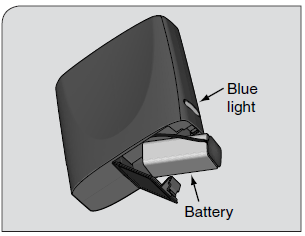
- Unplug Ethernet and power cables from bridge.
- Install a quality 9 volt battery.
- Verify that blue light is blinking. If blue light is solid, battery is dead.
- Take bridge to the location where the Comfort Control is mounted.
Enroll the Comfort Control into the bridge. (Inclusion)
- If you are using a controller that is not a NexiaTM bridge, consult the instructions that shipped with the controller to find out how to enroll a new device.
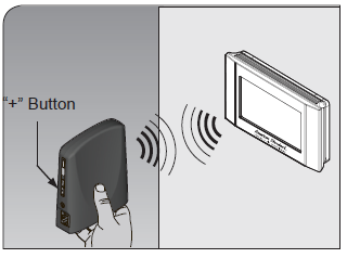
- Hold the bridge within 6 feet (1.8 meters) of the Comfort Control throughout steps “b” through “f”.
- After you begin the enrollment process, you have 30 seconds to complete the remainder of the steps. Study the steps below before beginning.
- Press and release the plus (+) button on the bridge.
- Press the MENU button on the Comfort Control.
- Press the NEXT button to advance to the Z-WAVE menu.
- Press SELECT
- Observe the lights on the bridge. The orange light will blink while enrollment is taking place. Enrollment is complete when the orange light becomes solid
Verify enrollment of the Comfort Control.
- Press Menu Button on the main Comfort Control screen.
- Press the Next Button to advance to the About screen and press the Select Button.
- Press the Next Button to advance through the menu options to Node ID
- If the number listed there is anything other than “00”, the Comfort Control has been successfully enrolled.
- If the number listed there is “00”, the Comfort Control has NOT been successfully enrolled. In this case, repeat step 18 and verify again.
- Press Done button 2 times when finished.
| Item | Description |
| VERSION 010000 | Firmware version (number may vary) |
| ZWAVE VER 034006 | Z-Wave version (number may vary) |
| NODE-ID 01 | Z-Wave node ID (number may vary) |
| HOME-ID 00000000 | Z-Wave Home ID (number may vary) |
| OUT-TYPE AC | Outdoor type may be AC, HP or NONE |
| C/O WITH COOL | Energize Reversing Valve with COOL or with HEAT (HP only) |
| IN-TYPE GAS/OIL | Indoor type may be GAS/OIL, ELECTRIC or HYDRONIC |
Establish Online Connection to the Comfort Control.
- Nexia Home Intelligence account must be active before continuing. See nexiahome.com for more information.
- Remove the battery from the bridge.
- Plug the Ethernet and power cord back into the bridge.
- Log into your account at www.mynexia.com
- Click the Climate tab and follow the on screen instructions.
Un-enroll Comfort Control from existing Z-Wave Network (NexiaTM Home Intelligence)
If you need to remove the 624 from a Nexia Home Intelligence account, follow the Exclusion steps. This will delete the ability to control the thermostat remotely. If you are unsure, please contact Nexia support at
877-288-7707.
Install a new, high-quality 9-volt battery into the bridge.
- Hold the bridge within 6 feet (1.8 meters) of the Comfort Control throughout the entire exclusion process.
- After you begin the exclusion process, you have 30 seconds to complete the remainder of the steps. Study the steps below before beginning.
- Press and release the minus (-) button on the bridge.
- Press the MENU button on the Comfort Control.
- Press NEXT button to scroll to Z-WAVE screen then press SELECT.
- Press the Yes button to exclude the Comfort Control.
- Observe the lights on the bridge. The orange light will blink while exclusion is taking place. Exclusion is complete when the orange light becomes solid.
- Z-Wave™ controllers from various manufacturers may support the Z-Wave™ Thermostat General V2 Device class used by the Z-Wave™ Comfort Control. If you are using a controller that is not a Nexia bridge, consult the instructions that came with the controller to find out how to enroll a new device.
Firmware Upgrades
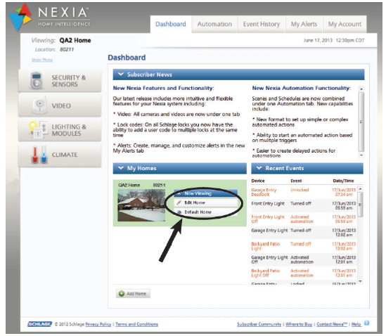
- Firmware Upgrades allow the user to update the 624 control. Upgrades may take up to 45 minutes. The system operation will be maintained during the upgrade process. To access the Firmware Upgrades navigate to mynexia.com and look for the Edit Home screen button. The Edit Home screen button is located about mid way down the Nexia Home Page.
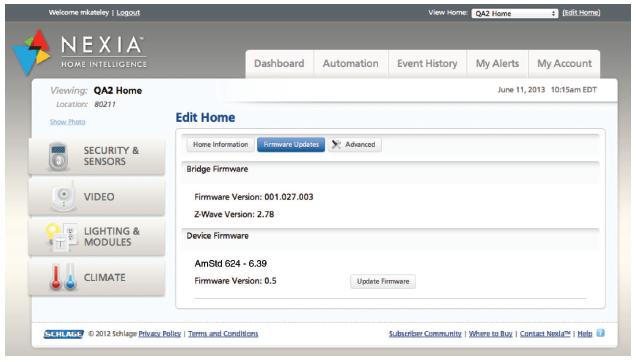
- On the Edit Home, Firrmware Updates page, the 624 will appear. If a firmware update is available an”Update Firmware” button will appear.
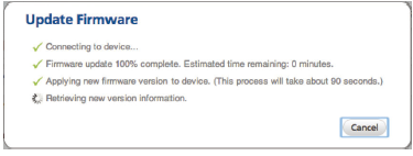
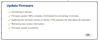
 When the user selects the “Update Firmware” button an “Update Firmware” dialog will appear. The dialog will first connect to the device and then it will display the firmware update progress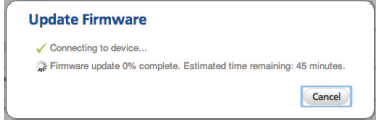
- After the firmware has been downloaded it is then applied to the ACONT624
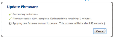
- The portal retrieves version information from the ACONT624
- Finally the user is shown that the firmware was updated successfully
About
| About | |
| Setting | Range |
| Version | Current firmware version loaded on the control |
| ZWAVE Ver | Current version of the ZWAVE firmware |
| Node – ID | ZWAVE identification for this device |
| Home – ID | ZWAVE identification for the connected ZWAVE network |
| Out – Type | Identifies the type of outdoor unit installed |
| C/O – Type | Indicates whether the switchover valve (SOV) is energized in cooling or heating mode |
| In – Type | Identifies the type of indoor unit installed |
| Once all selections have been made, press the Done button to exit and return to Menu. Press Next to navigate to the next setting. | |
Clean Screen
| Clean Screen | ||
| Setting | Range | Description |
| Clean Screen | Yes, No | Selecting yes allows the user to clean the screen without activating any of the onscreen touch points. Use only water and a soft cloth, no harmful chemicals. |
| Once all selections have been made, press the Done button to exit and return to Menu. Press Next to navigate to the next setting. | ||
Product Specifications
| Product Specifications | |||
| Specification | Description | ||
| Product Model: | ACONT624AS42DAA | ||
| Product: | HVAC System comfort control. Z-Wave™ RF communications enabled | ||
| Size: | 5.75” wide x 3.5” height x 1” depth | ||
| Display: | Fixed Segment LCD, 4” x 2.25”, with 17 character alpha numeric display | ||
| Touchscreen: | Yes. | ||
| Backlight: | Yes, White, Controllable, on, off, timeout | ||
| Power: | 24VAC from HVAC System | ||
| HVAC System Type: | Standard (gas/electric), Heat Pump, or Dual Fuel | ||
| Heat/Cool Stages: | Up to four stages of heat/two stages cool | ||
| PWM Output (BK) | Proprietary Variable speed motor control | ||
| Heat Pump Switchover valve: | Selectable change over with cool or with heat | ||
| Auxiliary Contact | Humidifier, Ventilation or Dehumidifier control | ||
| Communications: | Z-Wave™ RF | ||
| Memory: | Non-volatile | ||
| Date/Time: | 24 hour super capacitor backup
Time is automatically updated if the control is connected to NEXIA home intelligence |
||
Installation and Wiring
When this Comfort Control is replacing an old thermostat that contains mercury in a sealed tube, do not dispose of your old thermostat in the trash. Dispose of properly. Contact your local waste management authority for instructions regarding recycling and proper disposal of the old thermostat. A listing of heating, ventilating and air conditioning wholesalers that participate in the Thermostat Recycling Corporation’s recycling program are available at www.thermostat-recyle.org.
Physical Location
Temperature Sensing Considerations
The 624 Control is designed for installation in climate controlled living spaces. It is recommended to place the unit in central locations with good circulation. Avoid exterior walls and areas near windows, doors, vents or concealed pipes or chimneys.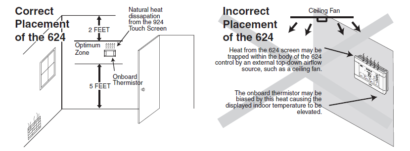
Installer’s Guide
CAUTION: Before proceeding with installation, verify system power has been removed.
- Separate the face of the new Comfort Control from the wall plate.
- Apply pressure at two tabs on top of wall plate to release it.
- NOTE: It is not recommended that this Z-waveTM Comfort Control be mounted onto metal structures. Metal may adversely affect the radio frequency (RF) communication between the Comfort Control and the Z-waveTM bridge.
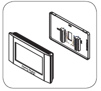
Mark two mounting holes using new wall plate.
- Pull wires through hole in center of wall plate.
- Locate the new wall plate over existing opening.
- Mark two holes with pencil.
- Use a level to verify that the two hole locations are level.
- Correct hole locations as needed.
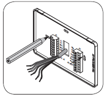
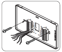
Install new wall plate.
- Pull wires through hole in center of wall plate.
- Locate the new wall plate over existing opening.
- Attach wall plate to wall using two screws provided. Do not over tighten.
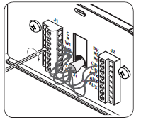
Attach all wires securely to the new Comfort Control.
(See the Field Wiring Diagrams on the following pages.)
- Note: A wire must be connected to “C” to power the Comfort Control.
- Use the information from the Field Wiring Diagrams to match the wires to the correct terminals.
- Use 1/8” blade screwdriver to secure wires in terminals.
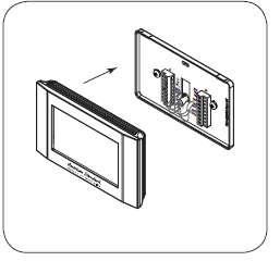
Attach the Comfort Control face to the wall plate.
- Carefully align the face plate to the wall plate while aligning pins into wire terminals.
- Once Comfort Control face is properly aligned, apply pressure at top and bottom of Comfort Control face until it is secure
Turn power to heating and cooling system back on.
- The Comfort Control display should turn on and begin displaying information.
- Proceed to Installer’s Setup to configure system settings
Heat/Cool Wiring Diagrams
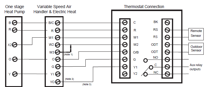
Heat/Cool Diagram 1: 1 or 2 Stage Cooling w/TAM7 Model Variable Speed Air Handler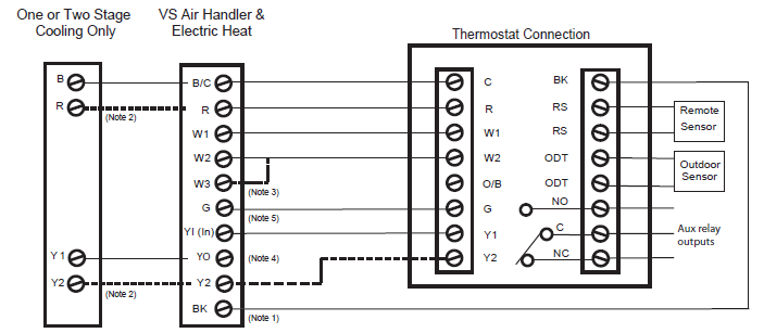 Heat/Cool Diagram 2: 1 Stage Cooling w/“GAM5A” & “TAM4” Model Air Handler
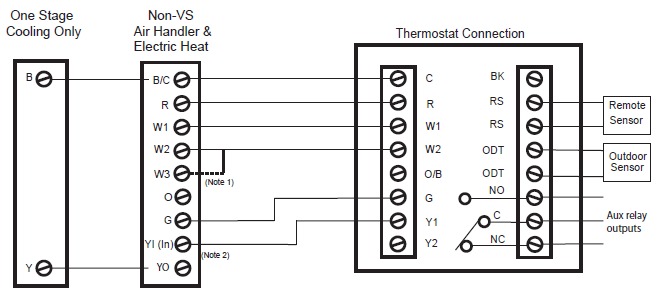
Heat/Cool Diagram 3: 1 Stage Cooling w/“GAM5B” Model Air Handler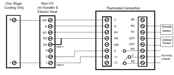
Heat/Cool Diagram 4: 2 Step Cooling w/“GAM5B” Model Air Handler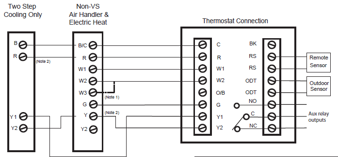
Heat/Cool Diagram 5: 1 Stage Cooling w/“GAF2-S” Model Air Handler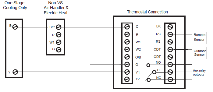 Heat/Cool Diagram 6: 1 stage cooling w/“GAF2-36M” Model Air Handler
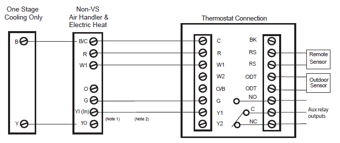
Heat/Cool Diagram 7: 1 Stage Cooling w/”GAT2” & “GAM2” Model Air Handlers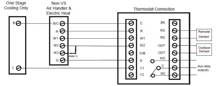 Heat/Cool Diagram 8: 1 Stage Cooling w/“TEM3” Model Air Handler
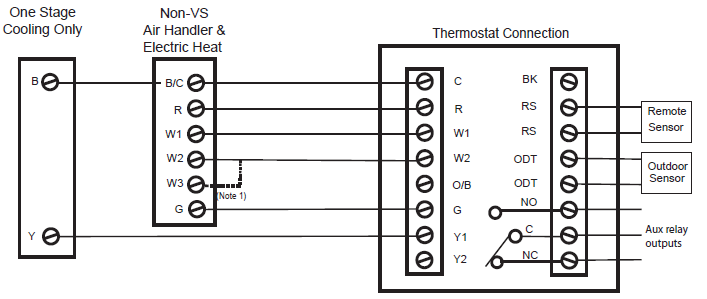
Heat/Cool Diagram 9: 1 or 2 Stage Cooling w/non-TAM7 Model Variable Speed Air Handler
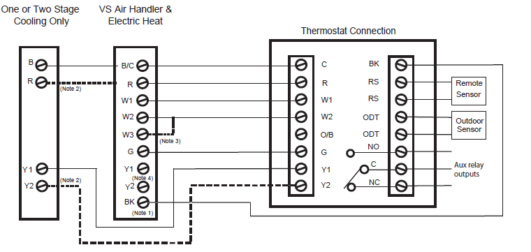
Heat/Cool Diagram 10: 1 Stage Cooling w/non-variable Speed Air Handler(Excludes Hyperion/Forefront/TEM3 Air Handlers)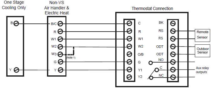
Heat/Cool Diagram 11: 1 Stage Cooling w/non-Variable Speed Gas Furnace
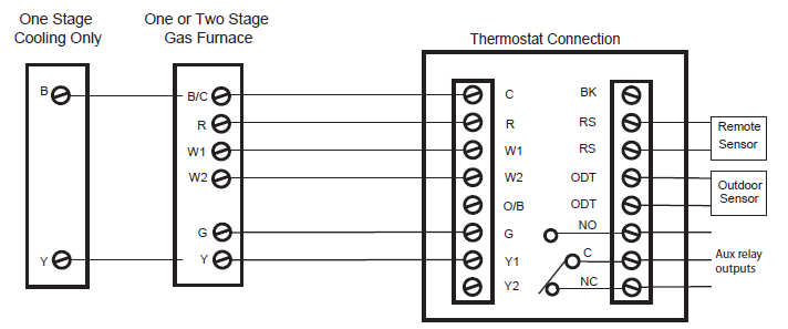
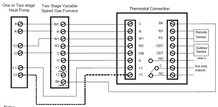
Heat/Cool Diagram 12: 1 or 2 Stage Cooling w/Variable Speed Gas Furnace

Heat/Cool Diagram 13: 1 Stage Cooling w/non-Variable Speed Oil Furnace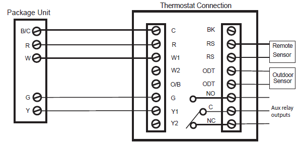
Heat/Cool Diagram 14: 1 or 2 Stage Cooling w/Variable Speed Oil Furnace

Heat/Cool Diagram 15: Package Single or Multi-Stage Gas/Electric with Variable Speed Blower
Heat/Cool Diagram 16: Package Single Stage Gas/Electric with non-Variable Speed Blower 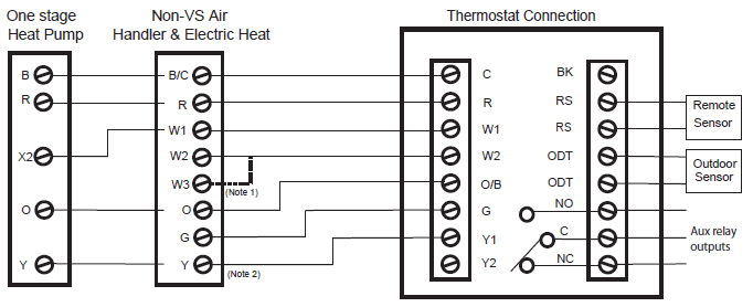
Heat Pump Wiring Diagrams
Heat Pump Diagram 1: 1 or 2 Stage Heat Pump w/TAM7 Model Variable Speed Air Handler
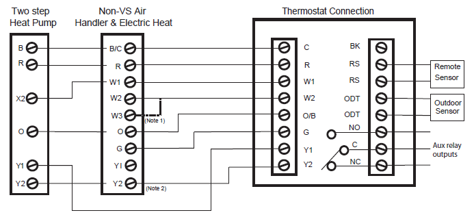
Heat Pump Diagram 2: 1 Stage Heat Pump w/”GAM5A” & “TAM4” Model Air Handler
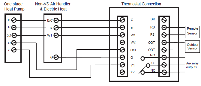
Heat Pump Diagram 3: 1 Stage Heat Pump w/”GAM5B” Model Air Handler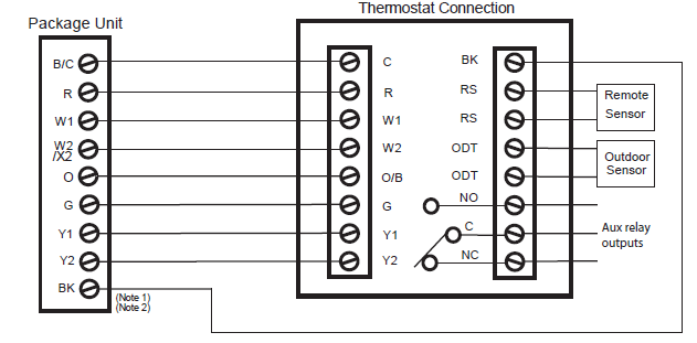
Heat Pump Diagram 4: 2 Step Heat Pump w/”GAM5B” Model Air Handler
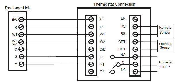
Heat Pump Diagram 5: 1 Stage Heat Pump w/”GAF2-S” Model Air Handler
Heat Pump Diagram 6: 1 Stage Heat Pump w/”GAF2-36M” Model Air Handler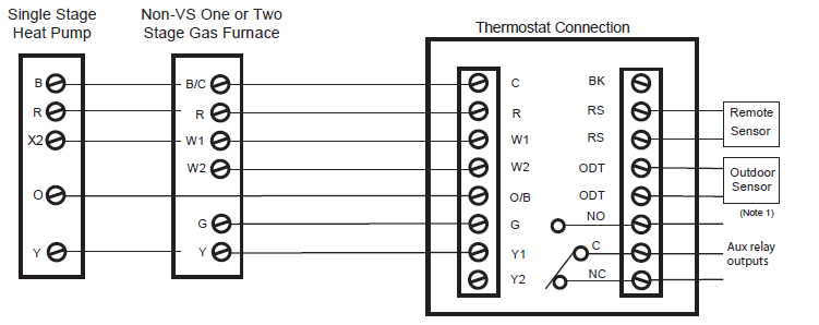
Heat Pump Diagram 7: 1 Stage Heat Pump w/”GAT2” & “GAM2” Model Air Handler
Heat Pump Diagram 8: 1 Stage Heat Pump w/”TEM3” Model Air Handler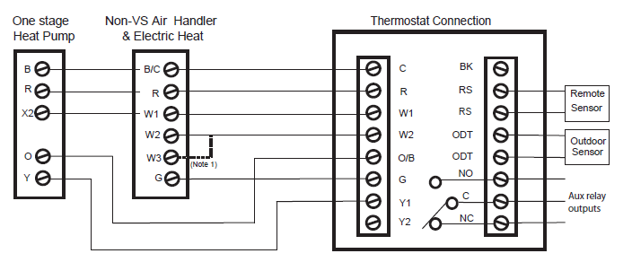
Heat Pump Diagram 9: 1 or 2 Stage Heat Pump w/non-TAM7 Model Variable Speed Air Handler
Heat Pump Diagram 10: 1 Stage Heat Pump w/non-Variable Speed Air Handler (Excludes Hyperion/Forefront/TEM3 Air Handlers)
Heat Pump Diagram 11: Package Single or Multi-stage Heat Pump with Variable Speed Blower
Heat Pump Diagram 12: Package Heat Pump with non-Variable Speed Blower
Dual Fuel Wiring Diagrams
Dual Fuel Diagram 1: 1 or 2 Stage Heat Pump w/Variable Speed Gas Furnace
Dual Fuel Diagram 2: 1 Stage Heat Pump w/non-Variable Speed Gas Furnace
Dual Fuel Diagram 3: 1 or 2 Stage Heat Pump w/Variable Speed Oil Furnace
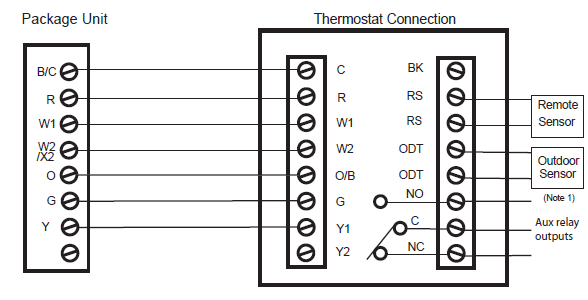
Dual Fuel Diagram 4 : 1 Stage Heat Pump w/non-Variable Speed Oil Furnace
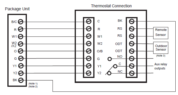
Dual Fuel Diagram 5: Package Single or Multi-Stage Dual Fuel with Variable Speed Blower
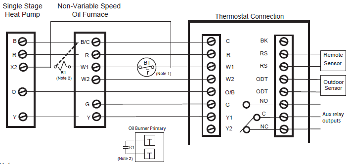
Dual Fuel Diagram 6: Package Single Stage Dual Fuel with Non-Variable Speed Blower
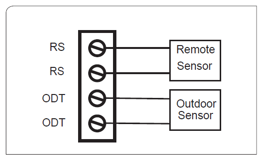
Optional Remote Temperature Sensors Installation
Wire specification for remote sensors: 2 conductors, 18 gauge wire. Make sure that the sensor wires are installed in a separate cable from the wiring to the HVAC system. Best results for distances of 100 feet or less. Accuracy may be affected for distances up to a maximum of 200 feet. Shielded cable is recommended for distances over 100 feet and less than 200 feet.
CAUTION: Keep this wiring at least one foot away from large inductive loads such as electronic air cleaners, motors, line starters, lightning ballasts, and large distribution panels. Failure to follow these wiring practices may introduce electrical interference (noise) which can cause erratic system operation. Shielded cable is required if the above wiring guidelines cannot be met. Be sure to ground only one end of the shield to the Comfort Control common terminal. Tape back the other end of the shield.
Remote Sensors Part Numbers
- Remote Indoor Sensor: Use ZZSENSAL0400AA for indoor applications.
- Remote Outdoor Sensor: Use BAYSEN01ATEMPA for outdoor applications.
- > IMPORTANT: Make sure that the sensor wires are installed in a separate cable from the Comfort Control cable.
- > IMPORTANT: Follow directions below for averaging. These instructions replace the averaging information found in the Installer’s Guide for the ZZSENSAL0400AA.
Remote Temperature Sensor Connections and Operation:
- Indoor sensor connected to RS.
- The Remote Sensor (RS) function can be configured in the Service/Installer Settings/Sensor Settings menu. Options are:
- None
- Replaces onboard temp sensor of the Comfort Control
- Averages with onboard temp sensor
- Replace – RS Sensor replaces the internal temperature sensor of the Comfort Control. This allows the Comfort Control to be installed in a location different than the area where the temperature will be measured. Use ZZSENSAL0400AA.
- Average – RS Sensor averages its temperatures with the internal sensor. Use ZZSENSAL0400AA.
- The Remote Sensor (RS) function can be configured in the Service/Installer Settings/Sensor Settings menu. Options are:
- B) Outdoor sensor connected to ODT. Reports outdoor temperature to the Comfort Control.
- The Outdoor Sensor (ODT) function can be configured in the Service/Installer Settings/Sensor Settings menu. Options are:
- None
- Outside
- Outside – ODT (outdoor temperature sensor). If ODT sensor is selected and connected, the outdoor temp is displayed on the main screen. ODT model is BAYSEN01ATEMPA
- The Outdoor Sensor (ODT) function can be configured in the Service/Installer Settings/Sensor Settings menu. Options are:
Installer’s Setup
| Equipment Type | ||
| Setting | Range | Description |
| Outdoor Unit Type | None, [AC], HP | Select the type of outdoor unit installed |
| Outdoor Unit Stages | [1], 2 | Select the number of outdoor unit stages |
| Compressor Type | 1 Comp – 2 Stage,
[2 Comp – 2 Stage] |
Select the compressor type for multi-stage outdoor units |
| Indoor Unit Type | [Gas/Oil], Electric, Hydronic | Select the type of indoor unit installed |
| Hydronic Type | [Hydro Air], Wet Heat | Select the type of hydronic heat operation. Hydro Air selection interlocks the blower during an active call for indoor heat. Wet Heat selection dis- ables indoor fan operation on an active call for indoor heat. |
| Indoor Heat Stages | [1], 2 | Select the number of indoor heat stages |
| Indoor Blower Type | [Non – Variable], Variable | Select the indoor blower type (Constant Torque motors are considered non-variable speed) |
| Energize Reversing Valve | [With Cool], With Heat | Select whether Reversing Valve is energized in cooling or heating mode |
| Once all selections have been made, press the Done button to exit and return to Menu. Press Next to navigate to the next setting. | ||
| Equipment Settings | ||
| Setting | Range | Description |
| Compressor Stage 1 MRT | [3] – 9 Minutes | Select the minimum runtime (MRT) of stage 1 compressor operation |
| Compressor Stage 2 MRT | [3] – 9 Minutes | Select the minimum runtime (MRT) of stage 2 compressor operation |
| Compressor MOT | [5] – 9 minutes | Select the minimum offtime (MOT) for compressor operation |
| Indoor Heat Stage 1 MRT | [3] – 9 Minutes | Select the minimum runtime (MRT) of stage 1 indoor heat |
| Indoor Heat Stage 2 MRT | [3] – 9 Minutes | Select the minimum runtime (MRT) of stage 2 indoor heat |
| Indoor Heat MOT | [5] – 9 minutes | Select the minimum offtime (MOT) for indoor heat operation |
| Once all selections have been made, press the Done button to exit and return to Menu. Press Next to navigate to the next setting. | ||
| Sensor Settings | ||
| Setting | Range | Description |
| Sensor Calibration | *-7 – +7 Degrees [0] | Calibrate the indoor temperature sensor (do not attempt to calibrate the indoor temperature within the 1st hour upon power-up) |
| Remote Sensor | [None], Replace Indoor, Average | Select whether a remote indoor temperature sensor has been connected, and if a remote sensor has been connected, indicate whether to use the re- mote sensor to replace the onboard temperature sensor or average the two. |
| Remote Sensor Calibration | *-7 – +7 Degrees [0] | Calibrate the remote temperature sensor |
| Outdoor Sensor | [None], Outdoor | Select whether an outdoor temperature sensor has been connected |
| Outdoor Sensor Calibration | *-7 – +7 Degrees [0] | Calibrate the outdoor temperature sensor |
| RH Calibration | *-7% – +7% [0] | Calibrate the RH sensor |
| Once all selections have been made, press the Done button to exit and return to Menu. Press Next to navigate to the next setting. | ||
| Accessories | ||
| Setting | Range | Description |
| Aux Relay | [None], Humidifier, Ventilation, Dehumidifier | Select what accessory the Aux Relay is controlling |
| Humidifier Control Options | With Active Heat, [w/o Active Heat] | Select whether the humidifier is allowed to operate with an active call for heat only or stand-alone operation (humidifier operates independent from heating operation) |
| Ventilation On Timer | [Off], 1 – 60 Minutes | Select the minimum runtime per hour of the ventilation equipment |
| Once all selections have been made, press the Done button to exit and return to Menu. Press Next to navigate to the next setting. | ||
| Comfort Setting | ||
| Setting | Range | Description |
| Enhanced Dehumidification | [Yes], No | When dehumidification is enabled, the control will reduce system airflow by 30% (variable speed indoor units only) anytime the indoor humidity is higher than the cooling target humidity setpoint and the indoor temperature is within 2°F of cooling setpoint. All fan off delays will also be cancelled. |
| Dehumidification Overcooling
Limit |
[Off], 1, 2, 3 Degree | Select the maximum amount of overcooling allowed when the indoor humidity exceeds the cooling target humidity setpoint. To accomplish the overcooling the control will artificially create additional load by increas- ing the sensed indoor temperature by 1/10th of a degree for every 1% of humidity error, up to the overcooling limit selected. The displayed indoor
temperature will remain the same, but the adjusted indoor temperature will control cooling operation. |
| HP Warm Air Discharge | Yes, [No] | When enabled the indoor blower speed will be limited to 80% on a call for heat pump heating. This only applied to heat pump heating with no call for aux heat. An indoor unit with variable speed blower is required. |
| Comp Heat Delta Stage 1 On | .5 – 8 Degree | Select the delta on for 1st stage compressor heat |
| Comp Heat Delta Stage 2 On | 1 – 8 Degree | Select the delta on for 2nd stage compressor heat |
| Indoor Heat Delta Stage 1 On | .5 – 8 Degree | Select the delta on for 1st stage indoor heat |
| Indoor Heat Delta Stage 2 On | 1 – 8 Degree | Select the delta on for 2nd stage indoor heat |
| Comp Heat Delta Stage 1 Off | 0 – 8 Degree | Select the delta off for 1st stage compressor heat |
| Comp Heat Delta Stage 2 Off | 0 – 8 Degree | Select the delta off for 2nd stage compressor heat |
| Indoor Heat Delta Stage 1 Off | 0 – 8 Degree | Select the delta off for 1st stage indoor heat |
| Indoor Heat Delta Stage 2 Off | 0 – 8 Degree | Select the delta off for 2nd stage indoor heat |
| Cooling Delta Stage 1 On | .5 – 8 Degree | Select the delta on for 1st stage cooling |
| Cooling Delta Stage 2 On | 1 – 8 Degree | Select the delta on for 2nd stage cooling |
| Cooling Delta Stage 1 Off | (-) 2 – (+)6 | Select the delta off for 1st stage cooling |
| Cooling Delta Stage 2 Off | 0 – 7 | Select the delta off for 2nd stage cooling |
| Heat Stage Up Timer | [Off], 5 – 60 Minutes | Select the amount of time that 1st stage can operate before transitioning to 2nd stage, regardless of delta on setting. This setting only applies to the primary heat source not aux heat or transition from primary source to aux heat (Y1 to Y2 for heat pump/duel fuel systems and W1 to W2 for heat/ cool systems) |
| Cool Stage Up Timer | [Off], 5 – 60 Minutes | Select the amount of time in 1st stage cooling that will force the system to 2nd stage, regardless of the cooling delta stage on setting |
| Recovery Enable | Yes, [No] | When enabled, will start the cooling or heating system so that the desired comfort temperature is reached by the next scheduled set point time. The advance start time calculation is a learned process that is recalculated and adjusted each day until the room temperature is at the target tempera- ture at the schedule time. When the thermostat is in Recovery mode the display will show “Recov”. While in Recovery the Aux-Heat stage will not engage. The maximum Recovery time is one hour. |
| Once all selections have been made, press the Done button to exit and return to Menu. Press Next to navigate to the next setting. | ||
| Airflow Settings | ||
| Setting | Range | Description |
| Blower On Delay Cooling | Disabled, [Enhanced], 30 Second Delay,
1 Minute At 50%, 4 Minutes At 80%, 7.5 Minutes at 80%, 1 Minute At 50% 4 Minutes At 80% |
(Variable Speed indoor blower only) Select the cooling blower on delay. Enhanced setting is 1 minute at 50% blower speed then 7.5 minutes at 80% blower speed and finally 100% blower speed. |
| Blower On Delay Cooling | [0] – 30 seconds | (Non-Variable Speed blower only) Select the cooling blower on delay |
| Blower Off Delay Cooling | Disabled, 30 Seconds At 35%,
3 Minutes At 50%, [1.5 Minutes At 50%], 30 Seconds At 50%, 45 Seconds At 100%, 1.5 Minutes At 100% |
(Variable Speed indoor blower only) Select the cooling blower off delay |
| Blower Off Delay Cooling | [0] – 90 Seconds | (Non-Variable Speed blower only) Select the cooling blower off delay |
| Blower On Delay Heating | Disabled, [Enhanced], 30 Second Delay,
1 Minute At 50%, 4 Minutes At 80%, 7.5 Minutes at 80%, 1 Minute At 50% 4 Minutes At 80% |
(Variable Speed indoor blower only) Select the compressor heating blower on delay. Enhanced setting is 1 minute at 50% blower speed then 7.5 minutes at 80% blower speed and finally 100% blower speed. |
| Blower On Delay Heating | [0] – 30 Seconds | (Non-Variable Speed blower only) Select the compressor heating blower on delay |
| Blower On Delay Heating | [0] – 60 Seconds | Select the hydronic heating blower on delay |
| Blower Off Delay Heating | Disabled,
30 Seconds At 35%, 3 Minutes At 50%, [1.5 Minutes At 50%], 30 Seconds At 50%, 45 Seconds At 100%, 1.5 Minutes At 100% |
(Variable Speed indoor blower only) Select the compressor heating blower off delay |
| Blower Off Delay Heating | [0] – 90 Seconds | (Non-Variable Speed blower only) Select the compressor heating blower off delay |
| Blower Off Delay Heating | [0] – 90 Seconds | Select the hydronic heating blower off delay |
| 1st Stage Airflow Cool | 35% – 60%, [50%] | (2 compressor 2 stage only) Select 1st stage cooling airflow |
| 1st Stage Airflow Cool | 55% – 80%, [65%] | (1 compressor 2 stage only) Select 1st stage cooling airflow |
| 1st Stage Airflow Heat | 35% – 60%, [50%] | (2 compressor 2 stage only) Select 1st stage heating airflow |
| 1st Stage Airflow Heat | 55% – 80%, [65%] | (1 compressor 2 stage only) Select 1st stage heating airflow |
| Once all selections have been made, press the Done button to exit and return to Menu. Press Next to navigate to the next setting. | ||
| Lockouts (Outdoor Temperature Sensor must be enabled) | ||
| Setting | Range | Description |
| Aux Heating Lockout | Yes, [No] | Enable auxiliary heat lockout above. If disabled, the auxiliary heat will only operate when the delta stage “On” threshold has been met in Heat Pump heating mode. |
| Aux Lockout Outdoor Temp | 30 – 70 Degrees [50] | Select an outdoor temperature to inhibit auxiliary heating above the selected outdoor temperature |
| Comp Heating Lockout | Yes, [No] | Enable compressor heat lockout below. If disabled, the compressor heat will operate anytime the delta stage “On’ threshold has been met in Heat Pump heating mode. |
| Comp Lockout Outdoor Temp | 5 – 60 Degrees [20] | Select an outdoor temperature to inhibit compressor heating below the selected outdoor temperature |
| Once all selections have been made, press the Done button to exit and return to Menu. Press Next to navigate to the next setting. | ||
Test Mode
Test Mode allows the servicer to test system operation without waiting for the system to stage up/down. Also all minimum on and off times are disabled during test mode. Once a specific test has started, the test will last for 30 minutes unless the servicer ends the test by pressing the Done button. A countdown timer will be displayed during test mode indicating how much time is left in the test. To access Test Mode press the Menu button, then press Next until Service is displayed. Now press Select and hold for 5 seconds until “Installer Settings” is displayed. Press Next until Test Mode is displayed. Now press Select again to enter Test Mode
| Test Mode | ||
| Test Mode | Settings | Description |
| Blower (Non-VS) | Blower On | Energize “G” circuit |
| Blower (VS) | 50%, 100% | Energize “G” and “BK” circuit |
| Cooling | Single Stage, 1st Stage, 2nd Stage | Energize selected “Y”, “Y1” or “Y2”, “O” and “G” circuit (BK also for VS indoor unit) |
| Comp Heating | Single Stage, 1st Stage, 2nd Stage | Energize selected “Y”, “Y1” or “Y2” and “G” circuit (“BK” also for VS indoor unit) |
| Indoor Heating | Single Stage, 1st Stage, 2nd Stage | Energize selected “W”, “W1” or “W2” (“G” circuit also for electric heat) |
| Aux Relay | Relay On | Close normally open dry contacts |
| Once testing is complete, press the Done button to exit and return to Menu. | ||
Restore Defaults
Restore Defaults is used to restore the control to factory default settings. To access “Restore Defaults” press the Menu button, then press Next until “Service” is displayed. Now press Select and hold for 5 seconds until “Installer Settings” is displayed. Press Next until “Restore Default” is displayed. Now press Select again to enter “Restore Default”. The default setting will be shown in brackets. After each selection press Done to save changes.
| Restore Defaults | ||
| Setting | Range | Description |
| Restore Default | Yes, [No] | Select “Yes” to restore all the User and Installer settings to the factory defaults. If “Yes” is selected “Restoring” will be displayed. “Done” will be displayed once all settings have been restored. |
| Note: To reset all User, Installer and Z-Wave settings, press and hold the “Yes” button for 5 seconds. Release when “Factory Defaults” is displayed. “Done” will be displayed once all settings have been restored and the control will automatically return to the home screen.. | ||
Troubleshooting
| Troubleshooting | ||
| Symptom | Possible Cause | Action |
| Display will not come on | Loss of 24VAC between R & C at the Control | 1) Check wiring between R & C
2) Check transformer for 24VAC output 3) Check for broken or shorted thermostat wire |
| Indoor Temperature dis- play is incorrect | 1) Indoor temperature display needs calibrat- ing (always allow 1 hour before calibrating after any power cycle)
2) Heat from the touchscreen is being trapped within the body of the control |
1) Calibrate indoor temperature sensor
2) Relocate the control away from any competing air sources or redirect the air sources away from the control |
| Indoor humidity display is incorrect | Indoor humidity sensor needs calibrating | Calibrate humidity sensor |
| Room temperature overshoots the desired setpoint in cooling mode | 1) The delta “Off” in cooling mode is set to a negative number
2) Cooling overshoot is enabled and the indoor RH is higher than the target cooling RH 3) Minimum compressor on time has not been met |
1) Intended operation; if objectionable, change the delta “Off” to 0 degrees
2) Intended operation: if objectionable, disable cooling over- shoot or raise cooling target RH
3) Intended operation; if objectionable, lower minimum on time (lowest setting available is 3 minutes) |
| Room temperature overshoots the desired setpoint in heating mode | Minimum compressor/indoor heat on time has not been met | Intended operation; if objectionable, lower the minimum on time (lowest setting available is 3 minutes) |
| Cooling will not come on | 1) System mode is not set to Cool/Auto or setpoint is set too high
2) Delta “On” for cooling is set too high 3) Minimum off time delay is being enforced
4) Cooling system may need service |
1) Select the correct system mode and/or lower the setpoint
2) Change the delta “On” setting for cooling mode 3) Intended operation; if objectionable, lower the minimum off time delay (lowest setting is 5 minutes) 4) Check/repair system |
| Heating will not come on | 1) System mode is not set to Heat/Auto or setpoint is set too low
2) Delta “On” for heating is set too high 3) Minimum off time delay is being enforced 4) Heating system may need service |
1) Select the correct system mode and/or raise the setpoint
2) Change the delta “On” setting for heating mode 3) Intended operation; if objectionable, lower the minimum off time delay (lowest setting is 5 minutes) 4) Check/repair system |
| Heating or Cooling is being displayed, but no air coming from registers/ vents | 1) Fan delay time has not expired
2) System is not operating properly |
1) Wait one minute for blower delay to end, then recheck register/grills
2) Check/repair system |
| Fan runs all the time | 1) Fan mode is set to “On” or “Circ”
2) System is not operating properly |
1) Intended operation; if objectionable, change fan mode to “Auto”
2) Check/repair system |
| Fan is set to “On” but not running | 1) Smart continuous fan is enabled and the indoor humidity is higher than the cooling target RH (SCF will be displayed on fan mode button)
2) System is not operating properly |
1) Intended operation; if objectionable, disable SCF or raise cooling target humidity
2) Check/repair system |
| On Nexia Climate tab, 624 icon remains gray and cannot be selected. | 1) Bridge and 624 are not able to communicate via Z-wave. | 1) Verify Nexia bridge is not located inside of an enclosure and is not sitting directly on other electrical equipment.
2) If bridge and 624 are more than 30’ apart, enroll a Z-wave repeater (plug-in dimmer or appliance module) into the bridge, and plug repeater into outlet midway between bridge and 624. 3) Temporarily turn off other nearby wireless transmitters such as baby monitors After checking 1-3, click on Climate page and allow 1-2 min- utes for icon to turn blue |
| Troubleshooting | ||
| Symptom | Possible Cause | Action |
| 624 remote operation with Nexia is intermittent. | 1) Bridge and 624 have marginal Z-wave com- munications. | 1) In Nexia: Go to Edit Home, Advanced
2) Find the 624 and click on “Test Connection” button. 3) If test results are less than 80%, enroll a Z-wave repeater (plug-in dimmer or appliance module) into the bridge, and plug repeater into outlet midway between bridge and 624. 4) Repeat steps 1-2 and verify communications is greater than 80%. |
| 624 remove operation with Nexia previously worked, but now does not. | 1) Bridge and 624 have lost the ability to com- municate via Z-wave | 1) Verify Nexia bridge has not been moved. If yes, then move bridge back to original location and then re-test remote features.
2) Verify bridge is connected to AC power and to an active Ethernet (internet) connection. 3) Verify a Z-wave repeater has not been unplugged or removed. If yes, then restore the repeater to its original loca- tion. 4) Verify that new wireless equipment has not been added to the home. If yes, temporarily unpower the new equipment and then re-test 624. |
Warranty
Subject to the terms and conditions of this limited warranty, Trane U.S., Inc. (“Company’) extends a limited warranty against manufacturing defects for the product(s) identified in Tables 1, 1A, 1B attached hereto (“Products’) that are installed in a residential/multi-family application (personal, family or household purposes) under normal use and maintenance in the United States and Canada
This limited warranty applies to Products manufactured on or after August 1, 2011.
In order to maximize the available benefits under this limited warranty, the Purchaser (as defined below) should read it in its entirety. All repairs of Product parts covered under this limited warranty must be made with authorized service parts and by a licensed HVAC service provider. Additionally, commercial applications are treated differently under this limited warranty as stated in Tables 1, 1A, 1B attached hereto. For purposes of this limited warranty, “commercial applications” shall mean any application other than for personal, family, or household use.
TERM: The limited warranty period for Products is as stated in Tables 1, 1A, 1B attached hereto. If the Purchaser properly registers the Products, the limited warranty period shall be extended as stated in Tables 1, 1A, 1B attached hereto. Regardless of registration, the Commencement Date for a limited warranty period shall be the date that the original installation is complete and all Product start-up procedures have been properly completed and verified by an installer’s invoice. If the installation and start-up date cannot be verified by the installer’s invoice, the Commencement Date shall be sixty (60) days after the factory manufacture date which is verified by the Product serial number. Where a Product is installed in a newly constructed home, the Commencement Date is the date the Purchaser purchased the residence from the builder. Proof of Product purchase, installation, and/or closing date of the residence may be required to confirm the Commencement Date. The installation of Product replacement parts under this limited warranty shall not extend the original warranty period. The warranty period for any Product part replaced under this limited warranty is the applicable warranty period remaining under the original Product warranty.
WHO IS COVERED: This limited warranty is provided only to the original owner and his or her spouse (“Purchaser’) of the residence where the Products are originally installed. This warranty is not transferable except according to terms stated on the applicable website identified below under Registration Requirements. Company has the right to request any and all proof of Product purchase or installation and/or closing date of the residence.
WHAT COMPANY WILL DO: Company may request proof of Product purchase and/or installation in order to provide Product parts under this limited warranty. As Company’s only responsibility and Purchaser’s only remedy under this limited warranty, Company will furnish a replacement part to the licensed HVAC service provider, without charge for the part only, to replace any Product part that fails due to a manufacturing defect under normal use and maintenance. The Purchaser must pay for any and all shipping and handling charges and other costs of warranty service for the replacement part. If a Product part is not available, Company will, at its option, provide a free suitable substitute part or provide a credit in the amount of the then factory selling price for a new suitable substitute part to be used by the Purchaser towards the retail purchase price of a new Company product. Any new Product purchase shall be at Purchaser’s sole cost and expense including, but not limited to, all shipping, removal, and installation costs and expenses.
REGISTRATION REQUIREMENTS: All Products must be properly registered online by the Purchaser within sixty (60) days after the Commencement Date to receive the registered limited warranty terms. To register online, go to:
http://www.trane.com/Residential/For-Owners/Warranties or
http://www.americanstandardair.com/servicesupport/pages/warranty.aspx
and click “Begin Online Registration.” If a Purchaser does not register within this stated time period, the base limited warranty terms shall apply.
ELIGIBILITY REQUIREMENTS
The following items are required in order for the Products to be covered under this limited warranty:
- The Products must be in the same location where they were originally installed.
- The Products must be properly installed, operated, and maintained by a licensed HVAC service provider in accordance with the Product specifications or installation, operation, and maintenance instructions provided by Company with each Product. Failure to conform to such specifications and/or instructions shall void this limited warranty. Company may request written documentation showing the proper preventative maintenance.
- All Product parts replaced by Company under this limited warranty must be given to the servicing provider for return to Company.
- Air handlers, air conditioners, heat pumps, cased or uncased coils and stand-alone furnaces must be part of an Air Conditioning, Heating, and Refrigeration Institute rated and matched system or a specification in a Company provided bulletin or otherwise approved in writing by a Company authorized representative.
- Labor costs including, but not limited to, costs for diagnostic calls or the removal and reinstallation of Products and/or Product parts.
- Shipping and freight expenses required to ship Product replacement parts.
- Failures, defects, or damage (including, but not limited to, any loss of data or property) caused by (1) any third party product, service, or system connected or used in conjunction with the Products; (2) any use that is not designed or intended for the Products; (3) modification, alteration, abuse, misuse, negligence, or accident; (4) improper storage, installation, maintenance, or operation including, but not limited to, operation of electrical equipment at voltages other than the range specified on the Product nameplate; (5) any use in violation of written instructions or specifications provided by Company; (6) any acts of God including, but not limited to, fire, water, storms, lightning, or earthquakes; or any theft or riots; or (7) a corrosive atmosphere or contact with corrosive materials such as, but not limited to, chlorine, fluorine, salt (provided that indoor and outdoor coils will only be covered if a Sea Coast Kit is installed), sulfur, recycled waste water, urine, fertilizers, rust, or other damaging substances or chemicals.
- Products purchased direct including, but not limited to, Internet or auction purchases and purchases made on an uninstalled basis.
- Cabinets or cabinet pieces that do not affect product performance, air filters, refrigerant, refrigerant line sets, belts, wiring, fuses, surge protection devices, non-factory installed driers, and Product accessories (unless otherwise specified).
- Increased utility usage costs.
REFRIGERANT POLICY:
- Manufacturer-Installed Refrigerant: Beginning on January 1, 2010, R-22 refrigerant will no longer be used as a manufacturer-installed refrigerant as required by federal regulation. All Products with manufacturer-installed refrigerant will include R-410A refrigerant. Any and all expenses or costs associated with replacing Product parts that are not R-410A compatible will not be covered by the terms and conditions of this limited warranty.
- Non-Manufacturer-installed Refrigerant: For Products manufactured and sold by the Company without refrigerant, only manufacturer approved and genuine alternate refrigerants shall be used. The use of contaminated, counterfeit, non-genuine, or non-manufacturer approved alternate refrigerant will void this limited warranty. (3) All Products: Products include a liquid line filter drier which must be replaced when a compressor replacement is necessary. A suction line filter drier must be added for compressors defined as burnouts and failure to do so will void this warranty. Non-approved refrigerant and/or non-approved refrigerant system additives including, but not limited to dyes will void this limited warranty
ADDITIONAL TERMS:
THIS LIMITED WARRANTY AND LIABILITY SET FORTH HEREIN ARE IN LIEU OF ALL OTHER WARRANTIES AND LIABILITIES, WHETHER IN CONTRACT OR IN NEGLIGENCE, EXPRESS OR IMPLIED, IN LAW OR IN FACT. THE IMPLIED WARRANTIES OF MERCHANTABILITY AND FITNESS FOR A PARTICULAR PURPOSE ARE LIMITED TO THE DURATION OF THE APPLICABLE PRODUCT WARRANTY. COMPANY DOES NOT AUTHORIZE ANY PERSON TO CREATE FOR IT ANY OBLIGATION OR LIABILITY IN CONNECTION WITH THE PRODUCTS.
NOTWITHSTANDING ANYTHING IN THIS LIMITED WARRANTY TO THE CONTRARY, COMPANY SHALL NOT BE LIABLE FOR ANY INCIDENTAL, CONSEQUENTIAL, INDIRECT, SPECIAL AND/OR PUNITIVE DAMAGES, WHETHER BASED ON CONTRACT, WARRANTY, TORT (INCLUDING, BUT NOT LIMITED TO, STRICT LIABILITY OR NEGLIGENCE), PATENT INFRINGEMENT, OR OTHERWISE, EVEN IF ADVISED OF THE POSSIBILITY OF SUCH DAMAGES. COMPANY’S MAXIMUM LIABILITY HEREUNDER IS LIMITED TO THE ORIGINAL PURCHASE PRICE OF THE PRODUCTS.
No action arising out of any claimed breach of this limited warranty may be brought by a Purchaser more than one (1) year after the cause of action has arisen. This limited warranty gives you specific legal rights, and you may also have other rights as otherwise permitted by law. If this Product is considered a consumer product, please be advised that some local laws do not allow limitations on incidental or consequential damages, how long a warranty lasts based on registration, or how long an implied warranty lasts, so that the above limitations may not fully apply. Refer to your local laws for your specific rights under this limited warranty.
- Consumer Relations
- 20 Corporate Woods Dr.
- Bridgeton, MO 63044
Or visit our website at www.trane.com OR www.americanstandardair.com
- Table 1A: Warranty Time Periods for Controls, Zoning Products, Humidifiers, Energy Recovery Ventilators, Air Cleaners and Oil Furnaces (Variable and Non-Variable Speed)
- COVERAGE TERMS FOR RESIDENTIAL APPLICATIONS: Pursuant to the Trane U.S., Inc. (“Company”) limited warranty terms and conditions, the following Products are covered for the base time periods as stated below (“Base Limited Warranty period”). If registered, the Base Limited Warranty Periods for certain products will be extended as stated below (“Registered Limited Warranty Period”).
- CONTROLS: *CONT200,*CONT401,*CONT402, *CONT600, *CONT602, *CONT624
- Base Limited Warranty Period: one (1) year
- Registered Limited Warranty Period: five (5) years
- CONTROLS: *ZEMT500, *CONT800,*CONT802,*CONT803, *CONT824, *CONT900, *ZONE940, *ZONE950
- Base Limited Warranty Period: five (5) years
- Registered Limited Warranty Period: ten (10) years
- ZONING PRODUCTS: *ZONE950, *ZONE940, *ZONE930, ZZONEPNLAC52Z, ZZONEEXPAC52Z, ZZSENSAL0400, BAYSEN01ATEMPA, BAY24VRP, ZDAMPRD, ZDAMPSM, ZDAMPBM, ZDAMPRR
- Base Limited Warranty Period: five (5) years
- Registered Limited Warranty Period: ten (10) years
- HUMIDIFIERS: *HUMD200, *HUMD300 & *HUMD500
- Base Limited Warranty Period: five (5) years
- Registered Limited Warranty Period: ten (10) years
- ENERGY RECOVERY VENTILATOR (ERV): *ERVR100, *ERVR200 & *ERVR300
- Base Limited Warranty Period: five (5) years
- Registered Limited Warranty Period: ten (10) years
- AIR CLEANERS: TFD & AFD
- Base Limited Warranty Period: five (5) years
- Registered Limited Warranty Period: ten (10) years
- VARIABLE SPEED OIL FURNACE: *HV-V, *LF-V, *LR-V,*DF-V
- Base Limited Warranty Period: Parts- five (5) years, Heat Exchanger – twenty (20) years
- Registered Limited Warranty Period: Parts – ten (10) years, Heat Exchanger – Lifetime
FCC
This device complies with Part 15 of the FCC Rules. Operation is subject to the following two conditions:
- This device may not cause harmful interference, and
- This device must accept any interference received, including interference that may cause undesired operation.
This equipment has been tested and found to comply with the limits for Class B Digital Device, pursuant to Part 15 of the FCC Rules. These limits are designed to provide reasonable protection against harmful interference in a residential installation. This equipment generates and can radiate radio frequency energy and, if not installed and used in accordance with the instructions, may cause harmful interference to radio communications. However, there is no guarantee that interference will not occur in a particular installation. If this equipment does cause harmful interference to radio or television reception, which can be determined by turning the equipment off and on, the user is encouraged to try to correct the interference by one or more of the following measures.
- Reorient or relocate the receiving antenna
- Increase the separation between the equipment and receiver
- Connect the equipment into an outlet on a circuit different from that to which the receiver is connected
- Consult the dealer or an experienced radio/TV technician for help
IC Notice
This device complies with Industry Canada license-exempt RSS standard(s). Operation is subject to the following two conditions:
- this device may not cause interference, and
- this device must accept any interference, including interference that may cause undesired operation of the device.
Nexia
- American Standard
- Heating & Air Conditioning
- 6200 Troup Highway
- Tyler, TX 75707
- www.americanstandardair.com
REFERENCE
DOWNLOAD MANUAL
Nexia ACONT624AS42DA Touchscreen Comfort Control Thermostat Installation Manual
OTHER MANUALS
Nexia ACONT624AS42DA Touchscreen Comfort Control Thermostat User Guide

Nexia ACONT624AS42DA Touchscreen Comfort Control Thermostat Installation Manual