MITSUBISHI ELECTRIC PAC-US445CN-1 Thermostat
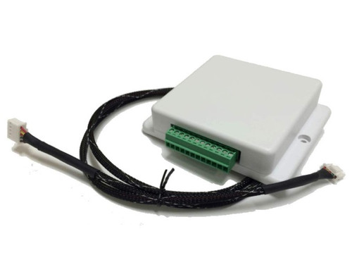
Supplied parts
Check that the box includes the following parts in addition to this installation manual:
- 1 x Thermostat Interface 2 (PAC-US445CN-1)
- 1 x PAA unit accessory cable
Safety precautions
- Thoroughly read the following safety precautions before use.
- Hazards that can occur from incorrect handling are classified by the symbols below:
WARNING Incorrect handling can result in death, serious injury, etc.
CAUTION Incorrect handling can result in bodily injury and/or structure damage. - After reading this manual, keep it for future reference. When the device is reinstalled or repaired, give this manual to those who provide these services.
When the user changes, make sure the new user receives this manual.
WARNING
- Only a dealer or qualified technician should install, relocate, reinstall or repair the device.
- Improper installation or repair may result in electrical shock or fire.
- Properly install the device on a stable, load-bearing surface.
Device installed on an unstable surface may fall and cause injury. - Only use the specified cables; securely connect each so that the terminals do not bear any cable weight.
- Improperly connected or short-circuited cables may produce heat and cause a fire.
- Do not make any modifications or alternations to the device.
Modifications or improper repair may result in electric shock or fire. Consult your dealer for repair. - All electrical work should be performed by an authorized electrician according to local regulations and instructions outlined in this manual.
Shorting the power supply circuit or improper installation may result in electrical shock or fire. - Properly install the device according to the instructions in this Installation/Instruction Manual.
Improper installation may result in electric shock or fire.
CAUTION
- Do not install the device in a location where a flammable gas leak may occur.
Gas may leak, collect around the device, ignite and/or explode. - Do not install the device in environments where large amounts of oil (including machine), subsidizing gas, or acidic, alkaline, chemical sprays are present.
These types of substances may damage internal parts, cause device performance to be reduced, and cause electrical shock. - Do not install the device in a bathroom, kitchen or any room where steam could form.
Condensation may develop and cause electrical shock, and/or the device to malfunction. - Use standard wires with the proper current capacity to avoid the possibility of a current leak, excessive heat, and/or fire.
- Do not touch the main circuit board; also, make sure dust does not accumulate on the circuit board.
- When installing the device in a hospital, communication facility, etc., provide sufficient protection against frequency noise.
Power generators and inverters, and high-frequency medical or radio communication equipment may interfere with the normal operation of this device. Subsequently, the device may also affect medical treatment, image broadcasting, etc., by creating frequency noise. - Include some slack in the power supply wires.
Tension on the wires may cause them to excessively heat up and/or break, resulting in a fire. - Do not install the device in a location where there is direct sunlight or where the temperature may become greater than 40° C (104° F) or less than 0° C (32° F).
If the device is installed in such place, it may result in deformation or malfunctions. - Do not immerse the device in water.
Doing so may lead to electric shock or malfunctions.
System configuration
WARNING
The thermostat should be configured for use with a conventional system (not heat pump).
| Thermostat Interface terminals | |
| Terminal | Purpose |
| TC | C: common (in) |
| C | C: common (out) |
| TR | R: 24 VAC (in) |
| R | R: 24 VAC (out) |
| G3 | High fan speed |
| G2 | Medium fan speed |
| G1 | Low fan speed |
| Y2 | Stage 2 cooling |
| Y1 | Stage 1 cooling |
| W2 | Stage 2 heating |
| W1 | Stage 1 heating |
| G | Fan |
- All wiring shown should be performed with 18 AWG thermostat wire.
- Terminals on the PAC-US445CN-1 support 20-30 VAC.
- High/medium/low fan signals are optional and may not be available on all thermostat models.
- W2 and Y2 signals are optional and may be omitted for single-stage thermostats.
- The PAC-US445CN-1 runs in two modes: heating/cooling or off/fan.
Upon receiving the initial request from the thermostat for the heating/cooling mode, the Thermostat Interface switches to the heating/cooling mode.
For indoor units that support Mode 25 and Mode 27 initial settings, the G signal at the time of entering the heating/cooling mode determines the fan state during thermal off. If the G signal was on, the thermal off fan is on. If the G signal was off, SW1-2 and SW 2-5 settings determine the thermal off-fan speed.
Once there is no longer a request from the thermostat for heating or cooling, the Thermostat Interface switches the indoor unit to either off or fan mode depending upon whether the G signal is off or on. If SW1-1 has enabled delay time, the unit remains in heating or cooling mode for 2 hours before switching to off or fan mode.
Example 1: Two-stage cooling and heating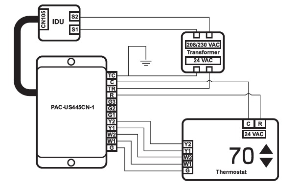
Example 2: Single-stage cooling and heating
Example 3: Single-stage cooling and heating with dedicated fan speed relays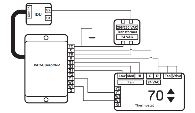
Example 4: Single-stage cooling with an alternate primary heating source
Note: For this configuration, it is recommended to set SW2-6 to the ON position.
Follow the wiring from Example 2 with the following adjustments:
- Connect thermostat W1 to the alternate heat source.
- Connect the thermostat W2 terminal to the PAC-US445CN-1 W1 terminal.
How to install
- Device configuration
Initial settings can be configured via the two banks of DIP switches on the circuit board, SW1, and SW2. The circuit board can be accessed by unfastening the four screws on the back of the case.
Note: Factory default is OFF for all switches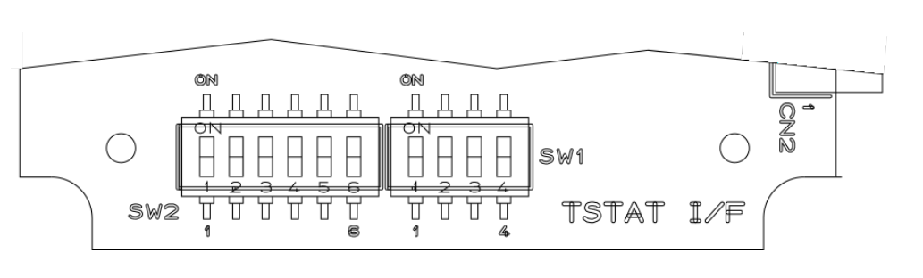
Functions of DIP switch
Zero delay timer
- SW1-1: Chooses the fan/off delay mode following the heating or cooling mode.
SW1-1 Delay timer OFF Stay in heating or cooling mode for 2 hours once W1 or Y1 is no longer active, which provides more efficient operation but does not respond to fan request changes (G) during the 2 hours. This setting allows more time for defrost timers in the outdoor unit to run (default). ON Once heat or cool request W1 or Y1 is no longer active, the system turns off or goes into fan mode immediately depending on the G signal. This is less efficient operation but responds more quickly to fan request changes. This setting operates most like the previous Thermostat Interface with zero hold time after achieving set point. - Fan speed during cooling thermal off if G is off
SW1-2: Chooses the cooling mode thermal off fan speed when G is not energized. This setting depends upon whether it is more important to stop the fan when not cooling or to keep the air moving when not cooling.SW1-2 Mode 27 / Fan speed OFF 2 (default) / Off ON 3 / Extra low - SW1-3/4: The indoor unit fan speed can be adjusted via the following settings:
SW1-3 SW1-4 Result OFF OFF Custom Auto (default) ON OFF Medium OFF ON High ON ON Auto Note: Custom Auto (default) provides higher fan speeds for more comfortable fan speed operation vs. the more efficient Auto.
Two-stage thermostat operation
SW2-6: Adjusts indoor unit operation during stage 1 heating (W1) and stage 1 cooling (Y1) according to the following table:SW2-6 Operation during stage 1 OFF The capacity is adjusted so that the room temperature is adjusted (heated or cooled) at a fixed rate (default). ON Full capacity Note: When either Y2 or W2 is left unconnected, it is recommended to set SW2-6 to the ON position. When both Y2 and W2 are connected, it is recommended to set SW2-6 to the OFF position.
Static pressure settings
SW2-1, SW2-2, SW2-3: Adjust the static pressure function settings of the indoor unit according to the following table:DIP switch position on PAC-US445CN-1 Indoor unit settings SW2-1 SW2-2 SW2-3 Mode 8 Mode 10 Mode 23 Mode 11 OFF OFF OFF Not set Not set Not set Not set OFF OFF ON Not set Not set Not set Not set OFF ON OFF 2 1 Set by SW2-4 2 OFF ON ON 2 2 Set by SW2-4 2 ON OFF OFF 1 1 Set by SW2-4 2 ON OFF ON 1 2 Set by SW2-4 2 ON ON OFF 3 1 Set by SW2-4 2 ON ON ON 3 2 Set by SW2-4 2 Refer to the appropriate indoor unit installation manual for Mode 8 and Mode 10 function setting definitions.
SW2-4: Adjusts Mode 23 function settings according to the following table:SW2-4 Mode 23 OFF 1 (default) ON 2 Refer to the appropriate indoor unit installation manual for Mode 23 function setting definitions. For Mode 23 function settings for the PAA unit, refer to the “Usage with PAA unit” section in this manual.
Fan speed during heating mode, thermal off
SW2-5: Adjusts Mode 25 initial setting according to the following table.This setting depends upon whether it is more important to stop the fan or to keep the air moving when not heating.SW2-5 Mode 25 / Fan speed OFF 2 (default) / Off ON 1 / Extra low Thermostat Interface non-changeable function settings
In addition, the thermostat interface also affects the following function settings of the connected indoor unit.Mode When using the thermostat interface Mode 1 (auto recovery after power failure) Always enabled Mode 2 (room temperature detection location) Unused (room temperature detected by the connected thermostat) Mode 24 (heat offset for height) Unused Additional function settings not addressed by the Thermostat Interface may be configured by temporarily connecting an MA remote controller. Indoor unit Mode settings only work for M-Series indoor units that begin with an “S” and P-Series units.
Installing the Thermostat Interface
Make sure power supply to the indoor unit is off. We also recommend configuring the DIP switch settings (see “Device configuration” section) before installing the Thermostat Interface.
- Choose a place to install the PAC-US445CN-1. The device provides two mounting holes that can be used to mechanically affix the case to a solid surface. Double-sided tape may be used to affix the device. When using tape, ensure the tape is approved for use within the anticipated operating temperature ranges.
Install the transformer, as necessary, per building code and manufacturer’s installation instructions. - Make sure the power supply to the indoor unit is off. Connect the PAC‑US445CN-1 cable to the connector CN105 on the indoor unit control board.
- Connect PAC-US445CN-1 terminals using 18 AWG wire.
Grouping
The connection of more than one PAC-US445CN-1 to a single set of thermostat dry contacts is not supported.
Temperature sensing
The PAC-US445CN-1 relies upon both the 24 VAC thermostat and the indoor unit’s thermistors in order to monitor room temperature. The thermostat’s temperature sensing is used to set the room temperature. The indoor unit thermistor is used when calculating cooling and heating rates of change.
Usage
Operate the third-party thermostat per the manufacturer’s instructions. During normal operation, the connection of Mitsubishi Electric remote controllers (e.g. MA/ME) is not supported as they will interfere with the correct operation of the PAC-US445CN-1.
Notes:
- The indoor unit will limit the internal temperature control set point based on the indoor unit specification.
- Fan signals G1,G2, and G3, when energized, take precedence over SW1-3 & 4.
- Only fan speeds available on the IDU can be set by the Thermostat Interface.
- When all cooling and heating signals are disabled and the 2-hour period (if enabled) has expired, energizing G will place the IDU into fan mode.
- When used with the PAA unit, it is recommended to set SW1-2 and SW2-5 to remain in default setting of OFF
Usage with PAA unit
The PAC-US445CN-1 Thermostat Interface 2 must be installed in the PAA unit control box if a third-party 24 VAC thermostat is used to control the PAA unit. Previous Thermostat Interface PAC-US444CN-1 is not compatible with the PAA unit.
How to install Thermostat Interface in PAA unit control box
Make sure power supply is off.
- Use M3‑0.5 x 12 mm metric socket cap head screws and 3 mm nuts, or equivalent (field supplied), to attach the Thermostat Interface 2 to the top of the protruding metal bracket in the control box (see image below). Ensure the Thermostat Interface is securely attached to the bracket.
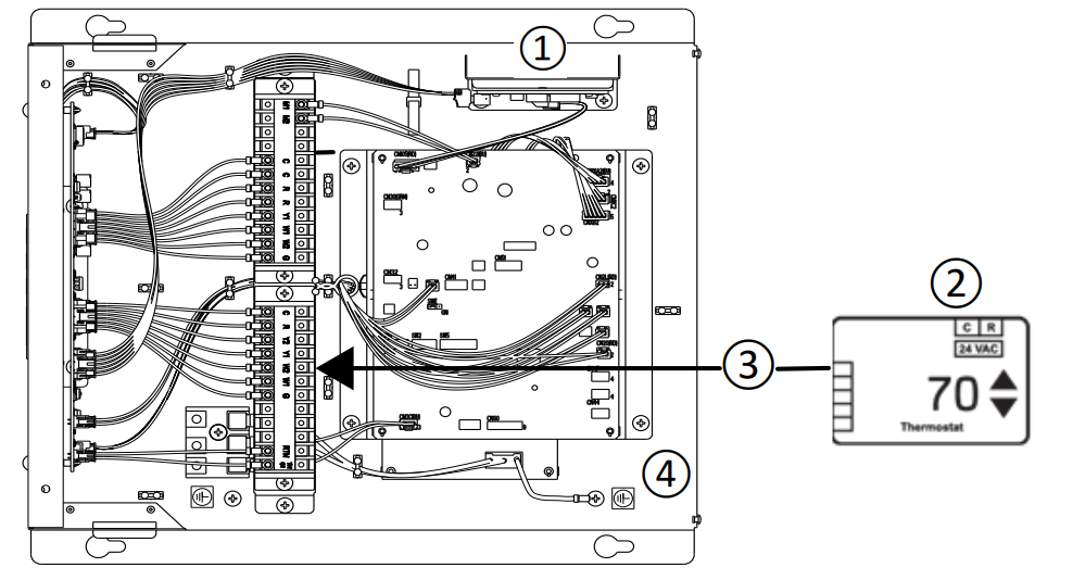
- Thermostat Interface
- Third-party thermostat
- Thermostat control signals
(R, C, W1, W2, Y1, Y2, G) - PAA unit control box
- Connect the Thermostat Interface to the CN105 connector on the control board.
- Connect the PAA unit accessory cable included with the PAC-US445CN-1 to the CNH02 connection on the relay board in the PAA control box.
- Connect the opposite end of the PAA unit accessory cable to the corresponding connections on the Thermostat Interface 2.
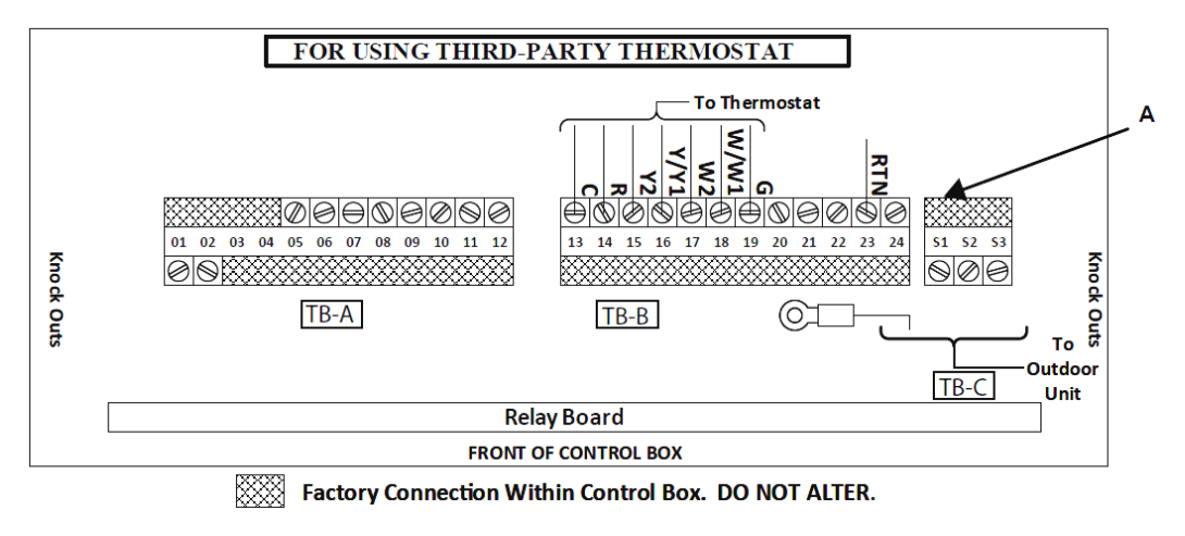
Cable assembly connections to the Thermostat Interface 2 Wire color Signal Green G: fan White W1: first stage of heating Brown W2: second stage of heating Yellow Y1: first stage of cooling Blue Y2: second stage of cooling Light blue C: 24 VAC return Red R: 24 VAC hot - Connect the thermostat to the pins/signals (13A to 19A) on the terminal block in the control box as shown in the following image.
DIP switch SW01 on the relay board is located as indicated in the image and has 4 switches that change the configuration.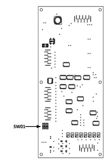
Thermostat power supply
The thermostat may receive power from the furnace transformer or may have a separate power supply. An example of when it might have it’s own power supply is when using a damper control system as dampers typically require more power than the furnace transformer can supply.
SW01-1: Determines whether to allow the thermostat to provide its own power or allow the furnace to supply power to the thermostat in Emergency and Normal operation modes according to the following table:
| SW01-1 | Result |
| OFF | Electronically disconnects the R line from the furnace to the auxiliary control equipment and allows the auxiliary equipment to provide its own power. |
| ON | Electronically routes the R line from the furnace through the PAA unit control box to the thermostat terminals if connections within the PAA unit control box provide operating power to the thermostat in Emergency and Normal operation modes (default). |
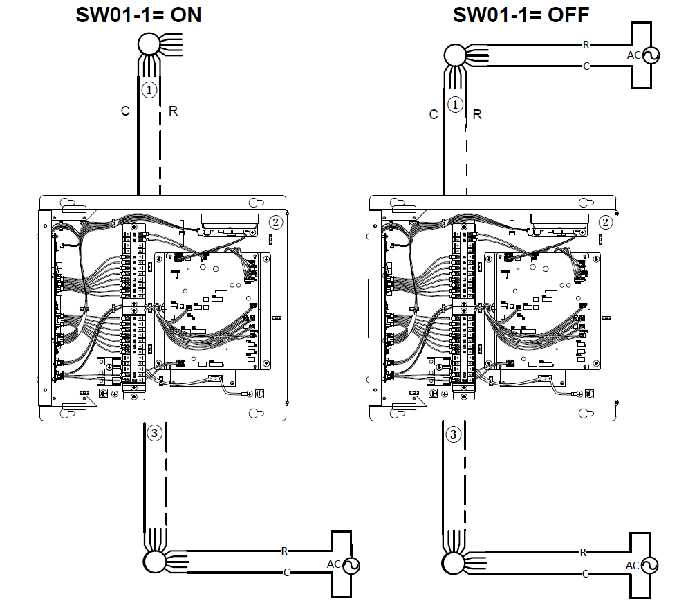
- Signals from thermostat
- PAA unit control box
- Control signals to the furnace (See terminal block image in “How to install
Thermostat Interface in PAA unit control box” section.)
SW01-4: Determines Emergency and Test mode operations according to the following table:
| SW01-4 | Result |
| OFF | Thermostat (or non-adjustable thermostat, if used) controls the heat and fan signals applied to the furnace during Emergency operation modes (default). |
| ON | Test mode operation |
For information about the non-adjustable thermostat and Test mode operation, refer to the PAA unit installation manual.
Thermostat Interface DIP switch settings for PAA unit only
SW2-4: Adjusts PAA unit Mode 23 function settings according to the following table.
Note: This DIP switch is on the Thermostat Interface, not the relay board of the PAA unit.
If the furnace does not support two fan speeds via Y1 and Y2, set Mode 23 to 1 for G and Y.
If the furnace supports two fan speeds via Y1 and Y2, to allow that to be used when cooling or heating using the heat pump, set Mode 23 to 2. For Mode 23 setting 2, the recommended DIP switch SW1-3/4 setting is Auto to vary fan speed, not Custom Auto.
| SW2-4 | Mode 23 |
| OFF | 1 (default) |
| ON | 2 |
Refer to the PAA unit Installation Manual for connections to the furnace based upon the setting of Mode 23.
After changing the Mode 23 setting, you need to power cycle the system for the change to reliably take effect
REFERENCE
Download Manual
MITSUBISHI ELECTRIC PAC-US445CN-1 Thermostat Installation Manual

MITSUBISHI ELECTRIC PAC-US445CN-1 Thermostat Installation Manual