
Lux TX1500U PROGRAMMABLE THERMOSTAT

IMPORTANT!
- Please read all of these instructions carefully before beginning installation.
- Label every wire terminal designation on your existing thermostat wiring before removing your old thermostat.
- Ignore the color of the wires since they may not comply with any standard. Please connect wires using the terminal letter designations.
PRODUCT OVERVIEW

SYSTEM COMPATIBILITY
The electrical rating for this thermostat is 1.5 Amps per terminal, with a maximum total combined load of 3.0A for all terminals combined.
COMPATIBLE WITH:
- Most 24-volt heating and cooling systems
- 1 or 2 stage Heat / 1 stage Cool: Gas, Oil or Electric systems
- 1 or 2 stage Heat / 1 stage Cool: Heat Pump systems
- 3-wire hydronic (hot water) zone valves
- Gas Millivolt heaters
NOT COMPATIBLE WITH:
- 120/240 VAC line-voltage systems (without a transformer), ask your LUX dealer for thermostats to control these systems.
FEATURES
- 1 or 2-Heat / 1-Cool, 7-day programming
- Universal Compatibility for all system types
- Each day of the week can be programmed separately
- Easy to use, touchscreen menu operation
- User-selectable periods per day (2 or 4)
- User-selectable programmable or non-programmable operation
- LuxLight® EL (Electro-Luminescent) lighted display
- Energy usage monitor
- Programmable air filter life timer
- Programmable keypad lockout for unauthorized users
- Manual temperature hold
- Adjustable vacation hold (1 to 30 days)
- Temporary temperature override
- Adjustable temperature differential / cycle-rate
- Adjustable 2nd heat stage Offset setting
- User temperature calibration
- Adjustable heat/cool set temperature limit stops
- Smart recovery
- Dual-powered (battery and/or 24-volt system powered)
- Battery-free memory storage
- F/C temperature display
- 12/24-hour clock display
- 5/2-minute selectable time delay for equipment protection
TOOLS YOU MAY NEED
- Screwdrivers
- Wire Stripper
- Wire Cutter
- Drill with assorted drill bits (new installations only)
MOUNTING LOCATION
On replacement installations, mount the new thermostat in place of the old one unless the conditions listed below suggest otherwise. On new installations, please follow these general guidelines:
- Mount the thermostat on an inside wall, about 5 ft. (1.5m) above the floor.
- Do not locate the thermostat where air circulation is poor such as in a corner, alcove, or behind a door that is normally left open.
- Do not locate the thermostat where unusual heating or cooling conditions may be present, such as: direct sunlight, above a lamp, television, or radiator, or on a wall next to an exterior door or window.
- Do not locate in a damp environment, as this can lead to corrosion that may shorten thermostat life.
- If painting or construction work is still ongoing, cover the thermostat completely or wait until this work is complete before installation.
WARNING:
All wiring must conform to the local codes and ordinances that are in your particular location.
REMOVE OLD THERMOSTAT

- Turn OFF the electricity to all heating and cooling components. Do not turn the electricity back on until all work is completed.
- Remove the front portion of your old thermostat to expose the wiring connections.
- Write down the letters printed near each wire terminal that is used, and also the color of each wire that is connected to it. Self-adhesive wire labels are also enclosed.
- Carefully remove the wires one at a time, and bend them in a manner so that they do not fall back inside the wall. Do not allow bare wire ends to touch each other.
- Loosen the mounting screws for the old thermostat and carefully remove it from the wall.
INSTALL THERMOSTAT BASE

- Strip wire insulation leaving only 3/8 in. (9.5mm) bare wire ends, and clean off any corrosion present.
- Fill the wall opening with non-combustible insulation to prevent drafts from affecting the thermostat’s normal operation.
- Route the wires through the opening in the new thermostat base plate, and hold the base against the wall. Try to line up the screw holes from the prior thermostat, and install the mounting screws.
- If the previous holes cannot be used, hold the thermostat base against the wall so that it appears straight and level (position the base for best appearance) and mark for the new screw holes. Attach the base to the wall using the screws provided (use the supplied plastic anchors if needed when mounting to a soft material such as drywall).
WIRING INFORMATION
CONNECTING THE WIRES
When attaching the wires to the thermostat, please ensure that the bare wire ends are held ALL the way into the terminal block while the screw is being tightened.
WIRING BASE PLATE NOTICE
This thermostat model is part of a family of similar models that have the same general visual appearance. Even though this base plate may look the same as base plates from other models, the wiring connections may have different terminal letters for different purposes. Please do not interchange the back plates and/or thermostat front halves of other similar-looking models. Doing so may cause undesired heating and/or cooling operation to occur.
(Important, please read all notes before connecting wires)
- If the information provided in the following wiring diagrams does not clearly represent or match your system, please refer to the “TECHNICAL ASSISTANCE” section of this manual, and contact us before removing any of your existing thermostat wiring.
- All of the dashed wires shown in the wiring diagrams are either optional, or their usage depends upon your specific system type or brand.
- For example Diagram #1 shows the fan wire as optional. If your system does not have a fan, than this terminal will not be used.
- Terminal letters shown in black represent typical wiring applications. Depending upon the brand of your specific system or thermostat, your terminal letters may not match exactly. Terminal letters shown in gray represent other possible wiring designations that you might see on your existing thermostat terminals.
- The optional “C” terminal is used for powering the thermostat by the 24- volt system, using the System Common wire. This can be used alone, or in addition to installing batteries as a backup.
NOTE: connecting the System Common wire to the thermostat is not necessary for heating and cooling to function properly. - If your old thermostat has both a “Y” and “C” wire present, then “C” is most likely a System Common wire.
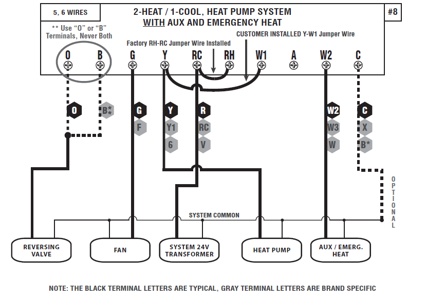
- for Heat Pump systems, you will use either the “O” terminal or the “B” terminal on this thermostat, but not both. If your old thermostat has both an “O” and a “B” wire present, then “B” is likely a System Common wire and may be connected to the “C” terminal. Connecting a System Common wire to this thermostat’s “B” terminal may damage the thermostat, and also your heating and cooling system.
- Some Heat Pump systems have a wire for AUX electric heat (usually W2), and also a separate wire for Emergency electric heat (usually E). This thermostat uses the W2 terminal for both AUX and Emergency Heat. Tape off your “E” wire, and confirm that all components function without it.
- If replacing an old thermostat that has a mechanical clock, there may be two wires labeled as “C” for the clock power. Tape off these wires and do not connect them to the “C” terminal of this thermostat.
WIRING DIAGRAMS:
DIAGRAM SYSTEM TYPE / DESCRIPTION PAGE #
- #1 CONVENTIONAL: HEATING ………………………………………8
1-STAGE OR 2-STAGE 2, 3, 4, 5 WIRES - #2 CONVENTIONAL: HEATING ………………………………………9
3-WIRE ZONE VALVE 3, 4 WIRES - #3 CONVENTIONAL: COOLING……………………………………..10
1-STAGE 3, 4 WIRES - #4 CONVENTIONAL: HEATING AND COOLING………………………11
1-STAGE HEAT 4, 5 WIRES - #5 CONVENTIONAL: HEATING AND COOLING………………………12
2-STAGE HEAT 5, 6 WIRES - #6 CONVENTIONAL: HEATING AND COOLING………………………13
TWO-TRANSFORMERS 5, 6 WIRES - #7 HEAT PUMP: HEATING AND COOLING………………………14
SINGLE-STAGE ONLY 4, 5 WIRES - #8 HEAT PUMP: HEATING AND COOLING………………………15
WITH AUX / EMERGENCY HEAT 5, 6 WIRES


HARDWARE SETUP OPTIONS
On the thermostat’s circuit board, there is a row of DIP switches, labeled #1 through #8. The position of these switches will change how the thermostat operates, and also how information is conveyed to you on the LCD display screen. If you make any changes to these options, the changes are not recognized unless you either: change the position of the HEAT/OFF/COOL mode switch, or press the “HW RST” (Hardware Reset) button on the circuit board. The use of this button is further described in the “ADVANCED FEATURES” section of this manual.
These option switches are very small and should be moved carefully using objects such as: an eyeglass screwdriver, fine-point pen, toothpick, or similar. The listing below describes the available choices for each option switch:

- SWITCH #1 (SYSTEM): [OFF/RIGHT = FURN, default] This setting is used for the majority of all heating systems that are not heat pumps. Examples for this setting would be: natural gas furnace, hot water baseboard heat, and oil heat. [ON/LEFT = HP] Use this setting if you have a heat pump unit (which looks just like an outside air conditioning unit, but is used for both cooling and heating).
- SWITCH #2 (TYPE): [OFF/RIGHT = PROG, default] The thermostat controls the room temperature by following temperature program periods that you set up based upon your daily routine. [ON/LEFT = MAN] The thermostat operates manually just like a mechanical or non-programmable model. This method of operation is very basic and only shows the room temperature and set temperature; there are no temperature programs, days of the week, or clock times.
- SWITCH #3 (PERIODS): [OFF/RIGHT = 4, default] The thermostat uses four temperature program periods in both heating and cooling (MORN, DAY, EVE, and NITE). Each period has a separate start time and a set temperature. [ON/LEFT = 2] The thermostat operates in the same manner as above, however, there are only two temperature program periods for heating and cooling (DAY and NITE). This may be more convenient if you are typically home during the day, and only need the set temperature to be different while you are sleeping.
- SWITCH #4 (SCALE): [OFF/RIGHT = F, default] All temperature values are displayed using the Fahrenheit scale. [ON/LEFT = C] This setting displays all temperature values using the Celsius scale.
- SWITCH #5 (TIME): [OFF/RIGHT = 12 HR, default] This setting displays the clock times and temperature program period start time values on the screen using US standard AM and PM values. [ON/LEFT = 24 HR] This setting displays the clock and temperature program period start time values on the screen using the 24 HR military-time format (17:30 hours, 22:00 hours, without using AM/PM).
- SWITCH #6 (DELAY): [OFF/RIGHT = 5 MIN, default] This sets the minimum length of time that Heat or Cool must remain either On or Off, before it will automatically switch to the On or Off state. This internal delay prevents rapid cycling of your system and provides equipment protection particularly for cooling units. The 5-minute setting is fine for most applications. [ON/LEFT = 2 MIN] If you feel that your system may need to cycle more frequently than the thermostat is allowing, then you may use the 2-minute setting.
- SWITCH #7 (RECOVERY): [OFF/RIGHT = DISABLE, default] The Early Recovery feature affects how the thermostat transitions from an energy-saving setback (DAY and NITE) program period to a comfort (MORN and EVE) program period temperature when it is following the daily temperature programs. When this is disabled, the thermostat makes a set temperature change at the beginning of an upcoming period’s start time. [ON/LEFT = ENABLE] The Early Recovery feature will calculate the capability of your system and turn on the heating or cooling early so that the temperature in your home reaches the desired set point as close as possible to the start of the period. During the time that the thermostat is performing a recovery, the words “IN RECOVERY” will be shown, alternating at the top of the display with the current system mode.
- SWITCH #8 (BATTERY MONITOR): [OFF/RIGHT = ON, default] This setting, regularly monitors the battery level and shows “LOW BAT” on the screen if the batteries need to be replaced. Use this setting at all times when batteries are present in the thermostat. [ON/LEFT = OFF] This setting only applies if you are NOT physically using batteries in the thermostat, and are powering the thermostat entirely from the system (“C” wire terminal).
GAS / ELEC SLIDE SWITCH (FAN OPERATION):

This switch is a physical component by itself on the circuit board and is much larger than the DIP switches listed above. [DOWN = GAS, default] This setting lets the heating system control the blower fan automatically by itself. Systems that would typically use the “GAS” setting would be: natural gas, propane, or oil furnaces. This setting has no effect on Cool mode operation. [UP = ELEC/HP] This setting runs the system’s blower fan when heat is called for, and is required for heating systems that do not control their own fan while the thermostat is in HEAT mode. Heat pump systems, and units with an electric heating element typically require this setting.
COMPLETE THE INSTALL
Once the hardware options are set, install two new Energizer® or DURACELL® “AA” size alkaline batteries. Ensure that the batteries are installed in the proper direction as per the markings shown in the battery tray. If the batteries were already installed before changing the hardware setup options, change the position of the HEAT/OFF/COOL System Mode switch to accept the new hardware option switch settings.
FRONT PANEL ITEMS
These two items below are both located on the right side of the thermostat housing.
HEAT / OFF / COOL, SYSTEM MODE SWITCH: Set this switch to HEAT to control your heating system, and COOL to control your cooling system. The OFF position will disable both the heating and cooling units.
AUTO / ON, FAN MODE SWITCH: When this switch is in AUTO, the blower fan (if present in your system) will automatically cycle on and off by itself while heating or cooling is running. When in the ON position, the blower fan will run constantly with or without a demand for heating or cooling, even when the System Mode switch is in the OFF position.
NOTE: The Fan Mode switch only works if your system provides a wire for the thermostat’s “G” wire terminal, to control a blower fan. The Fan Mode switch has no effect in systems that do not have a blower fan (such as a hot water radiator system).
OPERATING INSTRUCTIONS
TOUCHSCREEN MENU CONTENTS:
- SET DAY/TIME
- SET/REVIEW “HEAT/COOL” PROGRAMS (not present in OFF mode)
- SET/REVIEW FILTER USAGE
- rEVIEW “HEAT/COOL” ENERGY USAGE (not present in OFF mode)
- SET/REVIEW SWING VALUE
- SET KEYBOARD LOCK CODE (not present in OFF mode)
- SET “HEAT/COOL” TEMPERATURE STOP (not present in OFF mode)
- TEMPERATURE SETBACK (not present in OFF mode)
SET DAY AND TIME: Press the MENU button. The first menu item shown is “SET DAY/TIME”, press the OK button. With the day flashing, press UP or DOWN to set the day of the week. Press NEXT and the clock time will start flashing. Use UP or DOWN to set the time, making sure the AM/PM indication is correct. Holding the UP or DOWN buttons will make the clock digits scroll rapidly. Press the EXIT button to return to the Normal Run screen.
HEATING AND COOLING: Basic operation of your heating or cooling system can be obtained by choosing either HEAT or COOL on the System Mode switch. Touch the Set Temperature digits on the screen and they will begin to flash. While they are flashing, the UP and DOWN buttons will be shown also, which you can use to adjust the current Set Temperature. When the thermostat is first powered up, it will follow a default temperature routine that is preset from the factory (shown below), until the clock has been set.
| PERIOD | HEAT MODE | COOL MODE |
| MORN | 6:00 AM 70 °F (21 °C) | 6:00 AM 78 °F (26 °C) |
| DAY | 8:00 AM 62 °F (17 °C) | 8:00 AM 82 °F (28 °C) |
| EVE | 6:00 PM 70 °F (21 °C) | 6:00 PM 78 °F (26 °C) |
| NITE | 10:00 PM 62 °F (17 °C) | 10:00 PM 75 °F (24 °C) |
There are on-screen indicators to show you when the thermostat is calling for heating or cooling to occur. In the Heat mode switch position, a flame will be present on the screen. A steady flame means that the thermostat is not calling for your heating system to run, while a flashing flame means that your heating system should be currently running. In the Cool mode switch position, a snowflake will be present on the screen. A steady snowflake means that the thermostat is not calling for your cooling system to run, while a flashing snowflake means that your cooling system should be currently running.
- EMERGENCY HEAT: (Heat Pump Configuration Only). While in normal Heat mode, one single press of the EMER button will activate Emergency Heat mode. While in Emergency Heat, the top of the screen will change from “Heat Mode” to show “Emer Heat”. A single press of the EMER button again will end Emergency Heat, and return back to normal Heat mode. If a power loss occurs while in Emergency Heat mode, the thermostat will continue to remain in Emergency Heat mode even after the power comes back on. Emergency Heat mode will prevent the first stage of your heat pump system from turning on, and use only the “W2” heat terminal (Auxiliary Heat) as the primary heating source. This will not only prevent the heat pump from wasting energy if outdoor temperatures are too low to support efficient operation, but it could also prevent damage to the heat pump if outside temperatures are below the manufacturer’s recommendations. As every heat pump has different operating characteristics, you should refer to your heat pump literature to determine when to disable the heat pump and run it in Emergency Heat mode.
- LCD DISPLAY BACKLIGHT: The display screen is lighted to assist viewing at nighttime, or in locations with low light levels. A press of any area on the touch panel will light the display for approximately 10 seconds. Any screen presses that occur while the light is on will reset the 10-second timer, causing the screen to remain illuminated for an additional 10 seconds.
- TEMPERATURE OVERRIDE: While in the Normal Run screen, the set temperature can be temporarily changed by pressing the Set Temperature digits, then press the UP or DOWN buttons. The set temperature will return to the programmed value stored in memory when the start time of the next upcoming program period is reached (Morn, Day, Eve, Nite). While a Temporary Override is in effect, the words “HEAT OVRRIDE” or “COOL OVRRIDE” will be shown in the display screen. An Override may be cancelled by either pressing the HOLD button two times, or by moving the mode switch to OFF, pausing briefly, then switching back to the HEAT or COOL position. When in the Normal Run mode, the display should say either “HEAT MODE” or “COOL MODE”.
- MINIMUM RUN TIME: The thermostat has a default internal time delay of 5 minutes between load-on and load-off activations to prevent heating or cooling system damage, which can occur from very frequent cycling. If heating or cooling does not turn on right away with a manual change in set temperature, please wait at least 5 minutes and the system should resume normal operation.
- TEMPERATURE HOLD: A Temperature Hold is used for maintaining a fixed set temperature. Once a Hold is initiated, the thermostat will maintain the set temperature indefinitely. A Hold may be used for days, weeks, or even months at a time, as long as the thermostat has adequate power. To enter
- Hold mode: press the HOLD button one time and the words “HEAT HOLD” or “COOL HOLD” will appear in the display. To cancel a Hold, press the HOLD button one more time. If a mains power failure occurs during a Temperature Hold, the thermostat will continue to remain in Hold mode even after the power comes back on.
NOTE: If you plan to leave the thermostat in Hold mode for an extended duration (unattended), it is advisable to install new Energizer® or DURACELL® “AA” size alkaline batteries prior to leaving to ensure reliable operation of your heating and cooling system. - STATIC NOTICE: This thermostat is protected against normal static electric discharges, however, to minimize the risk of damaging the unit in extremely dry weather, please touch a grounded metal object before touching your thermostat.
ADVANCED FEATURES
TEMPERATURE SWING SETTING, OFFSET SETTING, AND TEMPERATURE CALIBRATION:
NOTE: The Swing setting, Offset setting, and Calibration settings need to be performed in a timely manner, as the thermostat will timeout and automatically exit these adjustment screens after approximately 10 seconds without a button press.
- SWING DESCRIPTION: A thermostat works by turning your heating or cooling system on and off whenever the room temperature varies from the desired set-point temperature. The amount of this variation is called the Swing. Generally your system should cycle on about 3 to 6 times per hour. A smaller swing number makes the system cycle more frequently, so the room temperature is more precise and constant. A larger swing number will make the system remain on for a longer duration each time and decreases the number of cycles per hour. There is only one Swing setting, and this determines the cut-in and cut-out points for both the first and second stages (if present), in both Heat mode and Cool mode. The swing setting range is between #1 and #9 (0.25°F to 2.25°F, in 0.25°F degree increments (or 0.14°C to 1.25°C, in 0.14°C degree increments for Celsius)). Swing number 1 is the default setting.
- OFFSET DESCRIPTION: This setting is shown as a number of degrees, and is similar in nature to the Swing however this only effects the operation of the second (auxiliary) heating stage, if present. The setting range for Offset is from 0°F to 9°F degrees (0°C to 5°C degrees). When set to 0 degrees, the second heating stage is completely disabled while in regular Heat mode (Emergency Heat mode will still function for heat pump configurations). The Offset value will determine the number of degrees from the set point that will be required for the second heating stage to turn on. This setting can be used to conserve energy in situations where the second heating stage is more costly to operate when compared to the first stage.

- TEMPERATURE CALIBRATION DESCRIPTION: The internal temperature sensor in this thermostat is accurately calibrated at the factory, and in most cases, alterations to this setting should not be needed. The Temperature Calibration feature allows you to manually offset the measured temperature by as much as plus or minus 5°F (3°C) degrees from its original value. This feature can be useful to match or synchronize this thermostat to another one or more, if multiple thermostats are used in the same home.
- TO CHANGE THE SWING, OFFSET, AND CALIBRATION: Press the MENU button, then press the SCROLL button until “SET/REVIEW SWING VALUE” is shown on the screen, then press the OK button. The words “ADJUST VALUE SWING” will appear at the top of the screen, along with a single flashing digit. Use the UP and DOWN buttons to change the number value from #1 to #9. Press the NEXT button to accept the Swing setting and proceed to the Offset setting. After the Swing value has been accepted, the words “ADJUST VALUE OFFSET” will appear at the top of the screen, along with a single flashing temperature digit. Use the UP and DOWN buttons to change the number value between 0°F and 9°F degrees (0°C to 5°C). The 0° (zero) degree setting will disable the 2nd heating stage while in regular Heat mode. Press the NEXT button to accept the Offset setting and proceed to the Calibration setting. After the Offset value has been accepted, the words “ADJUST VALUE CAL” will appear at the top of the screen, along with a single flashing temperature digit. Use the UP and DOWN buttons to change the number value between –5°F and +5°F (–3°C and +3°C). The 0° (zero) degree setting is the default value, and will not alter the displayed room temperature from the measured reading. Press the NEXT button to accept the Calibration setting and return back to the setting. You can keep pressing the NEXT button to review your three setting values, or press the EXIT button to return to the Normal Run screen.
- SETBACK FEATURE: The setback feature is similar to both a Temperature Override and a Temperature Hold, in that both are used to maintain a fixed set temperature instead of following a programmed daily routine. A Setback can be considered the same as a Temperature Override, which can last for a longer duration that you can adjust from 1-12 hours, or 1-30 days. By default, when a Setback is activated in Heat mode, the set temperature used will be 5F (3C) degrees lower than the current set temp. For Cool mode, the set temperature used will be 5F (3C) degrees higher than the current set temp.
NOTE: The Setback settings need to be performed in a timely manner, as the thermostat will timeout and automatically exit these adjustment screens after approximately 10 seconds without a button press. - TO START A SETBACK: Press the MENU button, then press the SCROLL button until “TEMPERATURE SETBACK” is shown, then press the OK button. The words “OVERRIDE LEFT” will appear at the top of the screen, along with two digits and the word “HRS”. Use the UP and DOWN buttons to set the duration for how long you would like to maintain a fixed set temperature (from 1 to 12 hours). If you would like to set the duration for longer than 12 hours, keep pressing the UP button. The display will change from “HRS” left to “DAYS” left, with an available duration of 1 to 30 days. Once you have selected your desired Setback duration, press the NEXT button to advance. The display will change from “OVERRIDE LEFT” left to “OVERRIDE TEMPERATURE”. Use the UP and DOWN buttons to select your desired Set Temperature that will be used during the Setback duration. Once complete, press the NEXT button to accept the setting and return to the Normal Run screen.
- TO CANCEL A SETBACK: A Setback can be cancelled by either pressing the HOLD button two times, or by moving the mode switch to OFF, pausing briefly, then switching back to the HEAT or COOL position. When in the Normal Run mode, the display should say either “HEAT MODE” or “COOL MODE”.
- TEMPERATURE LIMIT STOPS: There are two independent set temperature limit stops: a maximum heat set temperature, and a minimum cool set temperature. These stops do not prevent a user from performing normal actions like Temperature Override or Hold. The Heat Limit Stop prevents the set temperature from being adjusted higher than the heat limit setting. The Cool Limit Stop prevents the set temperature from being adjusted lower than the cool limit setting. Each of these temperature stops is user adjustable in one-degree increments, and these settings are protected by a selectable 2digit code to prevent unauthorized tampering. By default, this 2-digit code is “00”, and the temperature stops can be used as-is with this code.
NOTE: The Temperature Limit Stop settings need to be performed in a timely manner, as the thermostat will timeout and automatically exit the setting screens after approximately 10 seconds without a button press. The following examples are shown for setting the maximum set temperature for Heat mode. Setting the Temperature Limit Stop for Cool mode is done in the same exact manner with the System Mode switch in the Cool position, and instead you will be setting the minimum set temperature for cooling. Once a Temp Stop Lock Code has been selected, this same code is used for both Heat and Cool temp stops. - TO SET THE TEMPERATURE LIMIT STOP: Press the MENU button, then press the SCROLL button until “SET HEAT TEMP STOP” is shown, then press the OK button. The words “ENTER CODE” and “TEMP STOP” will appear at the top of the screen, along with two digits at the left. Use the UP and DOWN buttons to enter the current Temp Stop Lock Code (“00” by default). Press the NEXT button to advance. If the code entered does not match the current Temp Stop Lock Code, the words “WRONG CODE” will flash briefly, and you may try to enter the correct code again. If the current code has been entered correctly, you will have the ability to change the desired Temp Stop Lock Code to something else. The words “SET CODE” and “TEMP STOP” will appear at the top of the screen, along with two digits at the left. Use the UP and DOWN buttons to enter the desired Temp Stop Lock Code to be used, and press the NEXT button to advance. The words “SET HEAT RANGE STOP” will appear at the top of the screen, along with two large temperature digits in the middle. Use the UP and DOWN buttons to adjust the desired maximum heat set temperature value (or minimum set temperature value for Cool mode). Once complete, press the NEXT button to accept the setting and return to the Normal Run screen. IF YOU FORGET YOUR TEMPERATURE STOP LOCK CODE: The code can be reset to the factory default “00” by performing the following steps. Start with the System Mode switch in either the Heat or Cool positions, then change to the OFF position. Press and hold the HOLD, NEXT, and OK buttons all at the same time for at least 10 seconds. The screen will briefly show “00” on the screen to confirm that the Temp Stop Lock Code has been successfully reset to the factory default of “00”.
- KEYPAD LOCKOUT: You can lock the touch-panel buttons to prevent unauthorized tampering of your thermostat settings.
NOTE: These keypad lock instructions need to be performed in a timely manner, as the thermostat will timeout and automatically exit the keypad lock screens and return to the Normal Run screen after approximately 10 seconds without a button press. - TO LOCK THE KEYPAD: The System Mode switch must be in either the Heat or Cool position. Press the MENU button, then press the SCROLL button until “SET KEYBOARD LOCK CODE” is shown, then press the OK button. The words “ENTER CODE” will appear at the top of the screen, along with four digits at the left. Select a 4-digit code that you would like to use for locking the thermostat. Press the UP and DOWN buttons to change each digit individually, using the NEXT button to cycle through which digit is selected. Pressing the OK button will lock the thermostat touch panel using the 4-digit code that is shown on the screen, and return to the Normal Run screen with a padlock shown to confirm that the thermostat is now locked.
- TO UNLOCK THE KEYPAD: Press the padlock icon, and the words “UNLOCK KEYBOARD?” will appear at the top of the screen. Press OK to proceed with entering the unlock code (or press the EXIT button to cancel). The words “ENTER CODE” will appear at the top of the screen, along with four digits at the left. You will need to enter the proper unlock code that was used for initially locking the thermostat. Press the UP and DOWN buttons to change each digit individually, using the NEXT button to cycle through which digit is selected. With the correct lock code entered on the screen, pressing the OK button will unlock the thermostat. If the code entered does not match the current keypad lock code, the words “WRONG CODE” will flash briefly, and you may try to enter the correct code again.
- IF YOU FORGET YOUR KEYPAD LOCK CODE: The following steps can regain access to the thermostat. Remove the front portion of the thermostat from the wall, and briefly press the “HW RST” HARDWARE RESET button on the thermostat circuit board. More information about the use of this button is described later in this section.
- AIR FILTER MONITOR: In most systems that use a blower fan and air ducts, there is an air filter that is either replaceable or requires cleaning. The filter is usually located in the air handler, where the blower fan is. This thermostat feature assists you with keeping track of proper maintenance and/or periodic replacement intervals for your system’s filter. The Air Filter Monitor counts the duration of filter usage that has occurred, since the last time the Filter Monitor has been reset. This feature is for information purposes only, and does not affect the operation of your heating or cooling equipment, or the thermostat. When the filter usage duration has expired, the words “CHANGE FILTER” will appear at the top of the display screen, alternating with the current DAY and PERIOD.
- TO ACCESS FILTER INFORMATION: Press the MENU button, then press the SCROLL button until “SET/REVIEW FILTER USAGE” is shown, then press the OK button. The words “FILTER USAGE COUNT” will appear at the top of the screen, along with the total number of hours that have elapsed since the last time the filter counter was reset. Press the NEXT button to advance. The words “FILTER USAGE RESET?” will appear at the top of the screen. To reset the filter counter to the start of the current limit setting press the OK button. Press the NEXT button to advance.
The words “ADJUST VALUE FILTER LIMIT” will appear at the top of the screen. This shows the current setting value for how many filter run time hours can elapse before showing “CHANGE FILTER” in the Normal Run screen. The adjustment range for this setting is from 0 hours to 2000 hours, with 720 hours as the default. A filter limit setting of 0 (zero) hours will disable the filter monitor feature. Once complete, press the EXIT button to save all settings and return to the Normal Run screen.
NOTE: Air filters are sold based upon how many days they are rated for. One day of filter run time is actually considered only 8 hours (not a full 24, since your heating and/or cooling system only runs for approximately one-third of the time). For a “90-day” filter, use a limit setting of 720 hours should be used, and for a “30-day” filter, a limit setting of 240 should be used. - ENERGY USAGE MONITOR: Your thermostat contains a timer, which records the amount of “on-time” for your heating and cooling systems. There are three records that can be displayed for both Heat and Cool modes:
- The amount of system run time so far for today.
- The amount of system run time for yesterday.
- The total cumulative system run time since the timer was reset.
The Heat Energy Usage information is shown while the System Mode switch is in the Heat position, and the Cool Energy Usage information is shown while the System Mode switch is in the Cool position. The following examples are shown for viewing the Energy Usage while in Heat mode.
Viewing the Cool mode information is done in the same exact manner in Cool mode.
- TO VIEW THE ENERGY USAGE TIMERS: Press the MENU button, then press the SCROLL button until “REVIEW HEAT ENERGY USAGE” is shown, then press the OK button. The words “TODAYS ENERGY USAGE” will appear at the top of the screen, along with the amount of heating system runtime (displayed as “HH: MM”, for hours and minutes). Use the NEXT button to cycle between Today’s Usage, Yesterday’s Usage, and the Total Cumulative Usage for heat mode.
NOTE: For the Total Cumulative Usage, the timer will record up to a maximum of 99 hours and 59 minutes, then the display will change to “HHHH” for hours only, without the colon in the center. Pressing NEXT after the Total Cumulative Usage will show the words “TOTAL USAGE RESET?” at the top of the screen. Pressing OK at this screen will clear the Heat Energy Usage timer, and start back at 0 (zero). Press the EXIT button to return to the Normal Run screen. - HARDWARE RESET: The Hardware Reset button (labeled “HW RST”) is a small round push button that is located towards the right side of the circuit board, just below the battery holder. Pressing this button will cause the LCD display screen to become fully populated, the heating and cooling load relays to cycle off, read the position of the Hardware Setup Option switches, and will perform an internal system check of the thermostat components. If your thermostat appears to be acting in an erratic manner, pressing the Hardware Reset button may remedy this behavior. The temperature programs are not erased when a hardware reset is performed, however, the clock will have to be changed to match the current day and time.

- SOFTWARE RESET: The Software Reset button (labeled “SW RST”) is a small round push button that is located towards the right side of the circuit board, just below the battery holder. A Software Reset is used to erase all heating and cooling temperature programs, and any user-adjustable software values such as: Swing, Offset, and Calibration, to their original factory default values. To perform a Software Reset, press and hold the Software Reset button for at least 5 seconds. The LCD display screen will become fully populated, then return to normal. The thermostat will still retain the current day and time even after a Software Reset has been performed.

- COMPRESSOR PROTECTION BYPASS: This optional feature permits the installer or service technician to temporarily disable the built-in compressor protection delays. This is most useful for diagnosing and testing the heating and cooling systems after installation is complete, and should not be used during normal operation. To activate this feature, start with the System Mode switch in either the Heat or Cool positions, then change to the OFF position. Press and hold the OK button for at least 5 second. The thermostat will give a single beep sound to confirm that this feature has been activated. All compressor protection delays (in all modes of operation) will be disabled for 5 minutes. After the 5-minute duration has expired, the thermostat will return to normal operation automatically.
BATTERY REPLACEMENT
This thermostat is powered by two “AA” Alkaline batteries. The batteries should be replaced AT LEAST once per year to ensure reliable operation (or sooner, if the “LO-BATTERY” icon appears at the bottom of the display screen). The batteries are located on the back of the thermostat, at the top of the circuit board. The front portion of the thermostat can be removed from the back half by pulling straight outwards on the top and bottom of the thermostat housing, at the large indentations that are present in the center of the top and bottom edges. When installing new batteries, we recommend using only brand new Energizer® or DURACELL®, “AA” size alkaline batteries. Please observe the polarity markings shown in the battery compartment to ensure proper installation. When finished, line up the of thermostat to the base, and firmly press together to securely latch the front and back halves together properly.
TECHNICAL ASSISTANCE
If you have any problems installing or using this thermostat, please carefully and thoroughly review the instruction manual. If you require assistance, please contact our Technical Assistance department at 856-234-8803 during regular business hours between 8:00AM and 4:30PM Eastern Standard Time, Monday through Friday. You can also receive technical assistance online anytime day or night at http://www.luxproducts.com. Our website offers you troubleshooting guides, and answers to the most common technical questions, and also permits you to email your questions to our technical support staff at your convenience.
LIMITED WARRANTY
If this unit fails because of defects in materials or workmanship within three years of the date of original purchase, LUX will, at its option, repair or replace it. This warranty does not cover damage by accident, misuse, or failure to follow installation instructions. Implied warranties are limited in duration to three years from the date of the original purchase. Some states do not allow limitations on how long an implied warranty lasts, so the above limitation may not apply to you. Please return malfunctioning or defective units to the location from which the purchase was made, along with proof of purchase. Please refer to “TECHNICAL ASSISTANCE” before returning the thermostat. Purchaser assumes all risks and liability for incidental and consequential damage resulting from the installation and use of this unit. Some states do not allow the exclusion of incidental or consequential damages, so the above exclusion may not apply to you. This warranty gives you specific legal rights and you may also have other rights, which vary from state to state. Applicable in the U.S.A. and Canada only.
MERCURY WARNING AND RECYCLING NOTICE
Mercury is considered to be a hazardous material. If this product is replacing a thermostat that contains mercury in a sealed tube, contact your local waste management authority for instructions regarding recycling and proper disposal. It may be unlawful in your state to place it in the trash.
Philadelphia, PA 19112
www.luxproducts.com
856-234-7905
REFERENCE:
Download Manual: Lux TX1500U PROGRAMMABLE THERMOSTAT INSTALLATION AND OPERATING INSTRUCTIONS
Lux TX1500U PROGRAMMABLE THERMOSTAT INSTALLATION AND OPERATING INSTRUCTIONS