Lennox CS7500 Color Touchscreen Programmable Thermostat

Shipping and Packing List
- ComfortSense® 7500 , 7-day programmable touchscreen thermostat with back plate
- Mounting screws (M3.5x25mm self-tapping screws)
- 2 – Wall anchors
- 1 – Wall plate
- 1 – Warranty certificate
- 1 each – Homeowner and Installer Guides
NOTE – This thermostat is equipped with automatic compressor protection to prevent potential damage due to short cycling or extended power outages. The short-cycle protection provides a 5-minute delay between heating or cooling cycles to prevent the compressor from being damaged.
Overview
Description
The ComfortSense® 7500 thermostat is an electronic 7-day universal multi‐stage programmable touch screen thermostat. It also offers enhanced capabilities which include:
- humidification measurement and control,
- dew point adjustment control,
- dehumidification measurement and control,
- Humiditrol® Enhanced Dehumidification
Accessory (EDA) capability, - equipment maintenance reminders,
- worry-free memory storage feature,
- menu-driven touch-screen display.
This thermostat supports heat pump or non-heat pump units, with up to two stage heat pump and two auxiliary stages or two stages of heating and two stages of cooling.
Dimensions (H x W x D)
Case dimensions: 3-5/16 x 4-5/16 x 7/8 in. (84 x 110 x 22mm)
Wall Plate Dimensions (H x W)
Plate dimensions: 4-1/2” x 5-3/4” (114 x 146mm)
Compressor Short-Cycle Protection
A 5-minute compressor short-cycle protection timer begins when a compressor output is de-energized. Also, if a power loss occurs, the system will go into compressor protection mode and display “waiting” next to either a snow flake icon (compressor cooling), or flame icon (compressor heating) in the display.
Outdoor Sensor (Optional)
IMPORTANT
The outdoor sensor must be connected to operate a system with a Humiditrol® accessory.
An optional (purchase separately) outdoor sensor (X2658) is required for dual-fuel applications, outdoor temperature display on the home screen, balance points, dew point humidity control, and with Humiditrol® EDA.
In addition to measuring and displaying outdoor temperature, the outdoor sensor provides dew point adjustment and control for all models. If used with this thermostat, the sensor enables optimal heating equipment operation via programmable balance points.
NOTE – For proper operation of Humiditrol® EDA applications, the outdoor sensor (X2658) MUST be installed.
Refer to page 11 for remote sensor installation and thermostat setting configuration.

IMPORTANT
In all applications, the ComfortSense® Model 7500 thermostat can only be used with all residential units and approved commercial split‐system matches, and those which meet the following installation criteria:
- the installation uses 18 GAUGE thermostat wires or larger,
- thermostat wire run length DOES NOT EXCEED 300′ (91m),
- load from any thermostat connection is 1 AMP or LESS.
WARNING
Improper installation, adjustment, alteration, service or maintenance can cause property damage, personal injury or loss of life.
Installation and service must be performed by a licensed professional HVAC installer (or equivalent) or service agency.
CAUTION
This is a 24VAC low-voltage thermostat. Do not install on voltages higher than 30VAC.
Do not short (jumper) across terminals on the gas valve or at the system control to test installation.
This will damage the thermostat and void the warranty.
WARNING
Always turn off power at the main power source by switching the circuit breaker to the OFF position before installing or removing this thermostat. All wiring must conform to local and national building and electrical codes and ordinances.
Installation
Before beginning installation, note the type of equipment, number of stages, and any accessories being installed. This thermostat is a
24VAC low-voltage thermostat and requires a common wire to the thermostat to operate.
DO
- Shut off all power to system before installing.
- Read this entire document, noting which instructions pertain to your equipment and system requirements.
- Make sure that all wiring conforms to local and national building and electrical codes and ordinances.
- Use thermostat wire between the thermostat and the optional outdoor temperature sensor (may be separate wire pair or two wires of a multi-wire cable).
- Ensure load from any thermostat connection is less than 1 AMP.
DO NOT
- Install on voltages higher than 30VAC.
- Short (jumper) across terminals on the gas valve or at the system control to test installation. This will damage the thermostat and void the warranty.
- Install on outside walls or in direct sunlight.
- Exceed thermostat wire run length greater than 300 feet (91m).
INSTALLING THERMOSTAT
- Unpacked the thermostat and open the case with a thin-blade screwdriver. Place between wall base and unit and twist to separate unit from base.
- Select a location for the thermostat about 5 feet (1.5m) above the floor in an area with good air circulation at average temperature.
- Do not install the thermostat where it can be affected by:
- Drafts or dead spots behind doors and in corners.
- Not close to entrance or automatic doors
- Not close to heat generating equipment such as kitchen equipment
- Not in an enclose environment unless a remote indoor sensor is used.
- Hot or cold air from ducts.
- Radiant heat from sun or appliances.
- Concealed pipes and chimneys.
- Non-heated (non-cooled) areas such as an outside wall behind the thermostat.

- Use steps A through J (step J applicable when using provided wall plate) to install the thermostat.


WIRING THERMOSTAT
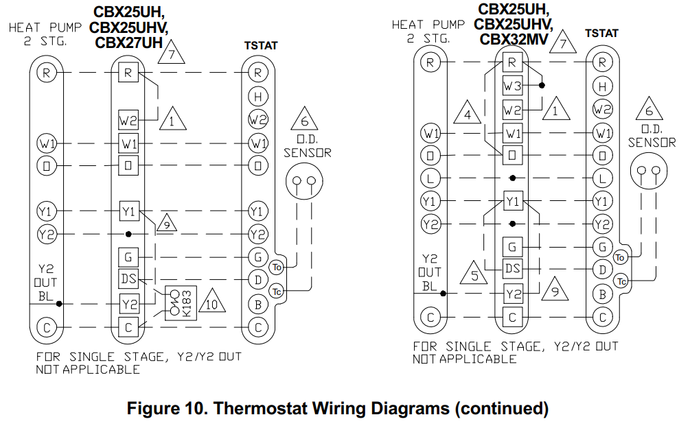
Thermostat wiring connections with various units, including dual fuel, zone control, and applications that include the Humiditrol® Enhanced Dehumidification Accessory (EDA). See figures 3 through 7. For whole home dehumidifiers, refer to the installation instruction for the dehumidifier.
- Connect wiring between thermostat, indoor unit, and outdoor unit as shown in the appropriate wiring diagram.
- Connect optional (purchase separately) outdoor sensor. See Installing Outdoor Sensor for further details and provided wiring diagrams.
- Seal the hole in the wall with a suitable material to prevent drafts from entering the thermostat case.
- Configure thermostat and equipment for system type, program the thermostat, and test system.
TERMINAL DESIGNATIONS
- Tc – Outdoor Temp. Sensor Connection 1
- To – Outdoor Temp. Sensor Connection 2
- H – Humidification relay (to Humidifier)
- D – Dehumidification relay (to DS terminal)
- W2 – Second-stage heating (non-heat pump) or 4th stage (heat pump)
- Y2 – Second-stage heating or cooling
- O – Cool active reversing valve
- B – Heat active reversing valve
- C – Common 24VAC
- G – Fan relay
- W1 – First-stage heating (non-heat pump or emergency heat) or third-stage heating (heat pump)
- Y1 – First-stage heating or cooling
- R – 24VAC power
Installing and Displaying Outdoor Temperature on Home Screen
Install the optional (purchase separately) outdoor sensor (X2658) on a northern wall of the home, away from direct sunlight or other heat sources that may affect its sensitivity.
NOTE – The outdoor sensor uses standard thermostat wiring; it may be wired using two wires of a multi-wire cable with a wire run not to exceed 300 feet or 100 meters.
- Connect outdoor sensor to terminals Tc and To on thermostat.
- To enable the outdoor sensor go to menu and touch settings and hold until the installer settings pop-up window appears.
- Touch confirm to proceed.
- From the installer settings menu, select outdoor sensor and select yes. A green check mark will appear next to the selection that confirms selection.
- To display the outdoor temperature sensor information on the home screen, from the home screen go to menu and touch settings. This will take you to the user setting screen. Select display and select outdoor temperature display and then select sensor.
NOTE – If the outdoor sensor is connected to the thermostat after the above procedure is completed and error code 9 appears on the screen, check your wiring connections to terminals TO and TC on the thermostat.


System Settings

- Touch menu option from the home screen.
- Touch and hold the settings option on the menu. This will display the installer settings notice and then menu. You may be asked for an access code. The factory default access code is 864.

SYSTEM SETUP
Sets the thermostat for operation with either a non-heat pump or heat pump and defines the number of compressor stages. Indoor unit settings include no heat, gas/oil or electric and number of indoor heat stages.
OUTDOOR SENSOR
Options are yes or no (default).
RESIDUAL COOL
Default is 0 seconds. This is the time, in seconds, that the fan runs after a call for cooling is satisfied in order to deliver any residual cooling ability from the coil and ductwork into the conditioned space. Options are 0, 30, 60, 90 and 120 seconds. Touch < to return to previous menu.
LOW AND HIGH BALANCE POINTS
These balance points are for heat pump systems only with an outdoor sensor installed and enabled plus an indoor unit setting enable. Either gas/oil or electric will enable the balance point options in the installer settings list.
- When in heat mode and the outdoor temperature is below the programmed Low Balance Point, then heat pump heating is not allowed and only backup heat will be used.
- When in heat mode and the outdoor temperature is above the programmed High Balance Point, then heat pump heating is allowed and backup heat will not be used.
- When in heat mode and the outdoor temperature is between the programmed Low and High Balance Points, then heat pump heating and backup heat can be used.
- Options are enabled or disable. The default for both is disabled. Once enabled, the following settings are available.
- The low Balance Point Default is 25°F.
Adjustable range is -40°F to 48°F. - The high Balance Point Default is 50°F.
The adjustable range is -38°F to 75°F.
NOTE – The high balance point minimum range is adjustable to within +2°F of the low balance point setting. For example, if the low balance point is set to 0°F, then the lowest setting for the high balance point is 2°F.
DEADBAND
The default is 2°F. The Deadband setting is the minimum difference between the cooling and heating set points. This setting is used in cool/heat mode to ensure smooth equipment operation. The deadband is adjustable from 2 to 9°F. Use the + or – option to select desired deadband. Touch < to return to the previous menu.
SMOOTH SET RECOVERY(SSR)
Options are enable or disable. Default is enable. When enabled, smooth set recovery begins recovery up to two hours before the programmed time so that the programmed temperature is reached at the corresponding programmed event time. Assume 12°F per hour for first stage gas/electric heating and 6°F per hour for first stage compressor based heating or cooling. With Smooth Set Recovery disabled, the control will start a recovery at the programmed time.
NOTE – Smooth Set Recovery and Stage2 Lock Out operations vary depending on equipment (see table 1).
SSR STAGE 2 LOCK OUT
Default is 20 minutes. Use the + or – option to set the number of minutes before the programmed event time that stage 2 is allowed to operate (20 to 120 minutes in 10 minute increments). Touch < to return to previous menu. This setting is ignored when SSR is disabled.
DEALER INFORMATION
This allows the installer to add dealer name, address, phone, email, website and number. Touch < to return to previous menu.
TEMPERATURE OFFSET
Default is 0°F. This setting can be used to offset the displayed space temperature by up to +/- 5°F. This offset also applies to the control temperature. Touch < to return to previous menu.
HUMIDITY OFFSET
Default is 0%. This can be used to offset the displayed and controlled space relative humidity (RH) by up to +/- 10% RH. Touch < to return to previous menu.
Table 1. Smooth Set Recovery (SSR) & SSR Stg 2 Lock Out Operation
|
Equipment Available |
When SSR is enabled then SSR Stage 2 lock out is enabled. Can be set between 20 and 120 minutes. Default is 20 minutes |
When SSR is disabled then SSR Stg 2 lock-out setting is disabled. |
| • Run heat pump (Y1) only | ||
| Single-stage heat pump with one or two stages of electric backup | • All backup heat (W1/W2) is enabled and SSR Stage 2 Lock Out is set between 20 – 120 minutes before the wake-up set point. | Run heat pump (Y1) and will have available backup heat (W1/W2) as needed. |
| • Run heat pump (Y1/Y2) only. | ||
| Two-stage heat pump with one- or two-stages of electric backup | • All backup heat (W1/W2) is enabled and SSR Stage 2 Lock Out is set between 20 – 120 minutes before the wake-up set point. | Run heat pump (Y1/Y2) and will have available backup heat (W1/W2) as need ed. |
|
Single-stage heat pump with single-stage gas or oil backup |
• Run heat pump (Y1) only • All backup heat (W1) is en abled and SSR Stage 2 Lock Out is set between 20 – 120 minutes before the wake-up set point. |
• Run heat pump (Y1) until a second- stage heating demand is needed which is determined by the time / temperature differential.
• Heat pump operation will stop and gas or oil heat will start. • Changeover and lock-in to W1 heat will occur until set point reached. |
|
Equipment Available |
When SSR is enabled then SSR Stg 2 lock out is automatically enabled. | When SSR is disabled then SSR Stg 2 lock-out setting is disabled. |
|
Single-stage heat pump with: • Two-stages of gas or oil backup • Modulation furnace |
• Run heat pump (Y1) only • All backup heat (W1/W2) is enabled and SSR Stage 2 Lock Out is set between 20 – 120 minutes before the wake-up set point. |
• Run heat pump (Y1) until a second- stage heating demand is needed which is determined by the time / temperature differential.
• Heat pump operation will stop and changeover to W1/W2 heat as need ed • Lock-in W1/W2 heat until set point is reached. |
|
Two-stage heat pump with one stage gas/oil backup |
• Run heat pump (Y1/Y2) only. • All backup heat (W1/W2) is enabled and SSR Stage 2 Lock Out is set between 20 – 120 minutes before the wake-up set point. |
• Run heat pump (Y1/Y2) until a second-stage demand is needed which is determined by the time / temperature differential.
• Heat pump operation will stop and gas or oil heat will start. • Changeover and lock-in to W1 heat will occur until set point is reached |
|
Equipment Available |
When SSR is enabled then SSR Stg 2 lock out is automatically enabled. | When SSR is disabled then SSR Stg 2 lock-out setting is disabled. |
|
Two-stage heat pump with: • Two-stages of gas or oil backup • Modulation furnace |
• Run heat pump (Y1/Y2).
• All backup heat (W1/W2) is enabled and SSR Stage 2 Lock Out is set between 20 – 120 minutes before the wake-up set point. |
• Run HP (Y1/Y2) until a second-stage demand is needed which is deter mined by the time / temperature dif ferential.
• Heat pump operation will stop and changeover and lock-in to W1/W2 heat until set point is reached. |
| Two stages of gas/oil heat or modulation furnace | Run W1 only; W2 is enabled and SSR Stage 2 Lock Out is set be tween 20 – 120 minutes before the wake-up set point. |
Run W1 heat and bring on W2 heat until set point is reached. |
| Single stage cooling | Run Y1 to wake up set point. | Run Y1 heat until set point is reached. |
| Single stage cooling | Run Y1 during recovery and en able Y2 field wake up set point. | Run Y1 and Y2 heat as needed until set point is reached. |
STAGE DELAY TIMER
Default is ON. When ON, all stage delay timers (stages 2, 3, and 4) are enabled and will serve to bring on additional stage(s) of cooling or heating on a timed basis (default 20 minutes) in cases when the previous stage of heating or cooling will not raise or lower the room temperature to the set point in a given time.
When OFF is selected all stage delay timers are disabled. This means stages are changed based on the temperature and not their timer delays. Scroll to STG DELAY TIMERS; and touch to select the applicable stage delay timer. Touch < to return to previous menu.
STAGE DELAY DIFFERENTIALS
Stage delays and differentials are individual set in the installer settings screen.
- STAGE 1 DIFF
Stage 1 differential is used in all thermostats. The default is 1.0°F but can be programmed between 0.5° and 8.0°F in 0.5°F increments. Touch < to return to previous menu. - STAGE 2 THROUGH 4 DIFF
(Where applicable) The default is 1.0°F but can be programmed between 0.5° and 8.0°F in 0.5°F increments. Touch < to return to previous menu. - STAGE 2 THROUGH 4 DELAY
(Where applicable) If STAGE DELAY TIMERS is turned ON, the default delay is 20 minutes but can be programmed from 5 to 120 minutes in 5-minute increments. If first stage fails to advance the ambient temperature toward the setpoint by 1.0°F in the programmed delay time, then the second stage is activated.
Scroll to STAGE 2 DELAY (or 3 or 4); Touch to select. Select the desired delay. Touch < to return to previous menu. - H/C STAGES LOCKED IN
Default is enabled. When set to disabled heat/cool stages are turned off separately). If set to enabled, heat/cool stages are turned off together. Touch < to return to previous menu. - STAGE 2 HP LOCK TEMP
Default is off (heat pump stage 2 operates normally). Use this setting in dual fuel applications to lock in the 2nd stage compressor when the outdoor temperature is at or less than the LOCK TEMP set point. Scroll to STAGE 2 HP LOCK TEMP; touch ENTER. Use – + option to select a LOCK TEMP between -40 and 75ºF. Touch < to return to previous menu.
| Configuration | Figures |
| Multi-stage Cooling for Heat Pump/Non-Heat Pump | 14 |
| Heating – Non-Heat Pump (1 or 2 stages) | 15 |
| Heating – Heat Pump with NO backup heat | 10 |
| Heating – Heat Pump w/electric heat (2-stage: 1compr/1backup) | 10 |
| Heating – Heat Pump w/electric heat (3 stage: 2compr/1backup) | 11 |
| Heating – Heat Pump w/electric heat (3 stage: 1compr/2backup) | 11 |
| Heating – Heat Pump w/electric heat (4 stage: 2compr/2backup) | 12 |
| Heating – dual fuel (2-stage: 1compr/1backup) | 13 |
| Heating – dual fuel (3 stage: 1compr/2backup) | 14 |
| Heating – dual fuel (3 stage: 2compr/1backup) | 15 |
| Heating – dual fuel (4 stage: 2compr/2backup) | 16 |


COMPRESSOR PROTECT
Default is ON and it can be turned OFF, however only for one compressor cycle and then it will revert back to ON.
If the system is running in compressor protection, the home screen displays “WAITING” only if there is cooling or heating call for the compressor (Y1/Y2).
If compressor protection is running and there is a demand for electric heating, the system waits for the compressor protection timer to expire.
- HUMIDITY SETTING
See separate sections – Humidity (see page 37) and Dehumidity (see page 39). - CUSTOM REMINDER
Two custom reminders may be rename on this screen to the desired name (name is limited to 19 characters). After entering the new name, touch the done key to return to the customer reminder screen.
To set a reminder go to the User Settings screen and select reminders. The reminder setting screen will appear and a list all of the predefined reminders plus the two custom reminders will appear at the end of the list.
Scroll to CUSTOM REMINDER 1 or 2 (or renamed titles). Touch the title to select the reminder. By default all reminders are set to disabled. Touch disable to choose from 3mon, 6mon, 12mon, 24mon or custom date.
When finished, touch < to return to previous menu.
RESET SETTINGS
To reset the thermostat to factory defaults, scroll to RESET SETTINGS and touch to select. Read the message and to continue touch CONFIRM.
IMPORTANT
RESET SETTINGS erases all programming and returns the thermostat to the factory conditions, including the installer settings. Use this only as a last resort.
Table 2. Energy Saving Set Points
|
NOTE – Humidification and dehumidifica tion are not part of the energy savings pro gram. A higher utility bill may occur when not using the setpoints in this table. |
Time | Heating | Cooling |
| Wake | 70°F (21°C) | 78°F (25°C) | |
| Leave | 62°F (17°C) | 85°F (29°C) | |
| Return | 70°F (21C) | 78°F (25°C) | |
| Sleep | 62°F (17°C) | 82°F (28°C) |
ENERGY SAVING DEFAULT
Energy saving recommended set points for heating and cooling can help save energy. The time and temperatures reference in table 2 are pre-programmed into the thermostat to achieve energy savings. Scroll to ENERGY SAVING DEFAULT; touch to select. Read the message on the screen and to continue, touch CONFIRM.
SYSTEM TEST MODES
After the thermostat has been installed and set-up, the installer may run a system test function (accessed through the installer settings menu), to test all cooling, heating, emergency heating stages and FAN outputs. Select system test mode. A pop-up will be displayed indicating all equipment will be stopped. Touch confirm to continue. Pressing the OFF button next to the desired option will change the status to ON and will enable the relay for that terminal. Pressing again will turn OFF the relay. Touch the left arrow (<) to exit the system test mode.

NOTICE
Risk of equipment damage. Can cause compressor failure. In dual fuel system applications, do not turn on heat pump and furnace at the same time in system test mode.
All HVAC components can be tested to confirm the signals between thermostat and unit are being sent and were received.
NOTES: After 5 minutes without a test being initiated, the test modes is disabled and system goes back to the normal mode (i.e. HOME screen). When in SYSTEM TEST MODE, the compressor minimum off timer is bypassed.
Humidify
Humidification (adding moisture to air) is provided only when the thermostat is in heat mode. The humidification signal (H terminal) to the humidifier (off when the thermostat is in the COOL mode) controls humidification. When the thermostat is powered, the H terminal is normally inactive (open circuit) in any mode (HEAT/COOL, HEAT, COOL, OFF). When a humidification demand is present, H terminal and G terminal are energized (24V). The system must be in heat mode and had at least one heating call before humidification feature is active. Once humidification is active the humidification modes are as follows:
- Normal: Runs humidification with a call for heat and humidification.
- Max: Runs humidification with a humidification call but without a call for heating.
- Dew Point Normal: Runs humidification with call for heat and humidification based on outdoor temperature.
- dew Point Max: Runs humidification with a humidification call but without a call for heating based on outdoor temperature.
A selection option under Installer settings > Humidity settings > Humidify > Humidify mode must be enabled before the user will have control over the humidity. The humidity mode selected determines how the user can adjust the relative humidity (RH). The installer settings include NORMAL, MAX, DEW POINT NORMAL, DEW POINT MAX, and OFF.
NORMAL & MAX
These thermostat modes allow the user to control the relative humidity (RH) between 15 and 45%. The following conditions must be met for either mode to operate:
- humidification mode has been enabled, and
- the unit is in HEAT mode, and
- humidification demand exists (24V present at H) Additionally, the NORMAL mode requires heat demand exists (Y energized for heat pump heating, or W energized for gas heat [W may be energized with G de-energized]).

DEW POINT NORMAL & MAX
Dew point adjustment mode will change the humidification set point based on the outdoor temperature and a user-defined dew point adjustment setting.
NOTE – In dew point adjustment mode, the humidification set point has no effect whatsoever on unit operation. Only the user-defined dew point adjustment setting affects operation per the following the above formula.
Dehumidify
Dehumidification (removing moisture from air) can occur only when the thermostat is in cool mode. When a dehumidification demand is present, a dehumidification signal (0VAC – open circuit) is present at the D terminal. This is used to reduce the speed of the indoor blower during dehumidification. At the same time, the Y1 and Y2 (if available) terminals become activated with 24VAC. The H terminal is inactive (0VAC – open circuit) during dehumidification. System must be in cool mode and had one call for AC before feature is active. Once dehumidification is active the dehumidification modes are as follows:
- Normal: Runs dehumidification with a call for cooling and dehumidification.
- Max: Runs dehumidification with a dehumidification call but without a call for cooling.
- auxiliary Dehumidifier: Runs based on humidity reading from thermostat’s internal humidity sensor and will call for dehumidification using the auxiliary dehumidifier (whole house dehumidifier).
- Humiditrol: Runs based on humidity reading from thermostat’s internal humidity sensor, heating set point and outside temperature. Will over cool space based on settings of min
NOTE – The D terminal is ALWAYS activated (24VAC) when the thermostat is in HEAT or OFF mode; it is only inactive (0VAC – reverse logic) during dehumidification.
Dehumidification adjustment will change the relative humidity (RH) setting between 45 to 60% RH (default setting is 50% RH). The lower the number, the more humidity will be removed from the air.
A selection option under Installer settings > Humidity settings > Dehumidify > Dehumidify mode must be enabled before the user will have control over the humidity. The mode selected determines how the user can adjust the relative humidity (RH). The installer settings include:- NORMAL
- MAX
- AUXILIARY DEHUMIDIFIER
- HUMIDITROL
- OFF
NORMAL
In this mode, dehumidification occurs if these conditions are met and signals are present at specific terminals:
- Dehumidification has been enabled on installer settings.
- Unit is in COOL mode.
- Dehumidification demand exists (RH above set point).
- Cooling demand exists (Y1 energized).
MAX
In this mode, dehumidification occurs if all MAX conditions are true, except cooling demand may or may not be present. Maximum over cool from cooling set point is 2ºF.
AUXILIARY DEHUMIDIFIER
The auxiliary dehumidifier setting is used when a whole home dehumidifier is used for dehumidification. This requires:
- Whole home dehumidifier has been wired to
thermostat per dehumidifier installation instructions. - Dehumidification has been enabled on installer settings.
- Unit is in COOL mode, (or if in AUTO, there has been at least one thermostat cooling call made prior to the dehumidification demand).
- Dehumidification demand exists (RH above set point).
HUMIDITROL®
If Humiditrol is enabled in the installer settings, then this adjustment affects overcooling operation. Overcooling ranges from 2ºF below the cooling setpoint (MIN setting) down to 2ºF above the heating setpoint (MAX setting). Halfway between the two settings is the MID setting. If a Humiditrol® EDA is installed and enabled, then the thermostat must be configured to properly operate the Humiditrol® EDA as follows (see Figure 22 for the Humiditrol® EDA operation flowchart): Check the HUMIDITY SETTINGS in user settings to confirm that the user has turned ON dehumidification setting.
NOTE – Humiditrol® EDA operation requires use of an outdoor sensor. If sensor is not connected and Humiditrol® EDA is enabled, “OUTDOOR SENSOR REQUIRED” is displayed in the information display.
Cooling only—Dehumidification will only occur if:
- Dehumidification demand is present.
- Cooling demand is not present.
- Outdoor temperature is less than 95ºF,
- Indoor temperature is not cooler than 65ºF or cooler than the heating set point + 2ºF (IF the difference between cooling and heating set points is greater than the deadband). In this case, 24VAC is removed from the D terminal and Y1 and Y2 terminal (if available) becomes activated with 24VAC. This cycles the If Humiditrol is enabled in the installer settings, then this adjustment affects overcooling operation. Overcooling ranges from 2ºF below the cooling setpoint (MIN setting) down to 2ºF above the heating setpoint (MAX setting). Halfway between the two settings is the MID setting. If a Humiditrol® EDA is installed and enabled, then the thermostat must be configured to properly operate the Humiditrol® EDA as follows (see Figure 22 for the Humiditrol® EDA operation flowchart): Check the HUMIDITY SETTINGS in user settings to confirm that the user has turned ON dehumidification setting.
Heat only—Thermostat will cycle heating ON and OFF to maintain heating set point.
Dehumidification functions are disabled.
Heat/Cool—Dehumidification will only occur if a dehumidification demand is present, a cooling demand is not present, outdoor temperature is less than 95ºF, indoor temperature is above 65ºF and the indoor temperature is not cooler than 2ºF above heating set point.
Note: If the last thermostat demand was a heating demand, the thermostat does not require a cooling demand before Humiditrol® operation.
Humidity Sensor Fault
If the humidification sensor fault occurs, then the H terminal becomes inactive, and the D terminal goes to 24VAC.
Dew point adjust is only available when an outdoor sensor is attached.
Other Humiditrol® EDA Notes
If the outdoor sensor is disconnected while HUMIDITROL is enabled, the thermostat will not allow operation in dehumidification mode. Set point range: 45 to 60% Relative Humidity (RH). Factory default – 50%. Relative Humidity controls to within 2% on either side of RH set point. When the “D” terminal is activated with 24VAC, dehumidification is inactive. NORMAL, MAX and HUMIDITROL modes are disabled by default from the factory. As a precaution, regardless of how low the heating set point has been set, Humiditrol® dehumidification is inhibited below 65ºF indoor temperature.
Unit Part (Catalog) & Serial Numbers
A label on the back of the thermostat is visible through an opening in the back of base plate. This identifies the Lennox Catalog , Part Number and Serial Number. Separate the base plate from the thermostat to see additional manufacturing information.
Memory Protection
The thermostat stores all the information concerning its programming (state, mode, program information, last temperature measured) in a nonvolatile memory. This function avoids the loss of the state of the thermostat when a power-down occurs. The only thing that might be lost is the clock and date information, however, a super capacitor will remember clock / date information for as long as it has a charge (approximately 24 hours). When power down occurs (due to a power outage) the thermostat is able to shut off heat relays (Y1, Y2, W1, W2) when in heating mode and W1 and W2 when in cooling mode. The O and B relay will maintain their last state. When power is restored the thermostat will be in heat /cool mode so either mode can run to re-satisfy the temperature setting in the home. Day and time (schedules) may be off due to battery loss.
User Settings
Please refer to the user guide for information on the following:
- Performance reports
- Editing schedules
Under the user settings menu, the following items are available: - Fan operation
- Mode of operation which includes set point ranges (heating and cooling limits).
- Reminders
- General which includes screen lock, date and time and language selection.
- Display which includes screen saver, screen brightness, temperature scale and clean screen functions.

|
Error Code |
Screen Text |
Priority
0:high 1:middle 2:low |
Message Type |
Condition |
System Action |
Action to Clear / Recovery Condition |
|
4 |
high tem perature protection |
0 |
critical |
High tempera
ture protection when outdoor ambient temper ature exceeds 96°F (35.6°C) |
All stages of heat are turned off by safety relay.
This error is displayed on no tification screen. |
Once temperature drops below 96°F (35.6°C), the system resume operation. |
|
5 |
temperatur e sensor error |
0 |
critical |
Local tempera
ture sensor is out of range -40°F to 158°F There is a fi nite difference between main thermistor and sub-thermistor which is greater than 5°F. |
Indoor temp is displayed as “–” on the home screen. This will STOP all temperature re lated operation. All stages of heat are turned off by safety relay. This error is displayed on no tification screen. |
Either thermostat will have to be replace or if the sensor returns to normal operating range, the error mes sage will automatical ly clear and the sys tem will resume oper ation. |
|
Error Code |
Screen Text |
Priority
0:high 1:middle 2:low |
Message Type |
Condition |
System Action |
Action to Clear / Recovery Condition |
|
7 |
memory error |
0 |
critical |
EEPROM error (Power ON) |
System will restore using to
Energy Star defaults and re sume operations. This error is displayed on no tification screen. |
Thermostat will need to be replace. |
|
8 |
memory error |
0 |
critical |
EEPROM error (Operating) |
System will operate in nor
mal mode operation until power off. This error is displayed in no tification screen. |
Thermostat will need to be replace. |
|
Error Code |
Screen Text |
Priority
0:high 1:middle 2:low |
Message Type |
Condition |
System Action |
Action to Clear / Recovery Condition |
|
9 |
no external sensor |
1 |
critical |
The outdoor temperature sensor is out of range (-50°F to 180°F) |
For Outdoor Temperature Sen sor:
No Humiditrol or Humidity op eration. D terminal stays acti vated and other operation will continue to operate. Thermostat will stop the sys tem operation if input from re quires outdoor temperature in formation when any of these conditions, i.e. balance point control and 2nd stage lock in are applicable. System will de fault to mode of operation that does not required input from the outdoor temperature sen sor. The temperature display on the home screen will be disabled. If user turns on the display from user settings and error will be displayed again. This error is displayed in notifi cation screen. |
Replace outdoor temperature sensor. |
|
Error Code |
Screen Text |
Priority
0:high 1:middle 2:low |
Message Type |
Condition |
System Action |
Action to Clear / Recovery Condition |
|
10 |
humidity sensor error |
1 |
critical |
With humidifier
or dehumidifier) and conditions are as follows: 0%: Stat will detect error 0-5%: Stat may detect er ror 5-95%: Normal operation 95-99%: Ther mostat may detect error 100%: Ther mostat will de tect error |
All humidity operation will stop and the reading for hu midity will not be valid. This message indicates hum sensor is not working cor rectly. The display of Indoor Humid ity from HOME will be “–“. This error is displayed in no tification screen. |
Either thermostat will have to be replace or if the sensor returns to normal operating range, the error message will automatically clear and the system will resume |
|
Error Code |
Screen Text |
Priority
0:high 1:middle 2:low |
Message Type |
Condition |
System Action |
Action to Clear / Recovery Condition will resume |
|
11 |
humidity sensor error |
1 |
critical |
Without humidifi er or dehumidifi er and the sen sor reads out of range 0% to 100%. |
The reading for humidity will not be valid.
This message indicates hum sensor is not working cor rectly. The display of Indoor Humid ity from HOME will be “–“. This error is displayed in no tification screen. |
operation. |
| Error
Code |
Screen Text | Message
Type |
Action to Clear / Recovery Condition |
| 12 | replace media filter |
reminder |
Touch either done to clear the reminder or remind later button. |
| 13 | replace UV lamp | ||
| 14 | replace humidity pad | ||
| 15 | routine system check-up | ||
| 16 | replace metal insert for pure air | ||
| 17 | user editable | ||
| 18 | user editable |
Table 5. Supported Configurations
This thermostat support air conditioner and heat pump systems with one or two speed compressors. It also supports dual-fuel and Humiditrol accessory. For all possible configuration see table below.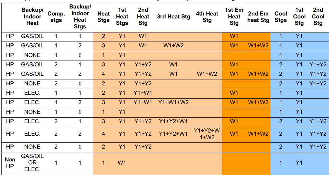

Table 6. Installation Checklist
| Item Number | Item | Yes | No |
| 1 | Is the thermostat level where mounted on the wall? | ||
| 2 | Is the thermostat installed away from direct sunlight or dis charge air vents? | ||
| 3 | Has the thermostat been wired correctly based on the type of equipment installed (air handler, outdoor unit and accessories? | ||
| 4 | Is the thermostat wiring secured tightly to the terminals? | ||
| 5 | Is the common wire (terminal C) connected? | ||
| 6 | Has the System Test Mode located under the installer settings been used to verify proper operation? |
REFERENCE:
Download Manual: Lennox CS7500 Color Touchscreen Programmable Thermostat Installation and Setup Guide
![]()
Lennox CS7500 Color Touchscreen Programmable Thermostat Installation and Setup Guide