INNCOM e529.RF PROGRAMMABLE Thermostat
Objective
This document addresses two audiences
- The installation technician tasked with installing and configuring the e529.RF for operation within a room and, perhaps, as part of a network
- INNCOM engineering personnel tasked with preparing the e529.RF for service
Introduction
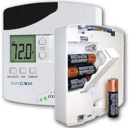
The e529.RF battery-operated thermostat, part of the INNCOM e4 family, provides easily configurable energy management. The thermostat’s Direct Digital Control processor, coupled with on-board sensors and wirelessly connected to other controllers and INNCOM devices, can provide expandable monitoring and governance of HVAC, lighting, and many kinds of guestroom amenities. Without the need for power input, the e529.RF affords great placement options for optimal performance with virtually any fan coil unit, heat pump, or packaged terminal air conditioner found in guestrooms. The programmable e529.RF maintains temperature within prescribed limits for unoccupied rooms, a range that narrows when the system determines occupancy (using the e529.RF’s Passive Infrared [PIR] detector or upon receiving a signal from a door-mounted sensor). When connected to INNCOM’s centrally controlled system, additional energy savings are achieved by using a broader setback band when the guestroom is un-rented. The e529.RF can also apply wider temperature set-back bands when the room is in hibernation during the off-season. The e529.RF uses radio frequency (RF) technology to interact with other INNCOM devices in the guestroom Integrated Room Automation System (IRAS). RF signals work well within a guestroom or suite, penetrating solid objects and even walls (see Appendix 1 for an FAQ on INNCOM’s RF technology). The entire application (e529.RF and other devices) may be connected to a networked server, through either RF technology or by wire. The e529.RF is readily expandable to include functionality such as humidity control, outside temperature display, mini-bar access reporting, occupancy reporting to housekeeping, automatic control of lights, and much more. The RF transceiver can also be used to connect the e529.RF to various INNCOM guest control devices such as the Guestroom Digital Assistant.
Application Overview
The e529.RF is designed to work in conjunction with an HVAC controller to monitor and maintain room temperature (other devices may also be controlled from the e529.RF). There are three general scenarios for using the e529.RF:
- A basic IRAS application with the e529.RF communicating wirelessly to another device
- An IRAS application with RF communication to a network backbone
- An IRAS application with wired communication to a network backbone
The commissioning/configuration procedures for these 3 scenarios are detailed in Sec.4.
All Final Products containing the INNCOM TXR 02-9994 must contain the following statements on their label:
This device contains FCC ID: GTC029994TXR.
This device complies with part 15 of the FCC Rules. Operation is subject to the following two conditions:
- This device may not cause harmful interference, and
- this device must accept any interference received, including interference that may cause undesired operation.
The followings statements are required in the final product user manuals:
This equipment has been tested and found to comply with the limits for a Class A digital device, pursuant to Part 15 of the FCC Rules. These limits are designed to provide reasonable protection against harmful interference when the equipment is operated in a commercial environment. This equipment generates, uses, and can radiate radio frequency energy and, if not installed and used in accordance with the instruction manual, may cause harmful interference to radio communications. Operation of this equipment in a residential area is likely to cause harmful interference, in which case the user will be required to correct the interference at his own expense. All Final Products containing the TXR 02-9994 should be kept at a safe distance of at least 20cm from all persons. The final product cannot be co-located with any other antenna or transmitter. Modifications not expressly approved by INNCOM International Inc. could void the user’s authority to operate the equipment.
Installation
Specifications
- Dimensions: 4.7” W × 4.7” H × 1.2” D (119 mm x 119 mm x 30 mm)
- Operating Range: 41°F to 149°F (5°C to 65°C)
- Temperature: ± 1°F 60°F to 85°F (± 0.5°C 15°C to 30°C)
- Power In: Four AA Batteries
- Battery Life: approximately 2 years
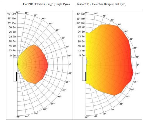
- PIR Range:
- RF Range: 100 ft
- Light Sensor: 255 levels of light sensitivity
Placement
Since RF is critical to the e529.RF’s operation, placement of the device and careful consideration of possible sources of interference are important. For instance, the unit should not be placedclose to floor or ceiling or near pipe or other metal pieces.
To minimize external conditions interference with room temperature measurement, locate the e529.RF away from external doors or windows and areas in direct sunlight.
Mounting Instructions
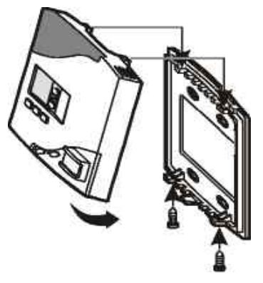
- Separate the e529.RF body and the mounting plate by pulling the bottom of the mounting plate away from the e529.RF body and then pull the mounting plate down.
NOTE: If the back-mounting plate is rotated more than 2 or 3 degrees, the plastic tabs at the top of the plate may fracture or break off. - Attach the mounting plate to the wall or electrical box with the arrow embossed on the mounting plate pointing upward.
- The e529.RF is provided with four 6-32 ¾” sheet metal screws for mounting the plate to an existing 4” × 4” electrical box. If attaching the mounting plate to sheetrock or a similar wall surface, install four 6-8 × ¾ anchors. The four holes on the mounting plate can be used to mark the location for the anchors.
- Install the four AA alkaline batteries (NOTE: Use alkaline batteries only) provided into the battery compartment located on the rear of the e529.RF. Depress the battery clamp latch at the top of the battery compartment and then swing open the battery clamp. Insert the 4 AA alkaline batteries, matching the “+” terminals on the batteries to the “+” symbols in the battery compartment. Close the battery clamp and verify the latch is securely fastened.
- Verify that the e529.RF display is now showing information. If the display is blank, verify that the batteries are completely installed with the right polarities and that the batteries are not dead.
- Hook the tabs at the top rear of the e529.RF housing into the matching depressions at the top of the mounting plate and rotate the bottom of the e529.RF housing toward the wall until it snaps into place on the mounting plate.
- Secure the e529.RF housing to the mounting plate with the two small screws provided with the e529.RF. The screws thread into two small holes on the bottom of the e529.RF housing (see figure above).
Features and Functions
e529.RF Interface
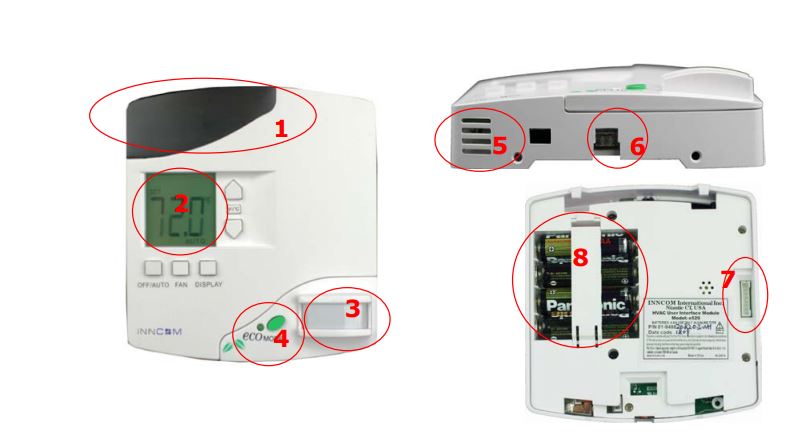
- Optional IR Transmitter.
- LCD Display and Control Buttons –Display setting used in configuring controls
- Passive Infrared Motion Sensor (PIR)—Occupancy sensor installed in the e529.RF. Detects in-room motion
- ecoMode™ button—Activates additional energy-saving options
- Temperature and Humidity Sensors—Measure room temperature and humidity (optional)
- Light Sensor—Detects the level of light in the room and can be used for energy management
- In-Circuit Programmer Header—Provides the ability to upload new software to the e529.RF to upgrade features. [Note: Used exclusively at the factory]
- Battery Compartment
LCD Display
The LCD screen (which is backlit for 5 seconds when any function button is pressed) normally shows temperature and other indicators. During the commissioning/configuration process, the LCD is used to display the settings for establishing a unique room profile (e.g., room ID, RF channel in use, and addresses of other devices bound to the e529.RF, etc.—see bound to the e529.RF, etc.—see shown in the e529.RF display below does not represent the actual display in use. It shows all possible display elements turned on for demonstration purposes.
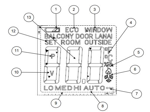
- Low Battery Indicator: Displays icon when the AA alkaline batteries need replacement
- ecoMODE™. Display: Indicates that guest is participating in enhanced environmental programs such as larger temperature setback, reduced housekeeping (of sheets and towels, for instance), and the like
- Door/Window Open: Displays position of window, lanai, or balcony door (if S541.RF sensor(s) installed)
- Temperature Scale: Displays Fahrenheit (°F) or Celsius (°C)
- Relative humidity reading
- Not used at present
- Communications: A dot indicates communication has been established with another device.
- Control/Fan Mode: Displays fan operation (OFF/AUTO).
- Fixed Fan speed (LO MED HI)
- A “V” indicates a value set for a parameter.
- A “P” indicates a parameter or sub parameter (i.e., a parameter under one of the parameters listed in section 3.2). A value may be set here.
- Value Display: Displays either the Set (target) temperature or the measured Room temperature (or, optionally, the Outside temperature).
- Temperature Reading: Displays Set (target), Room (measured), or (optionally, if networked to an exterior sensor) Outside temperature
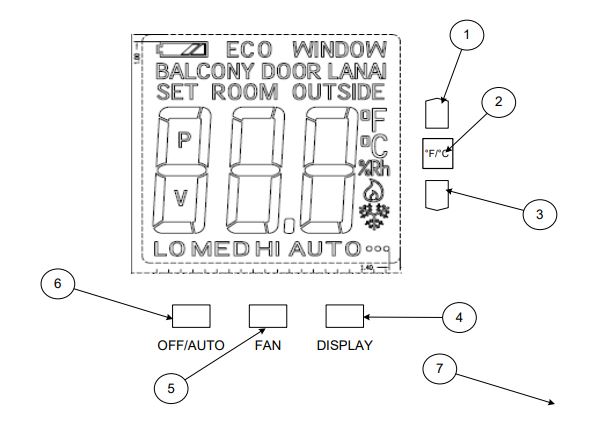
- Up Arrow: Raises temperature.
- °F/°C: Toggles temperature readings between Fahrenheit and Celsius scales.
- Down Arrow: Lowers temperature.
- Display: Cycles the LCD between the Set (selected) temperature and the measured Room temperature. [Outdoor temperature may also be displayed if the system is networked to a server or the Web broadcasting readings from an outside sensor.].
- Fan: Forces the fan into a fixed speed. The first press sets low (LO) speed, pressing again sets medium (MED), and another press sets high (HI). The fan speed cycle begins again with the next push.
- OFF/AUTO: In Auto mode, AUTO is displayed along with the target (Set) temperature. The controller will automatically adjust valve and fan speed to maintain the set temperature. In Off mode, OFF is displayed and the HVAC does not run as long as the room temperature is within safety limits. Note: some HVAC systems require the fan to run at minimal speed even if Off is selected.
- Not Pictured: ecoMODE™ button (see Section 2 Interface). Used to participate in an enhanced energy and resource saving program.
Service Mode
An installation technician enters the e529.RF’s Service Mode to set parameters for uniquely identifying a room, binding the INNCOM devices in the room to that identity, setting the operational characteristics of the devices, and, if necessary, connecting the room to floor- or building-wide network.
Entering Service Mode
All input to the e529 is initiated in the Service Mode. To enter Service Mode
- Press and hold the °F/°C button on the e529.RF
- Press and release the OFF/AUTO button
- press and release the DISPLAY button
- Release the °F/°C button
The LCD will display the parameters shown below (Sec. 3.2.1) [Note: The e529.RF’s uses a function-driven commissioning/configuration system rather than the parameter/value entry used in earlier e-series thermostats]. Scroll through the selections using the Up/Down arrow buttons. A menu will remain selected for 1 minute, then the LCD will revert to its default display.
Entering Values in Service Mode
- rId— Sets Room ID, a number that uniquely identifies the room to other device or on a network. Room ID consists of 5 digits divided into 3 bytes of data labeled HIMEDLO (default is 65535). The number will be included on the commissioning list and generally corresponds to the actual room number.
- Enter Service Mode
- At rId, press OFF/AUTO; the Room ID scrolls across the LCD, then the first digit (HI) appears
- Use the Up/Down arrow to scroll to the first number of the Room ID entry from the commissioning list (HI values can be from 0 to 6)
- Accept the HI number by pressing Display. The MED value will now show on the LCD
- Enter the MED 2 digits in the same manner (value 0–99). LCD shows LO
- Enter the LO 2-digit value (0–99). On pressing Display, the new rId will scroll across the LCD, then the e529.RF returns to the menu list
- PAn—The ID number of a network coordinating device, e.g., a B574, in a network bridge application. The number will be included on the commissioning list.
- Enter Service Mode if not already there
- Scroll to PAn and press OFF/AUTO
- Use the Up/Down arrows to find the PAN ID on the commissioning list.
- Press Display. The e529.RF beeps to confirm the Pan ID value is stored, and the LCD returns to the menu list.
- rF—Selects the RF channel for IRAS communication. The number will be included on the commissioning list.
- Enter Service Mode if not already there
- Scroll to rF and enter using OFF/AUTO.
- Use Up/Down to set the RF channel between 11 and 26.
- Press Display. The e529.RF beeps to confirm the value is stored and the LCD returns to menu
- Adr—Used to “teach” IRAS devices the unique identification information (e.g., Room ID, PAN ID, I/O map for a room) that binds them to a room or network.
- Enter Service Mode if not already there
- Scroll to Adr and enter using OFF/AUTO
- Prepare the partner device to learn from the e529.RF (see Sec. 4.1)
- Scroll to the Address for the device to be taught (from the commissioning list)
- Press Display. The unit will send the teach command on all RF channels (11–26), then the LCD displays the selected address
- Accept in partner device (see Sec. 4.1)
- [Note: When in Address mode, the FAN button can be used to Reset the target device.]
- Io—Used to configure the Input/Output map of a partner device. [Note: Some INNCOM devices can have variable roles in a room, e.g., an S217 can be configured to control a light or a switch. The device roles are contained in the I/O map.]
- Enter Service Mode if not already there
- Scroll to Io and enter using OFF/AUTO
- Prepare the partner device to learn from the e529.RF (see Sec. 4.1)
- Scroll to the Address for the device to be taught (from the commissioning list)
- Press Display. The unit sends the I/O map out over all channels
Note: Whenever a device is taught information, it is important to verify that the instruction was received and accepted by “pinging” the device. See PnG below.
- SEr—Used to configure Partner (Server) devices. Refer to the e528 Parameter Guide.
- Loc—Menu of local parameters. This menu is typically not used by Installation
Technicians. The entry below is provided solely for informational purposes. The list of local parameters below will change and grow.- Enter Service Mode if not already there
- Scroll to Loc and enter using OFF/AUTO. The LCD shows a “P” and a number for each parameter (0–255).
- Select a parameter; press OFF/AUTO again to get the value of the parameter
- P0, 2: Set Room ID (Room ID should be set using rId)
- P2, 3: Set PAN ID (set PAN ID using the PAn parameter). Not required for RF
- P4: Set the transmission (Tx) radio power. Tx may need to be boosted to meet local conditions.
- P5: Set the RF channel (set RF channel using the rF parameter)
- P6: Set the e529.RF local address (default is 13)
- P7: Set the P5 channel (default channel is 1)
- p8: Set P5 partner (default partner is e528.36_X529.RF)
- P28: Calibrate the humidity sensor
- P29: Calibrate temperature sensor (no calibration used for temperature setting in the e529.RF)
- run—Selects built-in tests of the e529.RF
- Enter Service Mode if not already there
- Scroll to run and enter using OFF/AUTO.
- Use the UP/DOWN arrows to select one of the following tests. Use the Display button to begin test execution
- 1—Reset: On execution, the LCD screen flashes red, then briefly shows reset information from a bound device
- 2—CI Connectivity test
- 3—Broadcast Room ID and PAN ID to RF bridge device
- 11—PIR test: On execution, the LCD shows Pir and the unit emits a buzzing noise when movement is detected by the passive infrared module.
- 12—Door Test: On execution, the e529 responds with a beep when the door switch is actuated
- 20—Reset counter: On execution, the LCD displays the number of times that the unit has been reset, then reverts to the test number
- 23— Press Display to start a real-time temperature test. The Set temperature ticks up every second for one minute.
- 24—Tests room relative humidity (if sensor available)
- 25—Tests the built-in light sensor
- 26—Tests battery power (255 = full charge)
- PnG—Sends a signal to connected devices and registers response
- Enter Service Mode if not already there
- Scroll to PnG
- Scroll to the address of the device to be pinged. After 2 seconds, the version of the partner device will begin to scroll across the LCD, verifying communication with the e529.RF
Note: Pressing Display after a device has been pinged allows entry into the NVRAM of partner devices. Activity in the NVRAM space can severely affect functionality. This parameter should be used only by INNCOM technicians.
Commissioning Process
As noted in the Application Overview, the e529.RF may be employed in 3 scenarios:
- An in-room IRAS application, with the e529.RF controlling devices in the guestroom
- An IRAS connected by wire to a network and server
- An IRAS connected by RF to a network and server
For each scenario, establishing the unique room ID, binding devices, and establishing communication will be different.
In-Room IRAS
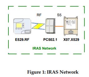
- Set the Room ID in the e529.RF. The thermostat is then capable of “teaching” the IDs to other devices and thus binding them to the room application (see Sec. 3.2 on selecting and entering values).
Open the rId menu and reset the number from the default (65535) to the number designated on the commissioning list - Prepare the partner device to learn Room ID from the e529.RF.
- On every partner device, there is a method for opening a device to listen for the information transmitted in the teach command. Find the “key” (e.g., an input or diagnostic button and possibly labeled Bind, or Diag, or Bind/Diag,) and use it to prepare the partner device—in Figure 1 above, the PC502.1 has a small recessed button labeled Bind on the back. (In each product, the “key” is pressed 3 times in succession to be put into Binding mode).
- In the example above, use a small pointed device (e.g., a straightened paper clip) to press the PC502.1’s Bind key recessed button 3 times. The device will now will be ready for binding for the next 2 minutes. [Note: the device will also enter the binding mode for 2 minutes on powering up. This provides an opportunity to change the binding if necessary.]
- Enter the Address of the partner device (see Sec. 3.2)
- Open the Adr parameter
- Enter the Address of the partner device from the commissioning list
- Send the teach command using the Display button. The partner device output LEDs will flash rapidly, indicating that the device is ready to accept the binding.
- Press the Bind, or Diag, or Bind/Diag key on the partner device to accept the Address, Room ID and RF channel from the e529.RF.
- To confirm a successful network link, a small dot in the lower right corner of the LCD display will appear within approximately 2 minutes to confirm connectivity to the HVAC server. The installer can also confirm a successful network link by pinging the partner device from the e529.RF.
IRAS to FLN5 (wired)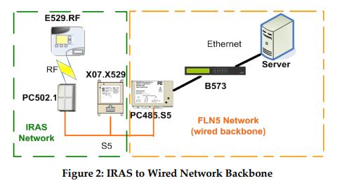
Currently, there is no Application available for this configuration.
IRAS to FLN5 (RF)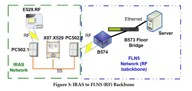
- Set the Room ID in the e529.RF. The thermostat is then capable of “teaching” the IDs to other devices and thus binding them to the room application (see Sec. 3.2 on selecting and entering values).
open the rId menu and reset the number from the default (65535) to the number designated on the commissioning list - Prepare the partner device (PC-502.1) to learn Room ID from the e529.RF.
- On every partner device, there is a method for opening a device to listen for the information transmitted in the teach command. Find the “key” (e.g., an input or diagnostic button and possibly labeled Bind, or Diag, or Bind/Diag,) and use it to prepare the partner device In Figure 1 above, a small recessed button on the back of the PC502.1.
- In the example above, use a small pointed device (e.g., a straightened paper clip) to press the PC502.1’s recessed button 3 times. The device will now will be ready for binding for the next 2 minutes.
- Enter the Address of the partner device (see Sec. 3.2)
- Open the Adr parameter
- Enter the Address of the partner device from the commissioning list
- Accept the address using the Display button. The partner device output LED’s will flash rapidly, indicating that the device is ready to accept the binding.
- Press the Bind, or Diag, or Bind/Diag key on the partner device to accept the Address, Room ID and RF channel from the e529.RF.
- To confirm a successful network link, a small dot in the lower right corner of the LCD display will appear to confirm connectivity to the HVAC server. The installer can also confirm a successful network link by pinging the partner device from the e529.RF.
- Configure the PC-502.2 (RF network)
- Open the run menu
- Set the value to 3 and press display. When Display is pressed, the e529.RF sends RF configurations to the PC-502.2.
Testing
Testing the e529.RF Operational Controls
The e529.RF and the other INNCOM devices in a room setup or network have been subjected to rigorous unit, integration, operational and production testing prior to shipment for installation. The installation technician needs only to test generally that the thermostat functions as intended.
- at power ON, confirm all segments and characters are displayed on the LCD display.
- At startup, confirm the following sequence is displayed:
- e5R
- 4,1 (application sw. version)
- Room ID (default 6,5,5,3,5)
- ScP (service)
- rAd 2,4,4,7 (radio sw. version)
- Target temperature
- Press the Display button to verify that the LCD briefly shows the Room (measured) temperature (which should be close to or equal the Set temperature). If the e529.RF is networked to an outdoor sensor, press Display again to check that outside temperature is displayed.
- Press the °F/°C button once to verify that the temperature scale changes. Verify that the LCD resets to the default scale in 5 seconds.
- Use the OFF/AUTO button to test Heat/Cool functions (depending on the HVAC system, fan operation may only subside to a minimal level). Press OFF/AUTO to return to Auto mode.
Press the FAN button to cycle fan speed from LO to MED to HI. - Press the ecoMODE™ button. Verify that the LCD displays notification that the ecoMODE™ option has been chosen. (See Sec. 2.1.1)
- Test the PIR by entering the Run menu and selecting value 11. On execution, the LCD shows Pir and the unit emits a buzzing noise when movement is detected by the passive infrared module.
- Test the door monitor by entering the Run menu and selecting value 12.
- If balcony door or window sensors are linked to the e529.RF, open the linked opening.
Verify that the e529.RF displays notification that the door or window is open.
Testing the e529.RF IRAS and RF network connections - Use the PING parameter to test each device on the network. See Sec. 3.2, PnG for instruction.
- Verify that e529.RF LCD displays dot in lower right corner of the screen indicating RF link to HVAC partner.
- Enter the RUN menu value 2. Execute a test of the IWAN. If the test is successful, the Room ID will scroll across the LCD, indicating communication with the server.
Ordering Information
Detailed ordering information for the e529 can be found in the e529 Order Guide.
INNCOM RF FAQ
The radio frequency (RF) end of the electromagnetic spectrum allows for wireless propagation of signals through space through a wide range of frequencies, from the very low (9 kilohertz [kHz] to the very high (300 gigahertz [GHz]). Unlike wavelengths from the “light” end of the spectrum (infrared, visible light), RF penetrates many solid objects and thus is not dependent on line of sight for transmission. That fact, combined with the low power consumption typical for in-room communication, makes RF a good choice for guestroom controls.
Q. What RF transceivers are used by INNCOM?
A. INNCOM radios feature a customizable software protocol that allows for many different operating conditions, encryption, and traffic allocation schemas.
Q. What are the operating specifications for the INNCOM RF?
A. Physical and Media Access 802.15.4
- Frequency 2400-2483.5 MHz: worldwide use, up to sixteen channels.
- Media Access CSMA/CA Carrier Sense Multiple Access / Collision Avoidance.
- Modulation Direct Sequence Spread Spectrum (DSSS)
- Topology Peer-to-peer; Repeater capability
- Transmission power 0dB, 20dB, U. FL
- Range 0dB Approx. 40 ft / 15 m indoor transmission distance; 30 mA 20dB Approx. 90 ft / 30 m indoor transmission distance; 120 mA
- U. FL Approx. 90 feet / 30 m indoor transmission distance; 30 mA
Q. Are there physical or environmental constraints to the use of RF?
A. INNCOM RF operates in the same unlicensed 2.4 GHz frequency band as 802.11 (WiFi), Blackberries, and other equipment; the frequency band can be quite crowded, and heavy traffic conditions can impair performance. An evaluation of the installation place for the presence andpossible impact of other RF applications is highly desirable. There are also physical considerations: Devices should not be placed close to floors and ceilings, to metal pieces or to pipes containing water. The proximity of other RF antennas, from an 802.11 access point, laptops or cell phones, should also be considered. If a distributed antenna system (DAS) is present, make sure that the frequency band is available and that the DAS is not overpowering the INNCOM RF frequencies.
Q. What channel should I use for the e529.RF?
A. Based on a site survey, INNCOM assigns channels to rooms (indicated on the commissioning list). There are multiple considerations in the use of RF channels in commissioning a room or network with INNCOM devices. An RF channel by itself is indiscriminate; theoretically, any device on a particular channel can interact with any other device on that same channel. Given RF communication range, without some way of further segregating transmission, an e529.RF could end up talking to a device several rooms away from where it is installed. INNCOM overcomes this problem using the Room ID and device addressing. By binding a device address to a Room ID associated with an RF channel, INNCOM can segregate the e529.RF’s application room by room. Adjacent rooms may use the same channel without interference or crosstalk because the devices within each room are bound to an individual room ID.
REFERENCE:
DOWNLOAD MANUALS:
INNCOM e529.RF PROGRAMMABLE Thermostat User Manual
