IEC E055-71520317 Programmable Fan Coil Thermostat
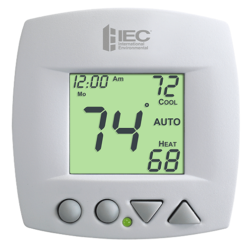
Auto-Changeover is available in 4-pipe systems, in 2-pipe systems with Electric Heat, or when used with a G100-71520306 accessory, auto-changeover sensor.
CAUTION
Follow Installation Instructions carefully. Disconnect the Power to the Heater/Air Conditioner before removing the old thermostat and installing the new thermostat.
PREPARATION
 Proper installation of the thermostat will be accomplished by following these step-by-step instructions. If you are unsure about any of these steps, call a qualified technician for assistance.
Assemble tools
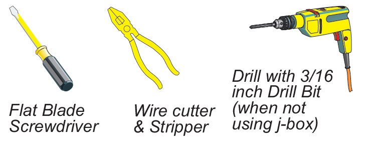
- Make sure your Heater/Air Conditioner is working properly before beginning the installation of the thermostat.
- Carefully unpack the thermostat. Save the screws, wall anchors, and instructions.
- Turn off the power to the Heating/Air Conditioning system at the main fuse panel.
REMOVE & REPLACE THE OLD THERMOSTAT
- Remove the cover of the old thermostat.
- If it does not come off easily check for screws.
- Loosen the screws holding the thermostat base or subbase to the wall and lift away.
- Disconnect the wires from the old thermostat. Tape the ends of the wires as you disconnect them and mark them with the letter of the terminal for easy reconnection to the new thermostat.
- Keep the old thermostat for reference purposes until your new thermostat is functioning properly.
Note: This thermostat is strictly a low-voltage control. One or two E025-71481103 (10a 125vac) or E025-71481104 (20a 125vac) relay boards must be installed to operate the fan coil unit.
MOUNT THE THERMOSTAT
- The thermostat can be mounted directly to the wall or onto the unit when required. An optional wall mounting plate is available from IEC when an existing hole in the wall is too large for the thermostat or when mounting to a junction box (the thermostat by itself will not completely cover a 2 x 4 junction box).
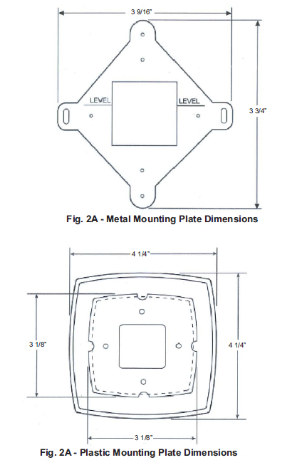
- If the mounting plate is to be used, install the mounting plate on the wall or junction box. The mounting plate has 2 parts: the metal mounting plate (see fig. 2A) and the plastic mounting plate (see fig. 2B).
- The accessory mounting plates are available in different sizes. Accessory mounting plate part numbers are G100-71520311 (5.75” x 6.25”), G100-71520310 (4.62” x 4.62”), and G100-71520312 (7” x 4.25”).
- Install the metal mounting plate to the wall or junction box with 2 screws provided. Use the outermost screw holes.
- Place the plastic mounting plate over the metal mounting plate. Be sure the wiring exits through holes in both mounting plates. The plastic mounting plate is secured to the metal mounting plate when the thermostat mounting base is installed.
- Remove the thermostat cover from the back plate by grasping the top and bottom of the cover
squeezing together while pulling apart to expose mounting holes and wiring connections see (Fig 1). - Route the thermostat wires through the large hole in the thermostat mounting base. Remove outer sheath from wires for added flexibility. Standard solid or multi-conductor thermostat wire should be used from the thermostat to the unit. Size and length considerations are as follows: for a maximum of 100’ use 18 AWG wire.
- If accessory mounting plate is not used: Level the back plate against the wall and mark the wall through the 2 mounting holes in the base. Drill 2 3/16” mounting holes in the wall where marked. Mounting holes are provided if installing on unit. Secure back plate to the wall or unit with 2 screws and anchors provided. Ensure all wires exit through hole in back plate.
- If accessory mounting plate is used: Secure the metal mounting plate against the wall with the 2 screws provided. Use the outermost screw holes. Drill 2 3/16” mounting holes in the wall where marked.
- Mounting holes are provided if installing on unit. Secure back plate to the wall or unit with 2 screws provided. The thermostat base should fit securely in the indentation provided in the plastic mounting plate. Ensure all wires exit through hole in the mounting base.
- Adjust wire length and routing to allow proper closure of the thermostat. Strip each wire at the end no more than 1/4” to prevent wires from shorting together. Match and connect wires to terminals on the thermostat.
- Push excess wiring into wall. Seal hole in the wall to prevent drafts.
- Re-attach thermostat cover to back plate.
- Turn on power to unit. The thermostat will receive power from the fan coil unit.
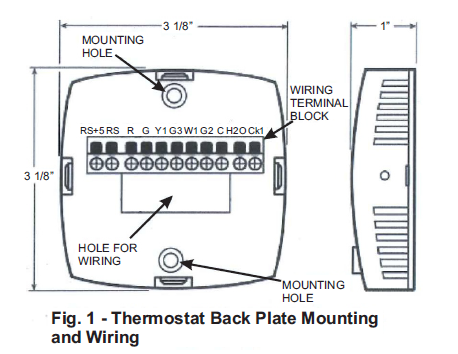
WIRE CONNECTIONS
If the terminal designations on your old thermostat do not match those on the new thermostat, refer to the chart below, or the wiring diagrams that follow.
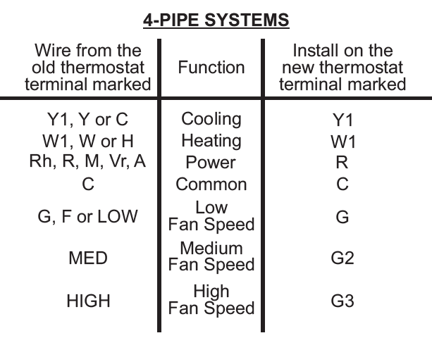
Note: Be sure to seal any opening through the wall behind the thermostat to prevent improper temperature sensing of the conditioned space.
If the terminal designations on your old thermostat do not match those on the new thermostat, refer to the chart below, or the wiring diagrams that follow.
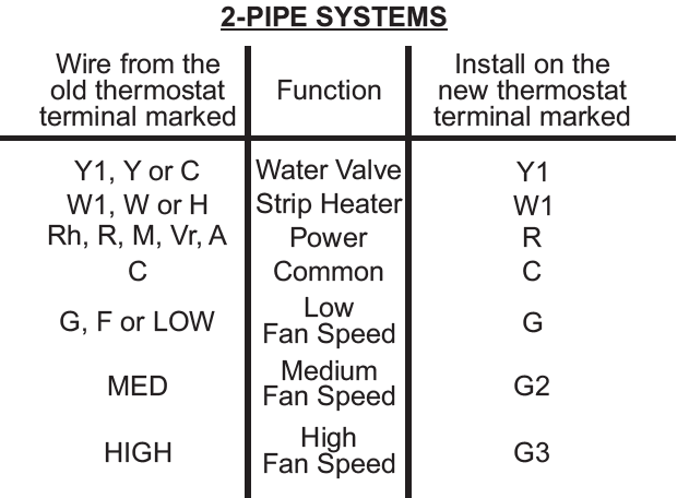
Note: Be sure to seal any opening through the wall behind the thermostat to prevent improper temperature sensing of the conditioned space.
Sample Wiring Diagram
4-Pipe, 2 Relay Boards, Line Voltage Water Valves
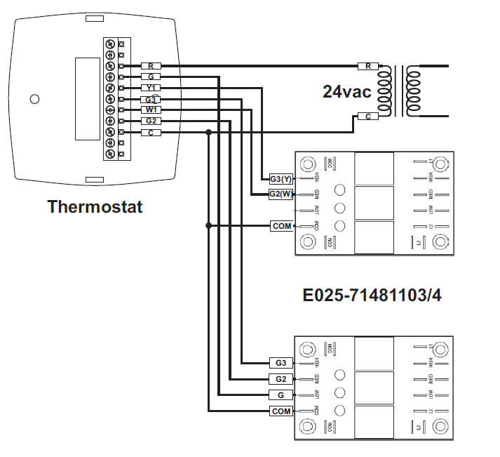
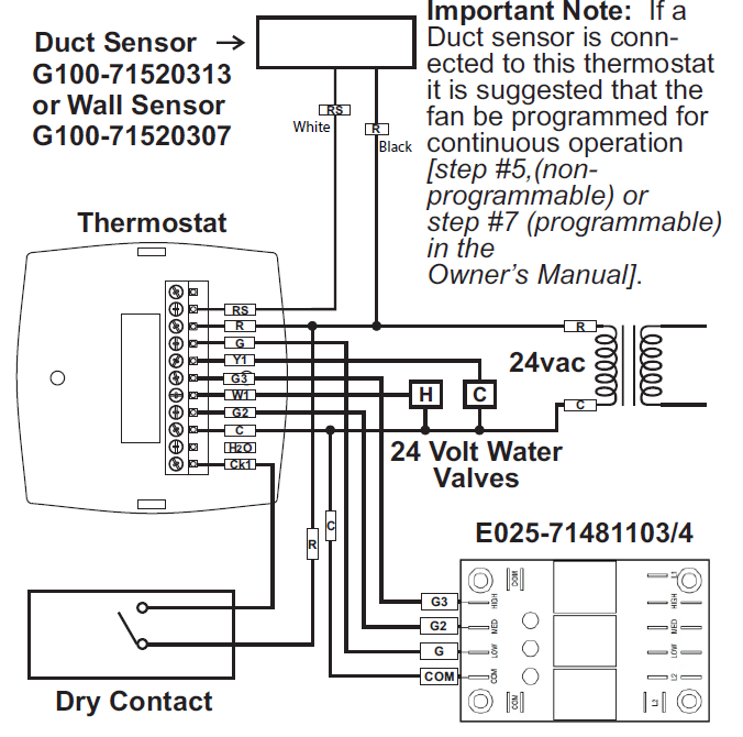
4-Pipe, Low Voltage Valves, Remote Temperature Sensor & Dry Contact
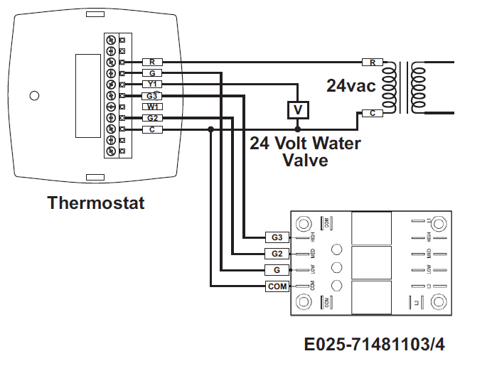
2-Pipe, Low Voltage Valve, Heat Only or Cool Only
2-Pipe, Low Voltage Valve, H2O Changeover Sensor
Important Note: If a Duct sensor is conn-ected to this thermostat it is suggested that the fan be programmed for continuous operation [step #5,(non-programmable) or step #7 (programmable) in the
Owner’s Manual].
2-Pipe, Low Voltage Valve, Chilled Water with Electric Strip Heat
TEST OPERATION
Turn the power on to the Fan Coil Unit.
Press the MODE button repeatedly until the HEAT icon appears on the display. Press the UP or DOWN buttons until the set temperature is 10 degrees above room temperature. The hot water valve will open and the fan will be run.
Press the MODE button repeatedly until the COOL icon appears on the display. Press the UP or DOWN buttons until the set temperature is 10 degrees below room temperature. The cold water valve will open and the fan will be run.
Press the UP button until the setpoint is equal to the room temperature. Press the Fan button repeatedly until a single bar appears next to the Fan icon. Confirm the fan is running on low speed. Press the Fan button again, confirm the fan is running on medium speed. Again, press the Fan button, confirm the fan is running at high speed. Press the Fan button once more, the bars next to the Fan icon should disappear.
Press the MODE button repeatedly until the OFF icon appears on the display. Both valves will be closed and the fan will be off.
2-PIPE, CHANGEOVER SENSOR, NO STRIP HEAT
Turn the power on to the Fan Coil Unit and confirm that the thermostat is programmed correctly in setup. Steps #3 & #4 (non-programmable) or Steps #5 & #6 (programmable) in the Owner’s Manual.
If hot water is available, press the MODE button repeatedly until the HEAT icon appears on the display. Press the UP or DOWN buttons until the set temperature is 10 degrees above room temperature. The hot water valve will open and the fan will be running.
If cold water is available, press the MODE button repeatedly until the COOL icon appears on the display. Press the UP or DOWN buttons until the set temperature is 10 degrees below room temperature. The cold water valve will open and the fan will be running.
Press the UP button until the setpoint is equal to the room temperature. Press the Fan button repeatedly until a single bar appears next to the Fan icon. Confirm the fan is running on low speed. Press the Fan button again, and confirm the fan is running on medium speed. Again, press the Fan button, confirm the fan is running at high speed. Press the Fan button once more, the bars next to the Fan icon should disappear.
Press the MODE button repeatedly until the OFF icon appears on the display. Both valves will be closed and the fan will be off.
2-PIPE, NO CHANGEOVER SENSOR
Turn the power on to the Fan Coil Unit and confirm that the thermostat is programmed correctly in setup. Steps #3 & #4 (non-programmable) or Steps #5 & #6 (programmable) in the Owner’s Manual.
If hot water is available, press the MODE button repeatedly until the HEAT icon appears on the display. Press the UP or DOWN buttons until the set temperature is 10 degrees above room temperature. The hot water valve will open and the fan will be running.
If cold water is available, press the MODE button repeatedly until the COOL icon appears on the display. Press the UP or DOWN buttons until the set temperature is 10 degrees below room temperature. The cold water valve will open and the fan will be running.
Press the UP button until the setpoint is equal to the room temperature. Press the Fan button repeatedly until a single bar appears next to the Fan icon. Confirm the fan is running on low speed. Press the Fan button again, confirm the fan is running on medium speed. Again, press the Fan button, confirm the fan is running at high speed. Press the Fan button once more, the bars next to the Fan icon should disappear.
Press the MODE button repeatedly until the OFF icon appears on the display. Both valves will be closed and the fan will be off.
Turn the power on to the Fan Coil Unit and confirm that the thermostat is programmed correctly in setup. Steps #3 & #4 (non-programmable) or Steps #5 & #6 (programmable) in the Owner’s Manual.
If hot water is available, press the MODE button repeatedly until the HEAT icon appears on the display. Press the UP or DOWN buttons until the set temperature is 10 degrees above room temperature. The hot water valve will open and the fan will be running. The strip heat will be locked out if hot water is available.
If hot water is not available, but your unit is equipped with a strip heat system, press the UP or DOWN buttons until the set temperature is 10 degrees below room temperature. The unit should energize the strip heaters and the fan will be running.
If cold water is available, press the MODE button repeatedly until the COOL icon appears on the display. Press the UP or DOWN buttons until the set temperature is 10 degrees below room temperature. The cold water valve will open and the fan will be running.
Press the UP button until the setpoint is equal to the room temperature. Press the Fan button repeatedly until a single bar appears next to the Fan icon. Confirm the fan is running on low speed. Press the Fan button again, confirm the fan is running on medium speed. Again, press the Fan button, confirm the fan is running at high speed. Press the Fan button once more, the bars next to the Fan icon should disappear.
Press the MODE button repeatedly until the OFF icon appears on the display. Both valves will be closed and the fan will be off.
SYMPTOM: The fan will not run in all three speeds or switches speeds in an improper order. CAUSE: Incorrect wiring between the thermostat and the relay board, or between the relay board and the fan wires.
REMEDY: Recheck the wiring (G=low speed, G2=medium speed, G3=high speed).
SYMPTOM: Cold water valve opens for either a cool or a heat demand in a 4-pipe system. CAUSE: The thermostat has been programmed for the incorrect type of fan coil.
REMEDY: Confirm that you have entered the correct programming for your type of fan coil system. Steps #3 & #4 (non-programmable) or Steps #5 & #6 (programmable) in the Owner’s Manual.
SYMPTOM: The water valve does not open at all in 2-pipe configurations.
CAUSE: The thermostat has been programmed for the incorrect type of fan coil system or the fan coil is not wired to the thermostat correctly. REMEDY: Program the thermostat for a 2-pipe fan coil. Step #3, (non-programmable) or Step #5 (programmable) in the Owner’s Manual. Also, make certain that the water valve is wired to the Y1 terminal.
SYMPTOM: Parts of the thermostat display are missing.
CAUSE: The thermostat has been programmed for a minimal display.
REMEDY: Program the thermostat for Full Display. Step #1, (non-programmable) or Step #3 (programmable) in the Owner’s Manual.
SYMPTOM: The thermostat displays large set-point digits instead of the room temperature. CAUSE: The thermostat has been programmed to display Single Setpoint.
REMEDY: Program the thermostat to display Dual Setpoint. Step #2 (non-programmable) or Step #4 (programmable) in the Owner’s Manual.
SYMPTOM: The thermostat display is stuck in Unoccupied.
CAUSE: The sensor connected to the Dry Contact terminals of the thermostat, is active, forcing the unit into ‘Unoccupied.’
REMEDY: Verify proper wiring between the thermostat and the occupancy sensor and verify that the wiring is not shorted.
If no sensor is connected, program the Dry Contact polarity for Normally Open. Step #11
(non-programmable) or Step #14 (programmable) in the Owner’s Manual.
TROUBLESHOOTING
SYMPTOM: The thermostat will only allow Heat or Off in 2-pipe installations, even though chilled water is available.
CAUSE: Faulty, improperly wired, or improperly installed H2O changeover sensor.
REMEDY: Confirm proper wiring of the change-over sensor (between R and H2O). Confirm proper placement of the sensor (good mechanical coupling for temperature transfer).
Test the changeover sensor as follows:
- Remove power from the fan coil system.
- Disconnect the wire between the sensor and the H2O terminal.
- Place an ohmmeter between R and the wire just disconnected from the sensor.
- A good sensor will show continuity whenever the water temperature is confirmed to be at or below 65 degrees. If the sensor is open when the water temperature is confirmed to be at or below 65, replace the sensor.
5000 W I-40 Service Road Oklahoma City, OK 73128 405.605.5000 [phone] 405.605.5001 www.iec-okc.com 008 – 2019 International Environmental Corporation (IEC).
Reference
Download Manual:
IEC E055-71520317 Programmable Fan Coil Thermostat Installational Instruction
OTHER MANUALS
IEC E055-71520317 Programmable Fan Coil Thermostat Owners Manual
Iec E055-71520317 Programmable Fan Coil Thermostat Product Specifications Guide

IEC E055-71520317 Programmable Fan Coil Thermostat Installational Instruction