hotowell HTW-WF01-FC Smart Wifi Fan Coil Thermostat
General
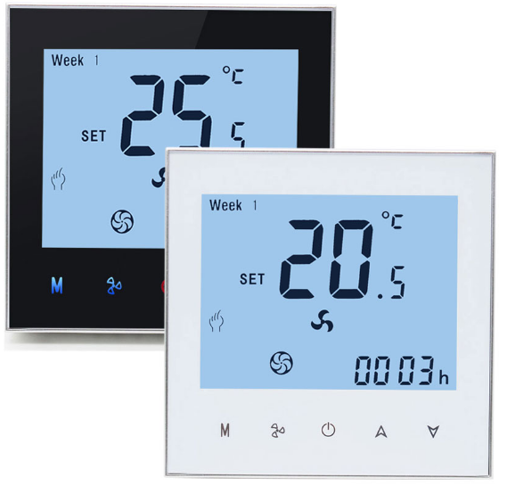
HTW-WF01-FC series Smart Wifi fan coil thermostat is widely used in this environment like Homes, Residential buildings, Schools, Hotels, Hospitals, Offices and etc. to main an ideal room temperature purpose.
Features
- 17 Mainstreaming Languages synchronize in APP(English, Spanish, Russian, Hungarian, Turkey, Hebrew, German, Italian, Japanese, French, Poland, simplified Chinese, traditional Chinese, Holland, Portuguese, Vietnamese, Arabic, Korean)
- Snap-In Easy Installation
- Fit for EU & Standard Junction Electric Box

- Easily Work with Amazon Echo, Google Home, Tmall Genie, IFTTT
- Group Control in 1 App
- Fashion Sense of Science and Technology
Ordering Guide
| Ordering Guide | |||||
| HTW-WF01- FC-** | -2 | 2 pipe(tube) system | -W | Wifi application | |
|
Smart Wifi Fan Coil Thermostat |
-4 | 4 pipe(tube) system | -T | Clock | |
| -M | Modulating output | -P | Programmable | ||
| -N | Modbus RTU communication | -E | External Temperature Sensor | ||
| -K | Key Card occupancy input | -24v | Power Supply with 24Vac | ||
| e.g. HTW-WF01-FC-2KP refers to application: 2 pipe(tube) system, 3 fan speed + 1 H/C valve, with key card and weekly programmable | |||||
| Typical Wiring | |||||
Typical Wiring

A=HTW-WF01-FC-2
- 2 pipe(tube) system
- 3-speed fan
- NO/NC valve
B= HTW-WF01-FC-4
- 4 pipe(tube) system
- 3-speed fan
- 2 NO/NC valve
C=HTW-WF01-FC-MN
- 3-Speed fan output
- 1 a load of Modulating 0~10V output
- Modbus Communication
Specification
| Specification | |||||
| Power Supply | 95~240Vac, 50/60Hz | Sensor | N±TC3950, 10±K ℉ | ||
| Current Load | Fan Relay 5A(3A-inductive) | Temperature Accuracy | 0.5°C or 1 | ||
| Valve Relay 3A(1A-inductive) | Set-Point Range | 5~35°C | |||
| Storage Temp. | -5 ~ 45 °C | Display Temp. Range | 5 ~ 99°C | ||
| Power Consumption | < 1.5W | Timing Error | < 1% | ||
| Housing Material | PC +ABS ( Fireproof) | Installation Box | EU or Standard Electric Box | ||
| Wires on Terminals | Wire 2 x 1.5 mm2 or 1 x 2.5 mm2 | ||||
| Protection Class | IP20 | Operating Buttons | Capacitive Touch Buttons | ||
| Installation | |||||
Installation

WARNING: RISK OF ELECTRICAL SHOCK. Disconnect the power supply before making an electrical connection. Contact with components carrying hazardous voltage can cause electrical shock and may result in severe personal injury or death
- Make sure the power is OFF! Try turning ON your heating/cooling system by changing the temperature.
- If you can’t get the system to turn ON in 5 minutes, you’ll know the power is OFF.
- Take off the installation faceplate by rotating and gently pulling, then connect voltage supply/load output/external sensor(if with) wires respectively to appropriate terminals.
- Fix the installation plate onto the electric junction box with screws packed in the box.
- Fasten the thermostat display part and the installation faceplate through the groove. (Installation process completed)
Dimensions and Display
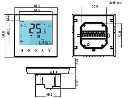
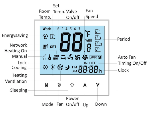
Operation
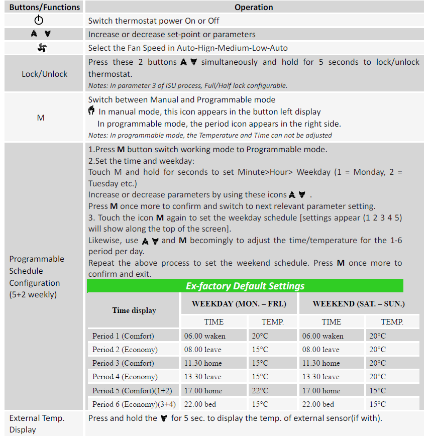
Notes: During the thermostat in wifi connected status, it runs the programmable schedule process made from the APP prior to that of the thermostat. i.e. The programmable schedule only can be carried out if there is no Wifi connection between the thermostat and the smartphone/tablet PC. The installation personnel with non-professional training shall not perform this operation! During the thermostat power off, Press these 2 buttons M & simultaneously, and hold for 5 seconds to enter the ISU process. Press
  to adjust the configurable parameter value, and press M to switch to the next parameters. The ISU process will automatically exit and be confirmed after 5 seconds with no operation.
| Parameter | Function | Configurable Value | Default | ||
| 1 | Temperature calibration | -7°C to +9°C (internal sensor) | -1 | ||
|
2 |
Fan Control Type |
00:When room temp. reaches set point, the fan turns off
01:When room temp. reaches set point, the fan turns to low |
00 | ||
|
3 |
Keypad Lock type |
00: = All buttons will lock except the Power button
01: = All buttons will lock |
01 | ||
| 4 | Heating/Cooling | 00: Cool only 01:Heating and Cooling | 01 | ||
| 5 | Min. set-point limit | 5°C – 15°C | 05 | ||
| 6 | Max. set-point limit | 15°C – 45°C | 35 | ||
| 7 | 12/24 hours format | 00:12h 01:24h | 01 | ||
|
8 |
Temperature Display |
00:display both set-point and room temp.
01:display set-point only |
00 | ||
|
9 |
Economy Mode |
00:Normal mode
01:Energy Saving mode |
00 | ||
|
A |
Heating Economy
Temperature |
10°C – 30°C | 20 | ||
| B | Cooling Economy
Temperature |
10°C – 30°C | 26 | ||
| C | Dead Zone | 1°C to 5°C (Switching differential) | 1 | ||
Warranty
- Products are warranted for 2 full years (checking and repairing services) from the date of purchase which products are not being damaged by any man-made factors.
- Service outwith the warranty period may incur an extra charge.
- For more details please contact Hotowell directly.
Wifi Connection
Step 1- Download and Install the APP
Use your smartphone or tablet PC to scan the QR code below or Search “SMART LIFE” in the app store /Google Play to download and install the APP.

Step 2- Register your account
- Open the “SMART LIFE” application, and click “Allow” on the pop-up notification dialog(fig 2.1)
- Press the “register” button on the register page(fig2.2)
- Select your region and type in your phone No. or email (fig 2.3) then you may get a verification code.
- Type in your password and confirm (fig 2.4) to complete your registration.
- If you already have an account, please just log in.

Step 3- Connect App with Thermostat
On the thermostat
During power-off status, press and hold the arrow icon  for 8 sec until the connecting icon
  appears on the thermostat screen and flashes once a sec.
On the App
- Press the “+” on the upper right corner of the page (see Fig 3.1) or “Add Device” to add “Thermostat”.
- Click “Confirm indicator rapidly blink” (Fig 3.2) then select your network and back to your App to enter the password of your wireless router(Fig.3.3) and confirm.
- The App will connect with the thermostat successfully. The connecting process takes 5~90 sec, the thermostat name can be editable once connected.(Fig.4.4)

Alternative AP mode Connection
If the thermostat has already been connected under the above steps, please ignore this process. This SMART LIFE App is only supported on 2.4GHz Wi-Fi channels. If the router does not be supported, the Wi-Fi signal is weak or the thermostat can not be connected as above steps, please try this AP mode connection process.
On the thermostat
- During power-off status, press and hold the arrow icon for 8 sec until the connecting icon appears on the thermostat screen and flashes once a sec.
- Press and hold the arrow icon for 8 sec again, the icon
 will flash once per 3 sec.(fig 4.1) indicating connecting from normal router mode.
 - Indicates connecting from AP mode.
On the App
- Click “Confirm indicator slowly blink” (fig 4.1) then select your network and back to your app to enter the password of your wireless router (fig 4.2) and confirm. The app will go to the page(fig 4.3)
- Press “Connect now” to select the wifi signal Smart life-XXXX from the thermostat(fig 4.3).
- This AP mode connection process may typically take approx. 5~90 seconds to complete.
- The thermostat name can be edited after connection (fig 4.4).

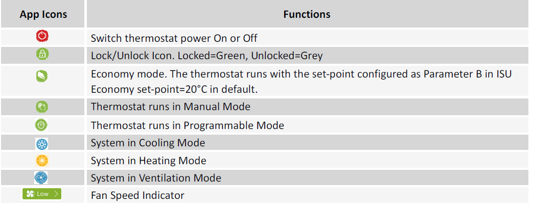
Operation Icons on APP
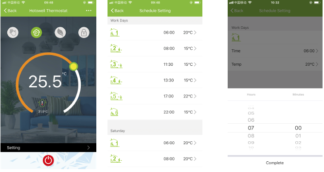
Programmable Schedule Setting
When the thermostat runs in programmable mode, click the “schedule setting” to switch to the schedule page, where you can simply configure the weekly programmable 5+2 schedule for up to 6 periods each day. (Workdays=Monday~Friday, Weekend=Saturday and Sunday) Click “Complete” to save the configuration.
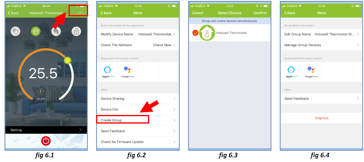
Group Control and Info. Modify
- Press the menu button as Fig 6.1, then click “Create Group”. Select all the rooms you want and confirm. (fig 6.2 and Fig 6.3), edit the group name or ungroup as Fig 6.3 and Fig 6.4
- Group Control allows controlling all thermostat (+∞ units) configurations in the group at the same time
Share Thermostat with Others
- Method 1: Click “Share with Familay” as Fig 4.4.
- Method 2: Click “Profile”>” Sent”>” Add”>Switch on the device>” Share with New Member”>Type in the telephone number you would like to share.
- Method 3:Home page of the device>Menu(as fig 6.1)>” Device Sharing”>” Add”>>Type in the telephone number you would like to share with.
Work with 3rd party Echo Control
Click “Profile”>” Integration”>Select amazon echo/Google Home/IFTTT>” Use Now” Details as below in Fig 7.1 and 7.2.

Customize Scene
- This process is to customize your own personal scenes to suit your needs, for example, set your home temperature automatically when you come back home.
- There are 4 scenes in the default setting and can be added/deleted at will.
- Here set an example of a specific scene: “leave home for holiday” and turn on the thermostat when the temperature is lower than 5°C
- Scenes(fig 8.1)>+>Enter a name for the scene(fig 8.2)>Add a condition(Below 5°C as fig 8.3)>Add a Task(fig 8.4)>Save

Trouble Shooting
| Trouble Shooting | ||||
| No. | If… | Then… | ||
| 1 | The power is on but without display. | n Check if the terminals between the LCD panel and Relay/Power Module is loose. | ||
| 2 | Without output but display works. | n Use a new LCD panel or new Relay/Power
Module for Replacement |
||
| 3 | Room Temp. on display is not correct | n Do temperature calibration in parameters in ISU | ||
|
4 |
The heating system does not respond | n Set the mode to heating by pressing the M button. n Make sure the temperature is set above the room temperature. n Make sure the “heat on” icon shows on the display. n Wait 5 minutes for the system to respond. |
||
| 5 | The M or Increase/Decrease button doesn’t work | Make sure the keypad is unlocked. Check that thermostat is on. |
||
Notice: Hotowell reserves all the right for the final explanation. The manual is subject to change without further notice.
REFERENCE:
DOWNLOAD MANUALS:
hotowell HTW-WF01-FC Smart Wifi Fan Coil Thermostat User Manual

hotowell HTW-WF01-FC Smart Wifi Fan Coil Thermostat User Manual