Honeywell TB7100A1000 MultiPRO Multispeed Thermostat

APPLICATION
The TB7100A1000 MultiPRO™ Multispeed and Multipurpose Thermostat provide electronic control of 24 Vac heating and cooling systems.
See Table 1 for a description.
Table 1. TB7100A Thermostat Description.
| Feature | Description |
| Powering Methods | • Battery only
• 24 Vac only • 24 Vac with battery backup |
| System Types | • Conventional (1 Heat, 1 Cool stage)
• Heat Pump (up to 2 Heat,1 Cool stage) • 2 Pipe Fan Coil • 2 Pipe Fan Coil with Auxiliary Heat • 4 Pipe Fan Coil • PTAC (up to 2 Heat, 1 Cool) |
| Changeover | Manual or automatic changeover selectable |
| System Setting | Heat-Off-Cool-Auto |
| Fan Setting | Auto, On |
| Fan Speeds | Low, Medium, and High |
| Remote Setback | Remote Setback Input for occupancy sensor or DDC setback |
| Fan Ramping Algorithm | VersaSpeed™ Fan Ramping Algorithm for automatic fan speed selection (fan coil and PTAC applications) |
MERCURY NOTICE
If this control is replacing a control that contains mercury in a sealed tube, do not place your old control in the trash. Dispose of it properly. Contact your local waste management authority for instructions regarding recycling and the proper disposal of an old control.
INSTALLATION
When Installing this Product…
- Read these instructions carefully. Failure to follow them could damage the product or cause a hazardous condition.
- Check ratings given in instructions and on the product to ensure the product is suitable for your application.
- The installer must be a trained, experienced service technician.
- After installation is complete, check out product operation as provided in these instructions.
CAUTION
Electrical Shock or Equipment Damage Hazard.
Can shock individuals or short equipment circuitry.
Disconnect the power supply before installation.
Select Thermostat Location
Select a location for the thermostat about 5 ft (1.5m) above the floor in an area with good air circulation at an average temperature. See Fig. 1.
Do not install the thermostat where it can be affected by:
- Drafts or dead spots behind doors and in corners.
- Hot or cold air from ducts.
- Radiant heat from sun or appliances.
- Concealed pipes and chimneys.
- Unheated (uncooled) areas such as an outside wall behind the thermostat.
Separate Wallplate from Thermostat
- Separate the wallplate from the thermostat. See Fig. 2.

Install Wallplate (See Fig. 3)
Mount the thermostat horizontally on the wall:
- Pull the wires through the wire hole on the wallplate.
- Position the wallplate on the wall with the arrow pointing up. Level the wallplate for appearance only.
- Use a pencil to mark the mounting holes.
- Remove the wallplate from the wall and drill two 3/16 in. holes in the wall (if drywall) as marked. For firmer material such as plaster, drill two 7/32 in. holes. Tap the wall anchors (provided) into the drilled holes until flush with the wall.
- Pull the wires through the wire hole on the wallplate and position the wallplate over the wall anchors.
- Insert the mounting screws into the wall anchors and tighten them.

WIRING
IMPORTANT
- All wiring must agree with applicable codes, ordinances and regulations.
- use 18 gauge thermostat wire. Shielded cable is not required.
NOTES:
- Sensor wires must have a cable separate from the thermostat control cable.
- Refer to Table 2 for terminal designation descriptions.
- See Fig. 6 through 17 for wiring diagrams for specific equipment applications.
- Select set of terminal identifications that correspond to your system type (conventional or heat pump). (See Fig. 4).

- Loosen screw terminals used for the application.
- Insert the wires into the terminal block and tighten each screw terminal.
- Push excess wire back into the wall opening and restrict wires to the shaded area. See Fig. 5.

- Plug the wall opening with nonflammable insulation to prevent drafts from affecting the thermostat
| Terminal Designation | Description |
| RC (see Note 1) | Power for cooling—connect to secondary side of cooling system transformer. |
| R (see Note 1) | Power for heating—connect to secondary side of heating system transformer. |
| Y | Compressor output. |
| C (see Note 2) | Common wire from secondary side of cooling system transformer. |
| W1 | Heat relay. Auxiliary heat relay to heat pump, PTAC. |
| G | Fan relay. Low fan speed for Fan Coil and PTAC applications. |
| G2 | Fan relay. Medium fan speed for Fan Coil applications only. |
| G3 | Fan relay. High fan speed for Fan Coil and PTAC applications. |
| O/B (see Note 3) | Changeover valve for heat pumps. |
| S1 (see Note 4) | Indoor remote sensor, remote setback, or changeover input. |
| S2 (see Note 4) | Indoor remote sensor, remote setback, or changeover input. |
NOTES:
- When used in a single-transformer system, leave metal jumper wire in place between RC and R. If used on a two-transformer system, remove metal jumper wire between RC and R.
- Common wire is optional when thermostat is used with batteries. When using separate transformers for heating and cooling, the common must come from the cooling transformer.
- If thermostat is configured for a heat pump in the Installer Setup, configure changeover valve for cool (O-factory setting) or heat (B).
- Sensor wires must have a cable separate from the thermostat control cable.
Table 3. Wiring Diagrams
|
System Type |
Wiring Diagram Figure |
| Standard Heat/Cool (1H/1C) | 6, 7 |
| Heat Only | 8 |
| Heat Only with Fan | 9 |
| Cool only | 10 |
| Heat Pump (No Auxiliary Heat) (1H/1C) | 11 |
| Heat Pump (with Auxiliary Heat) (2H/1C) | 12 |
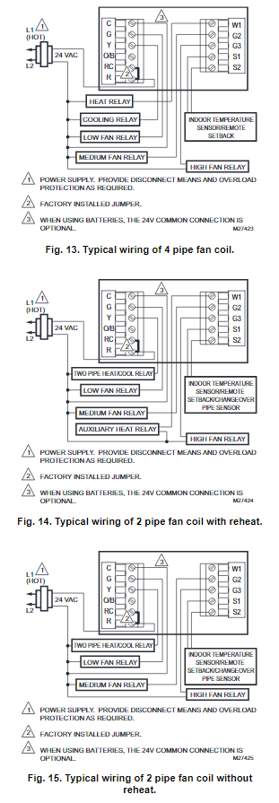
| 4 Pipe Fan Coil | 13 |
| 2 Pipe Fan Coil (with Auxiliary Heat) | 14 |
| 2 Pipe Fan Coil (no Auxiliary Heat) | 15 |
| PTAC 1H/1C (High speed, Low speed fan) | 16 |
| PTAC 2H/1C (High speed, Low speed fan) | 17 |
| Multiple TR21 Sensors | 18, 19, 20 |
| Multiple C7189U Sensors | 21 |
Conventional System

Wiring Heat Pump System Wiring

Fan Coil System Wiring
PTAC System Wiring

Sensor Wiring for Temperature Averaging


POWER THE THERMOSTAT
You can choose from three methods to power the thermostat:
- Batteries only (AA alkaline).
- 24 Vac direct connection only.
- 24 Vac direct connection with battery backup (AA alkaline).
Wiring 24 Vac Common - Single-Transformer System—Connect the common side of the transformer to the C screw terminal of the thermostat wallplate. Leave the metal jumper wire in place between RC and R.
- Two-Transformer System—Connect the common side of the cooling transformer to the C screw terminal of the thermostat wallplate. Remove the metal jumper wire between RC and R.
Installing Batteries

- Install two AA alkaline batteries on the back of the thermostat as marked. See Fig. 22.
- Locate and remove the tab labeled Remove. See Fig. 23.

IMPORTANT
This tab must be removed in order to set the real-time clock.
Mount Thermostat to Wallplate
- Align the terminal screw blocks with the pins on the back of the thermostat.
- Push the thermostat straight onto the wallplate until it snaps into place. See Fig. 24.

- Push the thermostat straight onto the wallplate until it snaps into place. See Fig. 24.
SETTING CALENDAR AND TIME
This thermostat is designed to, under normal use, automatically keep current time and day in memory for up to ten years once the calendar is set. There are two ways to set the calendar and time for this thermostat:
SETTING DATE/TIME WHEN THERMOSTAT IS FIRST POWERED
When the thermostat is first powered, the display is ready to set the calendar and time. The thermostat proceeds through a sequence of setup screens. See Fig. 25.
SETTING DATE/TIME AFTER THERMOSTAT IS ALREADY FUNCTIONING
Use the installer setup to set year, month and day. See the Installer Setup Numbers, Settings, and Tests section.
ADVANCED SETTINGS
The thermostat has advanced settings to match the HVAC system. These settings can be adjusted to match specific needs. See the following section (Installer Setup Numbers, Settings, and Tests) for details.
INSTALLER SETUP NUMBERS, SETTINGS, AND TESTS (TABLE 4)
Configure Installer Setup
- Press and release the System key.
- Press System and Done keys simultaneously.
- Hold keys for approximately five seconds, until the screen changes.
- When the display changes, release the System and Done keys.
NOTE: See Table 4 for installer setup (ISU) numbers and settings.
Installer System Tests
Use the Installer System Test section to test the heating, cooling and fan. Refer to the latter portion of Table 4.
CAUTION
Equipment Damage Hazard.
Minimum compressor off time is bypassed during Installer System Test
Avoid cycling compressor quickly.
IMPORTANT
Use Installer System Test to test heating, cooling and fan. The setting chosen for System Type (Installer Setup Number 0170) can prevent some System Test Numbers from appearing.
Table 4. Installer Setup Menu.
| Installer Setup Number |
Installer Setup Name |
Default Setting |
All Settings |
Notes |
| 0120 | Date (Year Upper) | 20 | 20—21 | Available year range: 2001 – 2178 |
| 0130 | Date (Year Lower) | 08 | 00-99 | Available year range: 2001 – 2178 |
| 0140 | Date (Month) | 6 | 1-12 | |
| 0150 | Date (Day) | 15 | 1-31 (Month Dependent) | |
| 0160 | Schedule Options | 4 | 0—Non-Programmable 4—Programmable | |
| 0170 | System Selection | 1 | 1—1H/1C Conv 2—1H w/o fan 3—1H with fan 4—1C
5—1H/1C HP 6—2H/1C HP 7—4 pipe Fan Coil 8—2 pipe Fan Coil 9—2 pipe Fan Coil w/ Aux Heat 10—PTAC 1H/1C (Hi speed, Lo speed Fan) 11—PTAC 2H/1C (Hi speed, Lo speed Fan) |
Relay Y is used for 2 pipe fan coil output relay. |
| 0180 | Heat Fan Operation | 0 | 0—Fossil 1—Electric | Only shows up if conventional system with heat stages and fan capability is selected (ISU 0170). If heat pump is selected, fan defaults to electric. If fan coil or PTAC modes are selected, fan defaults to electric (does not show up). |
| 0185 | Pre-occupancy Purge Duration | 0 | 0—no duration 1—one hour 2—two hours 3—three hours | Shown only if system has fan and schedule is programmable (ISU 0160).
Pre-occupancy purge is enabled by a nonzero duration. |
| 0190 | Reversing Valve O/B | 0 | 0—O (O/B On Cool)
1—B (O/B On Heat) |
Only shown if heat pump or PTAC system is selected. |
| 0220 | Cycles Per Hour (CPH) for first stage cooling/compressor | 3 | 1-6 | Only shown if system has cool stages (ISU 0170). Shown for heat pump, fan coil, PTAC, and conventional cooling stages. |
| 0240 | CPH for first stage heat | 5 | 1-12 | Only shown if system is conventional with heat stages, 4 pipe fan coil, 2 pipe fan coil (ISU 0170). |
| 0270 | CPH for Em Heat | 9 | 1-12 | Only shown if HP with reheat, 2 pipe fan coil with reheat, and PTAC with reheat (ISU 0170). |
| 0280 | Continuous Backlight | 0 | 0—No
1—Yes |
Always shown; however, if AC power is not present, the option is overridden and normal backlight operation occurs. |
| Installer Setup Number |
Installer Setup Name |
Default Setting |
All Settings |
Notes |
| 0300 | Changeover | 1 | 0—Manual 1—Auto | Only shown if system has both heat and cool stages (ISU 0170). Shown for CNV, HP, PTAC and 4 pipe fan coil (ISU 0170). Not shown for 2 pipe fan coil modes. |
| 0310 | Deadband | 3°F (2°C) | 2 (1.5)—2°F (1.5°C)
3 (2.0)—3°F (2.0°C) 4 (2.5)—4°F (2.5°C) 5 (3.0)—5°F (3.0°C) 6 (3.5)—6°F (3.5°C) 7 (4.0)—7°F (4.0°C) 8 (4.5)—8°F (4.5°C) 9 (5.0)—9°F (5.0°C) |
Only shown if Automatic Changeover selected (ISU 0300). |
| 0320 | Temperature Indication Scale | 0 | 0—°F
1—°C |
|
| 0330 | Daylight Saving | 1 | 0—Disabled 1—Enabled (US) | |
| 0340 | Remote Temp Sensor/Remote Setback/ Changeover Input | 0 | 0—None
1—Remote 10K Indoor 2—Remote 20K Indoor 3—Changeover 2 pipe Fan Coil modes only 4—Changeover 2 pipe Fan Coil modes only |
Only shown on models that offer remote sensing.
NO input (default mode is Heat) NO input (default mode is Cool) |
| 0340
(Non- program mable) |
Remote Temp Sensor/Remote Setback/ Changeover Input | 0 | 0—None
1—Remote 10K Indoor 2—Remote 20K Indoor 3—Changeover 2 pipe Fan Coil modes only 4—Changeover 2 pipe Fan Coil modes only 5—Remote Setback
6—Remote Setback |
Only shown on models that offer remote sensing.
NO input (default mode is Heat) NO input (default mode is Cool) Hotel card NO, with 1 second software delay going from UnOcc to Occupied; 2 minute delay going from Occupied to UnOcc. Hotel Card NC, with 1 second software delay going from UnOcc to Occupied; 2 minute delay going from Occupied to UnOcc. |
| 0341 | Delay for Remote Setback | 0 | 0—No Delay
2—2 Minute Delay |
Only shown if Remote Setback (ISU 0340) is enabled. |
| 0342 | Override Option (only available in non-programmable mode) | 0 | 0—No Override 1—Override | This option is only available for non-programmable mode (ISU 0160) |
| 0343 | Unoccupied Heating Setpoint (only when remote setback enabled) | 60°F | 50-65°F
10-18°C |
|
| 0346 | Unoccupied Cooling Setpoint (only when remote setback is enabled) | 80°F | 75-90°F
24-30°C |
|
| 0347 | Fan Ramping | 1 | 0—Disabled (Lo, Med, Hi) 1—Enabled | To enable the fan ramping algorithm. Only available for fan coil or PTAC applications. |
| 0348 | Fan Mode | 0 | 0—User can choose Cycle or Constant 3 speed: Low->Med-> High->Auto-> Low
1—Cycle Only – Auto only |
To select a particular fan mode: Auto is the fan ramp mode. If ramping is not selected, fan mode automatically defaults to Low Med High (Constant only) and ISU 0348 is unavailable. Only available for fan coil or PTAC applications. |
| Installer Setup Number |
Installer Setup Name |
Default Setting |
All Settings |
Notes |
| 0349 | Auto Fan Reset | 0 | 0—Inactive
1—Reset back to Auto after 2 hours
2—Reset back to Auto after 4 hours |
The timer will be set after the user selects the constant fan speed. Fan will be set to Auto automatically when time out. The start time is calculated after initial call for heat/cool is satisfied, then 2 hour timing begins.
The timer will be set after the user selects the constant fan speed. Fan will be set to Auto automatically when time out. The start time is calculated after initial call for heat/cool is satisfied, then 4 hour timing begins. Only available for fan coil or PTAC applications. |
| 0535 | Temporary Occupied Duration Limit | 3 | 0–12 hours | 0 means no limit. |
| 0540 | Number of Periods | 4 | 2—2 Periods
4—4 Periods |
Does not appear if Non-programmable is chosen (ISU 0160).
Applies to all days of the week. If 2 is selected the Cancel Period option will not appear on the display. |
| 0580 | Minimum Compressor Off Time | 5 | 0—Off
2—2 minutes 3—3 minutes 4—4 minutes 5—5 minutes |
Only shown if system has cool stages in CNV, Heat Pump, PTAC (ISU 0170). |
| 0600 | Heat Temperature Range Stops | 90 | 40 to 90°F (4 to 32°C) | Only shown if system has heat stages (ISU 0170). |
| 0610 | Cool Temperature Range Stops | 50 | 50 to 99°F (10 to 37°C) | Only shown if system has cool stages (ISU 0170). |
| 0640 | Clock Format | 12 | 12—12 Hour
24—24 Hour |
|
| 0650 | Extended Fan-on time Heat | 0 | 0—Off
90—90 seconds |
Not displayed if fan set to fossil or cool only systems (ISU 0170) |
| 0660 | Extended Fan-on time Cool | 0 | 0—Off
40—40 seconds |
Only shown if system has cool stages. (ISU 0170) |
| 0670 | Keypad Lockout | 0 | 0—Unlocked 1—Partial Lockout 1
2—Partial Lockout 2 3—Partial Lockout 3 4—Fully Locked |
Unlocked: All functions accessible. Partial 1: Locks out schedule and system changes.
Partial 2: Locks out schedule, system, and fan changes. Partial 3: Locks out schedule, system, fan, and up/ down arrow changes. Full: Entire interface locked/non-functional. |
| 0680 | Temperature Control Heat | 2 | 1—Less Aggressive 2—Standard
3—More Aggressive |
Only shown if system has heat stages (ISU 0170). Only integral gains are affected by this setting. The setting affects control operation in all control regimes (not just recovery or setpoint change). |
| 0685 | Recovery Heat Ramp Rate | 5 | 0-20°F/hour | Only shown if system has heat stages (ISU 0170). 0 disables the ramped recovery (step setpoint change at period start time). |
| 0690 | Temperature Control Cool | 2 | 1—Less Aggressive 2—Standard
3—More Aggressive |
Only shown if system has cool stages (ISU 0170). Only integral gains are affected by this setting. The setting affects control operation in all control regimes (not just recovery or setpoint change). |
| 0695 | Recovery Cool Ramp Rate | 3 | 0-20°F/hour | Only shown if system has cool stages (ISU 0170). 0 disables the ramped recovery (step setpoint change at the period start time). |
| Installer Setup Number |
Installer Setup Name |
Default Setting |
All Settings |
Notes |
| 0700 | Temperature Display Offset | 0 | -3 (-1.5)— -3°F (-1.5°C)
-2 (-1.0)— -2°F (-1.0°C) -1 (-0.5)— -1°F (-0.5°C) 0 (0.0)—0°F (0.0°C) 1 (0.5)—1°F (0.5°C) 2 (1.0)— 2°F (1.0°C) 3 (1.5)—3°F (1.5°C) |
This offset applies to both the control temperature and to the display temperature for indoor sensor (and remote indoor sensor). |
| 0710 | Restore Factory Defaults | 0 | 0—No
1—Yes |
Resets all ISU parameters to default values and resets the schedule to default energy savings (see Table 5). Retains only calendar settings and time. |
| 0720 | Screen Display | 2 | 0—Display Room Temperature 1—Display Setpoint 2—Display Both | |
| INSTALLER TESTS | ||||
| Test 1 | Installer Test Cool | 0 | 0—Off
1—Cool Stage 1 |
Only shown if system has cool stages. |
| Test 2 | Installer Test Fan | 0 | 0—Off
1—Fan Stage 1 2—Fan Stage 2 3—Fan Stage 3 |
Only shown if system has fan. |
| Test 3 | Installer Test Heat | 0 | 0—Off
1—Heat Stage 1 2—Heat Stage 2 |
Only shown if system has fan.
Systems with 2 Heat stages will have option 2 enabled for Installer Test 3. |
| Test 4 | Installer Test EM Heat | 0 | 0—EM Heat Off 1—EM Heat On | Only shown if multi-stage HP is selected (heat pump with more heating than cooling stages). |
OPERATION
- Fan Sequence Operations (ISU 347, 348, 349)
If heat pump or conventional application modes are enabled in ISU 170, then ISU 347 is not available for fan ramp algorithm. The fan operates as a default ON/AUTO selection that works the same way as our CommercialPRO TB7220 thermostat. There is only one fan relay output that is activated.
If PTAC or fan coil thermostat application modes are enabled in ISU 170, then ISU 347 is available for installer setup selection.
The thermostat comes factory default with the fan ramping algorithm enabled (ISU 347). This gives the user the ability to select Auto-Lo-Med-Hi option in ISU 348 or Auto only option in ISU 348. Auto sets the thermostat into the fan ramping algorithm mode and automatically sets the sufficient speed for PI control. Auto also automatically shuts the fan off when there is not a call for heating or cooling. If the user decides to disable ISU 347, then the fan will only have Lo-Med-Hi option available. If ISU 347 is not enabled, then ISU 348 does not appear as a user selection choice.
If ISU 347 is enabled, then ISU 349 is available as a selection choice. The user can select either a 2 hour or 4 hour timer fan reset function. The fan will reset from a constant speed to auto mode after the time period expires. If ISU 347 is not enabled, then ISU 349 does not appear as a user selection choice.
Equipment Sequence Operations (ISU 170)
- Heat Pump and Conventional
Heat Pump and conventional use a single fan speed. The single fan speed label will be G, located on the G1 terminal relay output. Label should read G/Gl to help out the installers. Display on the thermostat for these modes will give the Fan On/Auto option. There is no fan ramping algorithm, ISU 347, 348, 349 are not available. - PTAC
PTAC modes 10 and 11 will have the same selection options available as the heat pump selection options. The only difference is that the PTAC options have a Lo and Hi speed fan output instead of single speed output and that it follows the fan sequencing described above with ISU 347, 348, 349. - 4 Pipe
4 pipe is treated similar to 1H/1C conventional. It follows the fan sequencing described above with ISU 347, 348, 349. - 2 Pipe
There are two different 2 pipe modes – 2 pipe only and 2 pipe with reheat. - 2 pipe only – 2 pipe modes do not contain the ability to have automatic changeover. They are manual changeover only. The thermostat will have a priority when choosing a system mode (heat or cool). When ISU 340 has a 2 pipe changeover sensor enabled, the thermostat screen system mode will lock on heat or cool (whatever the changeover sensor is communicating to the thermostat). If ISU 340 does not have a changeover sensor enabled, then the system mode from the thermostat screen can manually be adjusted between heat or cool. It follows the fan sequencing described above with ISU 347, 348, 349.
- 2 pipe with reheat – 2 pipe modes do not contain the ability to have automatic changeover. They are manual changeover only. The thermostat will have a priority when choosing a system mode (heat or cool). When ISU 340 has a 2 pipe changeover sensor enabled, the thermostat screen system mode will lock on heat only. When the 2 pipe changeover sensor is sensing cool mode, the user can adjust to heating mode which will bring on the auxiliary heat. If ISU 340 does not have a changeoversensor enabled, then the system mode from the thermostat screen can manually be adjusted between heat or cool. It follows the fan sequencing described above with ISU 347, 348, 349.
- Special Programmable Mode Functions
Installer Setup 160 allows the thermostat to be configured for either a mode with a programmable 7 day schedule or as a non-programmable thermostat. - Preoccupancy purge (ISU 185)
This feature is available only when the thermostat is configured as a programmable schedule and when a fan is used. The fan will run 1-3 hours before the occupied schedule starting time to circulate air. - Override Button, Temporary Override (Duration Limit ISU 535)
While in the programmable schedule mode, an override button is available to perform temporary override control. The default override time can be configured through ISU 535. Lockout configuration via ISU 670 can provide restrictions on access to setpoint changes, system changes, and schedule changes. - No remote setback
The remote setback feature only works in the nonprogrammable mode.
Special Non-Programmable Mode Functions
- Override (Optional)
The override feature is optional in the non-programmable mode. The override can be configured through ISU 342. When the override is activated in the non-programmable mode it will temporarily override to a new setpoint until the end time expires. - Remote Setback
Remote Setback is available (ISU 340). Occupancy sensors, manual time clock inputs, and DDC night setback can be used to provide inputs to setback thethermostat. Unoccupied heating (ISU 343) and unoccupied cooling (ISU 346) setpoints are available to configure the setback setpoints.
System Settings
- Heat—Thermostat controls the heating system.
- Off—Both heating and cooling systems are off. Fan is turned off.
- Cool—Thermostat controls the cooling system.
- Auto—Thermostat automatically changes between heat and cool operation, depending on indoor temperature.
Fan Settings
- Auto —Fan runs only when heating/cooling system is on.
- On—Fan runs continuously.
Table 5 shows default program settings. See Owner’s Guide for complete instructions to change the program.
Table 5. Energy saving default schedule.
| Schedule Period |
Time |
Setpoints | Fan Setting | |
| Heat | Cool | |||
| Occ1 | 8:00am | 70°F (21°C) | 75°F (25.5°C) | On |
| Unocc1 | 10:00pm | 55°F (10°C) | 85°F (24°C) | Auto |
| Occ2 | 1:00pm | 70°F (21°C) | 75°F (25.5°C) | On |
| Unocc2 | 12:00pm
(Noon) |
55°F (10°C) | 85°F (24°C) | Auto |
- Minimum-Off Timer (Compressor Protection)
The thermostat has an adjustable Minimum-Off Timer that can be set from zero to five minutes (Factory Setting—five minutes). The Minimum-Off Timer can be bypassed through the Installer System Test or it can be bypassed permanently by setting the Minimum-Off Timer to 0 minutes in the Installer Setup. The Minimum-Off Timer is activated after the compressor turns off:- If the thermostat is system powered (common wire), the Minimum-Off Timer is also activated upon initial startup and after power interruptions.
- If there is a call for cooling or heating during the Minimum-Off Time, the thermostat displays “Wait.”
- When the Minimum Off Timer expires, “Cool On” or “Heat On” (heat pumps only)” appears solidly in the display and the compressor and fan turn on.
Indoor Temperature Sensor
Allow indoor temperature sensor to absorb the air for a minimum of five minutes before taking a reading. See the Sensor instructions for more information.
TROUBLESHOOTING (TABLE 6)
| Symptom | Possible Cause | Action |
| Display does not come on. | Thermostat is not being powered. | Check for 24 Vac between C and RC.
Check that AA batteries are installed correctly and are good. |
| Temperature settings do not change. | The upper or lower temperature limits were reached. | Check temperature setpoints.
Check Installer Setup Numbers 0600 and 0610; modify as needed. |
| The keypad is fully locked. | Check Installer Setup Number 0670 to change keypad locked options. | |
| Heating or cooling does not come on. | Thermostat minimum off-time is activated. | Wait up to five minutes for the system to respond. |
| System selection not set to Heat or Cool. | Set system Selection to correct position. | |
| System type Selection is incorrect. | Check Installer Setup Number 0170 and make sure correct System type is chosen. | |
| Thermostat is calling for Heat (Heat on) or Cool (Cool on) but no heating or cooling is running. | Heating or cooling equipment is not operating. | Check wiring.
Check Installer Setup Number 0170 and make sure correct system type is chosen. Verify operation of equipment in System Test mode. |
| Heat does not turn on (Heat On is solid in the display). | Heating equipment failure. | Check for 24 Vac at the equipment on the secondary side of the transformer between power and common. If voltage is not present, check the heating equipment to find the cause of the problem.
Check for 24 Vac between the heat terminal (W) and transformer common. If 24 Vac is present, the thermostat is functional. Check the heating equipment to find the cause of the problem. |
| Loose or broken wire connection between thermostat and heating equipment. | Check for 24 Vac between the heat terminal (W) and transformer common. If voltage is not present, check wire connection (loose or broken) between the thermostat and the heating equipment. |
| Symptom | Possible Cause | Action |
| Heat pump puts out cool air in the heat mode and warm air in the cool mode. | Changeover Valve (Installer Setup Number 0190) is not configured to match the changeover required by the installed heat pump. | Set Changeover Valve (Installer Setup Number 0190) to match the changeover required by the installed heat pump. |
| Both the heating and cooling equipment are running at the same time. | The heating equipment is not a heat pump but the System Type (Installer Setup Number 0170) is set to Heat Pump. | Set System Type (Installer Setup Number 0170) to match the installed heating and/or cooling equipment. |
| Heating and cooling wires are shorted together. | Separate the shorted heating and cooling wires. | |
| Cooling does not turn on (Cool On is solid in the display). | Cooling equipment failure. | Check for 24 Vac at the equipment on the secondary side of the transformer between power and common. If voltage is not present, check the cooling equipment to find the cause of the problem.
Check for 24 Vac between the cool terminal (Y) and transformer common. If 24 Vac is present, the thermostat is functional. Check the cooling equipment to find the cause of the problem. |
| Loose or broken wire connection between thermostat and cooling equipment. | Check for 24 Vac between the cool terminal (Y) and transformer common. If voltage is not present, check the wire connection (loose or broken) between the thermostat and the cooling equipment. | |
| Fan does not turn on in a call for heat (electric furnace). | Fan Control in Heating is set to System Controls Fan (Setting 0180). | Set Fan Control in Heating to Thermostat Controls Fan (Setting 0180). |
| Heating equipment is running in the cool mode. | Heating equipment is not a heat pump but System Type (Installer Setup Number 0170) is set to Heat Pump. | Set System Type (Installer Setup Number 0170) to match the installed heating and/or cooling equipment. |
| Heating equipment does not turn off and heat temperature setting is set below room temperature (Heat On is not in the display). | Heating equipment is not a heat pump but System Type (Installer Setup Number 0170) is set to Heat Pump. | Set System Type (Installer Setup Number 0170) to match the installed heating and/or cooling equipment. |
| Cannot set the system setting to Heat. | System Type (Installer Setup Number 0170) is set to Cool Only. | Set System Type (Installer Setup Number 0170) to match the installed heating and/or cooling equipment. |
| Cannot set the system setting to Cool. | System Type (Installer Setup Number 0170) is set to Heat Only or Heat Only with Fan. | Set System Type (Installer Setup Number 0170) to match the installed heating and/or cooling equipment. |
| Heat On is not in the display. | System setting is not set to Heat and/ or temperature setting is not set above room temperature. | Set the system setting to Heat and set the temperature setting above the room temperature. |
| Cool On is not in the display. | System setting is not set to Cool and/ or the temperature setting is not set below room temperature. | Set the system setting to Cool and set the temperature setting below the room temperature. |
| Wait is in the display. | Compressor minimum off timer is active. | Wait up to five minutes for the cooling or heating (heat pump) equipment to turn on. |
SPECIFICATIONS
Electrical Ratings:
|
Terminal |
Voltage (50/60 Hz) | Running Current |
| W (Heating) | 20 – 30 Vac | 0.02 – 1.0A |
| Y (Cooling) | 20 – 30 Vac | 0.02 – 1.0A |
| G (Fan) | 20 – 30 Vac | 0.02 – 0.60A |
Temperature Setting Range:
- Heating: 40°F to 90°F (4.5°C to 32°C).
- Cooling: 50°F to 99°F (10°C to 37°C).
- Operating Ambient Temperature: 0°F to 120°F (-18°C to 49°C).
- Shipping Temperature: -30°F to 150°F (-34.4°C to 65.6°C).
- Operating Relative Humidity (Non-condensing): 5% to 90%.
- Thermostat Dimensions: 3-3/4 in. (95 mm) high x 6 in.
(152 mm) wide x 1-3/8 in. (35 mm) deep. - Accessories:
C7189U Remote Indoor Sensor: 10K ohm NTC.
C7772 Flush-Mount Remote Indoor Sensor: 20K ohm NTC.
TR21 Wall-Mount Remote Indoor Sensor: 20K ohm NTC.
TR21-A Wall-Mount Remote Indoor Sensor: 10K ohm NTC. - Perchlorate Material
This thermostat contains a Lithium battery which may contain Perchlorate material.
The following statement is required:
Perchlorate Material—special handling may apply.
See www.dtsc.ca.gov/hazardouswaste/perchlorate
Automation and Control Solutions
Honeywell International Inc. Honeywell Limited-Honeywell Limitée 1985 Douglas Drive North 35 Dynamic Drive
Golden Valley, MN 55422 Toronto, Ontario M1V 4Z9
customer.honeywell.com
® U.S. Registered Trademark
© 2011 Honeywell International Inc.
62-0273—05 M.S. Rev. 03-11
Printed in the U.S.A.
REFERENCE:
Download Manual:
Honeywell TB7100A1000 MultiPRO Multispeed Thermostat INSTALLATION INSTRUCTIONS
another manual:
Honeywell TB7100A1000 MultiPRO Multispeed Thermostat OWNERS GUIDE
Honeywell TB7100A1000 MultiPRO Multispeed Thermostat INSTALLATION INSTRUCTIONS