
Honeywell T1 Pro Non-Programmable Thermostat
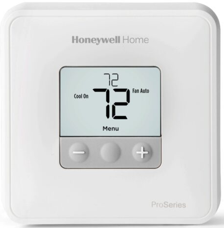
Package Includes
- T1 Pro Thermostat
- UWP™ Mounting System
- Honeywell Standard Installation
- Adapter (J-box adapter)
- Honeywell Decorative Cover Plate –
- Small; size 4-49/64 in x 4-49/64 in x 11/32 in (121 mm x 121 mm x 9 mm)
- Screws and anchors
- 2 AA Batteries
- Installation Instructions and User Guide
Optional Cover Plate Installation
Use the Optional Cover Plate when:
- Mounting the thermostat to an electrical junction box
- Or when you need to cover paint gap from old thermostat.
- Before starting, turn the power off at the breaker box or switch. Separate the Junction Box Adapter from the Cover Plate

- Mount the Junction Box Adapter to the wall or an electrical box using any of the eight screw holes. Insert and tighten mounting screws supplied with Cover Plate Kit.
- Do not over tighten Make sure the Adapter Plate is level.
- Attach the UWP by hanging it on the top hook of the Junction Box Adapter and then snapping the bottom of the UWP in place.
 Snap the Cover Plate onto the Junction Box Adapter.
UWP Mounting System installation
- Before starting, turn the power off at the breaker box or switch. Open package to find the UWP

- Position the UWP on wall. Level and mark hole positions.

- Drill holes at marked positions, and then lightly tap supplied wall anchors into the wall using a hammer.
- Drill 7/32” holes for drywall.
- Pull the door open and insert the wires through wiring hole of the UWP.

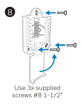
- Place the UWP over the wall anchors. Insert and tighten mounting screws supplied with the UWP. Do not overtighten. Tighten until the UWP no longer moves. Close the door. .
Power options
- Insert R and C wires into designated terminals for primary AC power (C terminal is optional if batteries are installed, but it is recommended).
- Remove wires by depressing the terminal tabs.

- Insert AA batteries for primary or backup power.

Setting Slider Tabs (built-in jumper)
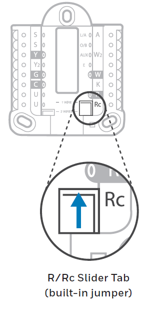
Set R Slider Tab.
- Use built-in jumper (R Slider Tab) to differentiate between one or two transformer systems.
- If there is only one R wire, and it is connected to the R, Rc, or RH terminal, set the slider to the up position (1 wire).
- If there is one wire connected to the R terminal and one wire connected to the Rc terminal, set the slider to the down position (2 wires).
UWP Wiring terminal designations
|
S |
Not used for T1 thermostat. |
L/A
– A |
Not used for T1 thermostat. |
|
| S | O/B | Changeover Valve (TH1110D only) | ||
|
Y |
Compressor contactor (stage 1) |
AUX – W2 |
Not used for T1 thermostat. |
|
| Y2 | Not used for T1 thermostat. | E | Not used for T1 thermostat. | |
| G | Fan Relay | W | Heat relay (stage 1) | |
|
C |
24VAC common. For 2 transformer systems, use common wire from cooling transformer. |
K |
Not used for T1 thermostat. |
|
| U |
Not used for T1 thermostat. |
R | 24VAC power from heating transformer* | |
| U | Rc | 24VAC power from cooling transformer* |
Wiring conventional systems: forced air and hydronics
1H/1C System (1 transformer)
- R Power [1]
- Rc [R+Rc joined by Slider Tab] [2]
- Y Compressor contactor
- C 24VAC common [3]
- W Heat relay
- G Fan relay
Heat-only System
- R Power [1]
- Rc [R+Rc joined by Slider Tab] [2]
- C 24VAC common [3]
- W Heat relay
Heat-only System (Series 20) [5]
- R Series 20 valve terminal “R” [1]
- Rc [R+Rc joined by Slider Tab] [2]
- Y Series 20 valve terminal “W”
- C 24VAC common [3]
- W Series 20 valve terminal “B”
Heat-only System
- (power open zone valve) [5]
- R Power [1]
- Rc [R+Rc joined by Slider Tab] [2]
- W Valve
- C 24VAC common [3]
1H/1C System (2 transformers)
- R Power (heating transformer) [1]
- Rc Power (cooling transformer) [1]
- Y Compressor contactor
- C 24VAC common [3, 4]
- W Heat relay
- G Fan relay
Heat-only System with Fan
- R Power [1]
- Rc [R+Rc joined by Slider Tab] [2]
- C 24VAC common [3]
- W Heat relay
- G Fan relay
Cool-only System
- R Power [1]
- Rc [R+Rc joined by Slider Tab] [2]
- Y Compressor contactor
- C 24VAC common [3]
- G Fan relay
Wiring heat pump systems
1H/1C Heat Pump System
- R Power [1]
- Rc [R+Rc joined by Slider Tab] [2]
- Y Compressor contactor
- C 24VAC common [3]
- O/B Changeover valve [7]
- G Fan relay
Thermostat mounting
- Push excess wire back into the wall opening.
- Close the UWP door. It should remain closed without bulging.
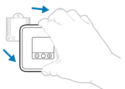
- Align the UWP with the thermostat, and push gently until the thermostat snaps in place.
- Turn the power on at the breaker box or switch.

System operation settings
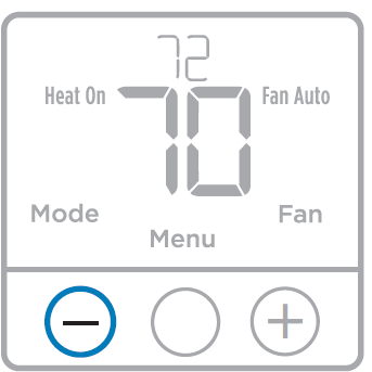
- Press the Menu to cause the Mode and Fan menus to appear.
- Press Mode () to cycle through the available modes.
System modes:
- Heat: Thermostat controls only the heating system.
- Cool: Thermostat controls only the cooling system.
- Off: Heating and cooling system is off. Fan will still operate if fan is set to On.
Fan operation settings
- Press Menu to cause the Mode and Fan menus to appear.
- Press Fan () to cycle through Fan modes
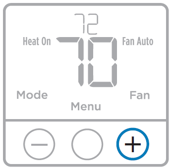
Fan modes:
- Auto: Fan runs only when the heating or cooling system is on.
- On: Fan is always on.

Installer setup (ISU)
- Press and hold Menu (center) for approximately 3 seconds to enter menu.
- Press Edit () to change values within a setup option.
- Press Next () to advance to the next setup option.
- Press Done to Save and return to the main menu screen

Installer setup options (ISU)
| # ISU | ISU Name | ISU Options (factory default in bold) |
| 125 | Temperature Indication Scale | 0 = Fahrenheit
1 = Celsius |
| 200 | Heating System Type | 1 = Conventional Forced Air Heat
2 = Heat Pump (TH1110D only) 3 = Radiant Heat 5 = None (Cool Only) Note: This option selects the basic system type your thermostat will control. |
| 205 | Heating Equipment Type | Conventional Forced Air Heat:
1 = Standard Efficiency Gas Forced Air 2 = High Efficiency Gas Forced Air 3 = Oil Forced Air 4 = Electric Forced Air 5 = Hot Water Fan Coil Heat Pump: 7 = Air to Air Heat Pump 8 = Geothermal Heat Pump Radiant Heat: 9 = Hot Water Radiant Heat 12 = Steam Note: This option selects the equipment type your thermostat will control. Note: This feature is NOT displayed if feature 200 is set to Cool Only. |
| 218 | Reversing Valve O/B | 0 = O (O/B in Cool)
1 = B (O/B in Heat) Note: This option is only displayed if the Heat Pump configured. Select whether reversing valve O/B should energize in cool or in heat. |
| # ISU | ISU Name | ISU Options (factory default in bold) |
| 220 | Cool Stages / Compressor Stages 200=Conv / 200=HP | 0, 1
Note: Select how many Cool or Compressor stages of your equipment the thermostat will control. Set value to 0 if you do not have Cool Stage/ Compressor Stage. This ISU will not be shown on TH1010D model. |
| 221 | Heat Stages | 0, 1
Note: Select how many Heat stages of your equipment the thermostat will control. This ISU will not be shown on TH1010D model. |
| 230 | Fan Control in Heat | 1 = Equipment Controls Fan
2 = Thermostat Controls Fan Note: This ISU is only displayed if ISU 205 is set to Electric Forced Air or Fan Coil. |
| 430 | Minimum Cool Setpoint | 50 °F to 99 °F (50 °F)
10.0 °C to 37.0 °C (10.0 °C) Note: The cool temperature cannot be set below this level. This ISU will not be shown on TH1010D model unless ISU 200 is set to 5 (cool only). |
| 431 | Maximum Heat Setpoint | 32 °F to 90 °F (90 °F)
0 °C to 32.0 °C (32 °C) Note: The heat temperature cannot be set above this level. This ISU will not be shown on TH1010D model unless ISU 200 is not set to 5 (cool only). |
| 1400 | Backlighting | 0 = On Demand
1 = Continuous Note: Common wire needed for continuous. This ISU will not be shown if the device is powered only by battery. |
| 1420 | Temperature Display Offset | -3 to 3F (0)
-1.5 to 1.5C (0) Note: 0 °F – No difference in displayed temperature and the actual room temperature. The thermostat can display up to 3 °F (1.5 C) lower or higher than the actual measured temperature. |
Specifications
Temperature Ranges
- Heat: 32 °F to 90 °F (0 °C to 32.0 °C)
- Cool: 50 °F to 99 °F (10.0 °C to 37.0 °C)
Operating Ambient Temperature
- 32 °F to 102 °F (0 °C to 38.9 °C)
Shipping Temperature
- -20 °F to 120 °F (-28.9 °C to 48.9 °C)
Operating Relative Humidity
- 5% to 90% (non-condensing)
Physical Dimensions in inches (mm) (H x W x D)
- 4-1/16” H x 4-1/16” W x 1-5/32” D
- 103.5 mm H x 103.5 mm W x 29 mm D
Electrical Ratings
| Terminal | Voltage (50/60Hz) | Running Current |
| W Heating | 20-30 Vac | 0.02-1.0 A |
| (Powerpile) | 750 mV DC | 100 mA DC |
| Y Compressor Stage 1 | 20-30 Vac | 0.02-1.0 A |
| G Fan | 20-30 Vac | 0.02-0.5 A |
| O/B Changeover (TH1110D only) | 20-30 Vac | 0.02-0.5 A |
EQUIPMENT DAMAGE HAZARD
Compressor protection is bypassed during testing. To prevent equipment damage, avoid cycling the compressor quickly.
ELECTRICAL HAZARD
Can cause electrical shock or equipment damage. Disconnect power before beginning installation.
MERCURY NOTICE
If this product is replacing a control that contains mercury in a sealed tube, do not place the old control in the trash. Contact your local waste management authority for instructions regarding recycling and proper disposal
Customer assistance
- For assistance with this product, please visit customer.honeywell.com.
- Or call Honeywell Customer Care toll-free at 1-800-468-1502
Automation and Control Solutions
- Honeywell International Inc.
- 1985 Douglas Drive North
- Golden Valley, MN 55422
- Honeywell Ltd
- J2X 5K8
- customer.honeywell.com
- ® U.S. Registered Trademark.
- © 2013 Honeywell International Inc.
- 69-2698EFS—03 M.S. Rev. 07-13
- Printed in U.S.A.
Reference
Download Manual:
Honeywell T1 Pro Non-Programmable Thermostat Installation Instructions
Other Manual:
Honeywell T1 Pro Non-Programmable Thermostat User Guide
Honeywell T1 Pro Non-Programmable Thermostat Installation Instructions