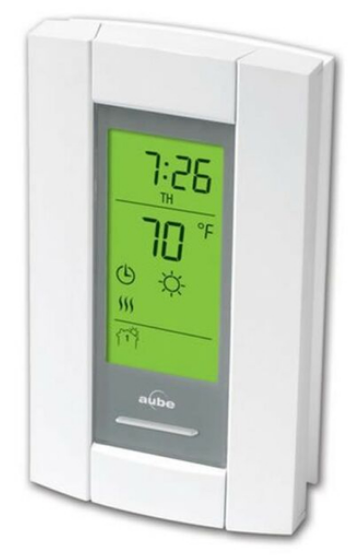
HONEYWELL PB112C-GA SMART THERMOSTAT

READ THE ENTIRE DOCUMENT BEFORE STARTING
CAUTION
- Installation must be carried out by an electrician and must comply with national and local electrical codes.
- Use this thermostat only for resistive load.
- Do NOT install the thermostat in an area where it can be exposed to water or rain.
- To prevent severe shock or electrocution, always turn the power OFF at the service panel before working with the wiring.
- Install the thermostat onto an electrical box.
- Use special CO/ALR solderless connectors if you connect the thermostat to aluminum wires.
- The thermostat is made up of two components: the control module (faceplate) and the power base. If you install another control module, ensure it is configured for 15-minute cycles.
Ground Fault Protection
This thermostat is equipped with ground fault protection. In the event of a ground fault, the ground fault protection mechanism on the thermostat trips and quickly stops the flow of electricity to prevent serious injury.
Definition of a ground fault
Instead of following its normal safe path, electricity passes through a person’s body to reach the ground. For example, a defective floor heating mat can cause a ground fault. Ground fault protection does not protect against circuit overloads, short circuits, or electrical shocks. For example, you can still receive an electrical shock if you touch bare wires while standing on a non-conducting surface such as a wood floor.
Ground Fault Protection Reset
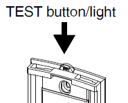
When the ground fault protection mechanism trips, the TEST light is On (red). To reset the ground fault protection, switch the thermostat to Standby and back to On. The TEST light will
go off. Supplied Parts
- One (1) power base
- Two (2) mounting screws
- Four (4) solderless connectors for copper wires
- One (1) flat-tip screwdriver
Installing the Power Base
- Turn off the power to the heating system at the service panel in order to avoid any risk of electrical shock.
- Connect the wires using solderless connectors for copper wires:

- Insert the floor sensor cable through one of the two openings on the base and connect the sensor wires to terminals 1 and 2 (no polarity).
- The sensor cable must pass outside the electrical box and follow the wall down to the floor.
- Position the sensor cable such that it does not come in contact with the floor heating wires. The sensor must be centered between two-floor heating wires for best
temperature control. - Do NOT staple the sensor head (the plastic end) to the floor. Doing so might damage the sensor. Any damages might not be noticeable during testing but can become apparent several days later.

- If you wish to connect a remote control device, insert the wires (use 18- to 22-gauge flexible wires) through one of the two openings on the base and connect them to terminals 2 and 3 (no polarity). If your thermostat has the Vacation Mode, the mode can be activated from an Aube telephone controller (CT240 or CT241) or any other remote control device equipped with a normally open (NO) dry contact. For more information on this mode, see the thermostat’s user guide.
- Push the excess length of the high-voltage wires back inside the electrical box.
- Secure the power base to the electrical box using the provided screws.
Installing the Control Module (faceplate)
- Verify the settings of the configuration switches (if any) on the back of the faceplate (see user guide).
- Install the control module (faceplate) on the power base (see user guide).
- Apply power to the heating system. Verify the installation by making sure that the heating system can be turned on and turned off by increasing and decreasing the setpoint.
- Test the ground fault protection
Testing the Ground Fault Protection
To ensure that ground fault protection is always in working order, test it once the thermostat is installed, and every month thereafter

- Increase the setpoint temperature above the measured temperature to activate the heating system.
- Press the TEST button.
- If the TEST light does NOT come on, the test has failed. Cut power to the heating system at the main electrical panel, have an electrician verify the installation and, if necessary, replace the thermostat.
- If the TEST light comes on, continue the test.
Technical Specifications
|
Supply |
Maximum Load (resistive only) |
Wiring |
|
| Current | Power | ||
| 120 VAC, 50/60Hz | 15 A | 1800 W | 4 wires, double pole |
| 240 VAC, 50/60Hz | 15 A | 3600 W | 4 wires, double pole |
| Model | Ground Fault Protection | Current Leakage Limit |
| GA | Ground Fault Circuit Interrupter (GFCI), class A | 5 mA |
| GB | Equipment Ground Fault Protection Device (EGFPD) | 15 mA |
Heating cycle length: 15 minutes
Operating temperature: 0°C to 50°C (32°F to 122°F)
Storage temperature: -20 °C to 50 °C (-4 °F to 120 °F)
Size (H • W • D): 124 x 70 x 23 mm (4.89 x 2.76 x 0.91 in.)
Warranty
Honeywell warrants this product, excluding the battery, to be free from defects in the workmanship or materials, under normal use and service, for one (1) year from the date of purchase by the consumer. If at any time during the warranty period, the product is determined to be defective or malfunctions, Honeywell shall repair or replace it (at Honeywell’s option).
If the product is defective,
(i) return it, with a bill of sale or other dated proof of purchase, to the place from which you purchased it, or
(ii) contact Honeywell. Honeywell will determine whether the product should be returned, or whether a replacement product can be sent to you.
This warranty does not cover removal or reinstallation costs. This warranty shall not apply if it is shown by Honeywell that the defect or malfunction was caused by damage that occurred
while the product was in the possession of a consumer. Honeywell’s sole responsibility shall be to repair or replace the product within the terms stated above. HONEYWELL SHALL NOT BE LIABLE FOR ANY LOSS OR DAMAGE OF ANY KIND, INCLUDING ANY INCIDENTAL OR CONSEQUENTIAL DAMAGES, RESULTING, DIRECTLY OR INDIRECTLY, FROM ANY BREACH OF ANY WARRANTY, EXPRESS OR IMPLIED, OR ANY OTHER FAILURE OF THIS PRODUCT. Some provinces, states, or regions do not allow the exclusion or limitation of incidental or consequential damages, so this limitation may not apply to you.
THIS WARRANTY IS THE ONLY EXPRESS WARRANTY HONEYWELL MAKES ON THIS PRODUCT. THE DURATION OF ANY IMPLIED WARRANTIES, INCLUDING THE WARRANTIES OF MERCHANTABILITY AND FITNESS FOR A PARTICULAR PURPOSE, IS HEREBY LIMITED TO THE ONE-YEAR DURATION OF THIS WARRANTY. Some provinces,
states or regions do not allow limitations on how long an implied warranty lasts, so the above limitation may not apply to you. This warranty gives you specific legal rights, and you may have other rights which vary from one province, state, or region to another. If you have any questions about the product, contact us at:
705 Montrichard Avenue
Saint-Jean-sur-Richelieu, Quebec
J2X 5K8
Canada Tel: 1-800-831-2823
E-mail: [email protected]
Automation and Control Solutions
Honeywell International Inc.
1985 Douglas Drive North
Golden Valley, MN 55422
customer.honeywell.com
By using this Honeywell literature, you agree that Honeywell will have no liability for any damages arising out of your use or modification to, the literature. You will defend and indemnify Honeywell, its affiliates, and its subsidiaries, from and against any liability, cost, or damages, including attorneys’ fees, arising out of, or resulting from, any modification to the literature by you.
Reference
Download Manual:
HONEYWELL PB112C-GA SMART THERMOSTAT INSTALLATION GUIDE
![]()

Leave a Reply