
Honeywell Home ERM5220R Equipment Remote Module

CAUTION
Read these installation instructions completely and follow them carefully.
Installation must be performed by a qualified service technician and must comply with local codes.
Disconnect power to all relevant devices before installing or servicing the ERM.
Failure to connect the device according to these instructions may result in damage to the device, the controls, and/or personal injury.
FEATURES
- Wireless RedLINK™ communication between condensing unit/compressor or boiler and thermostat.
- Eliminates the need to run additional wires to your outdoor condenser, multistage compressor, heat pump or dual fuel applications, or if original wiring has been damaged, or equipment has been relocated.
- Suitable for outdoor use.
- Temperature sensor terminals for outdoor temp sensors or indoor freeze protection.
- LEDs for easy installation checkout.
- May reduce damage to homes since wiring/drilling is eliminated.

SPECIFICATIONS
- Operating Ambient Temperature Range:
- Compressor: -40 to +155 ºF (-40 to +68 ºC)
- Boiler: 30 to +130 ºF (-1 to +54 ºC)
- Operating Relative Humidity Range: 0 – 99 %Electrical: 24 VAC, 50/60 Hz.
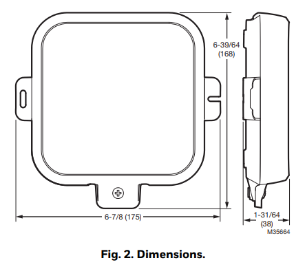
- Dimensions: 175 mm x 168 mm x 38 mm
- Wireless capability via RedLINK™ technology.
- Frequency: 902 – 928 MHZ (This is a “jumping frequency.” It jumps within the bands to reduce interference from other RF devices). Certified under the Federal Communication Commission (FCC) part 15.247.
- Cover screw: #10-24 UNC 3/8 Phillips pan head machine screw.
FCC REGULATIONS
§ 15.19 (A)(3)
This device complies with part 15 of the FCC Rules. Operation is subject to the following two conditions:
- This device may not cause harmful interference, and
- this device must accept any interference received, including interference that may cause undesired operation.
FCC WARNING
§ 15.21 (USA ONLY)
Changes or modifications not expressly approved by the party responsible for compliance could void the user’s authority to operate the equipment.
IC REGULATIONS
RSS-GEN
This device complies with Industry Canada’s licence-exempt RSSs. Operation is subject to the following two conditions:
- This device may not cause interference; and
- This device must accept any interference, including interference that may cause undesired operation of the device.
COMPATIBLE PRODUCTS
NOTE: The ERM5220R may only be used with the thermostats listed below. Look for this image on these products.
If you no longer have the thermostat or EIM packaging, verify thermostat model and manu-facture date are compatible with ERM. The date code of thermostat (and EIM, if used) must be 1546 or above (more recent). Compatible models of thermostat and EIM are listed in Tables 1 and 2. If your thermostat pre-dates ERM compatibility, see the info on Older Mod-els, below.
Table 1. ERM (equipment remote module) and kits including the ERM.
| ERM5220R1018 | Equipment Remote Module (ERM) |
| YERM5220R8321 | Kit with THM5220R1018 ERM and RedLINK-enabled TH8321R1001 VisionPRO thermostat |
| YERM5220RVPEIM | Kit with THM5220R1018 ERM (Equipment Remote Module), RedLINK-enabled TH8321R1001 VisionPRO thermostat and THM5421R1021 EIM (Equipment Interface Module) |
Table 2. Compatible models.
| VisionPRO RedLINK thermostats numbers | Prestige thermostat and thermostat kit numbers | EIM and EIM kit numbers |
| TH8110R1008* Thermostat | THX9421R5021* Thermostat | THM5421R1021* EIM |
| TH8320R1003* Thermostat | YTHX9421R5085* Thermostat + EIM + Delta-T sensors | |
| TH8321R1001* Thermostat | YTHX9421R5101* Thermostat + EIM + Wireless outdoor sensor + Delta-T sensors | YTHM5421R1010* EIM +
Delta-T sensors |
Note: Date code of thermostat (and EIM if used) needs to be 1546 or more recent (larger number).
Older Models
If the EIM/thermostat date code is smaller (older) than 1546:
- 2.0 or later versions of Prestige IAQ and RedLINK Vision-PRO thermostats can be used if you update the software on the thermostat.
- The software update page is https://thermostatsetup.com
- This page has updates for both Prestige IAQ and RedLINK VisionPRO. Prestige is updated via USB stick; VisionPRO is updated via microSD card.
- Prestige 1.0 models can not be updated.
- The EIM (if used) can not be updated and must be replaced.
Table 3. Other accessories.
| Model | Note |
| C7189U1005 | 10K ohm indoor sensor used as a backup on boiler applications.
If the stat fails for more than 30 minutes, it will maintain the system at 55 °F in heating. |
| C7089U1006 | 10K ohm outdoor sensor used with outdoor unit ERM5220R installations to display outdoor temperature at thermostat. |
| C7089R1013 | Wireless outdoor sensor |
| THM6000R7001 | RedLINK Internet Gateway (RIG) |
| REM5000R1001 | Portable comfort control |
NOTES:
- Only two ERMs can be enrolled in a system at one time – one in Boiler mode and one in Compressor mode.
- ERM is not supported by systems using a forced air zone panel, even if the thermostat is wired to the zone panel or linked to an EIM. (See the FAQ on page 27 for more on this).
- For Boiler applications, the thermostat must be configured for radiant heat.
- ERM will not support series 20 operation in boiler applications unless a relay is used (page 12). When configured for radiant heat the Y relay shall be off at all times.
- Prestige IAQ always requires a THM5421R EIM. The ERM can be used in conjunction with the EIM for forced air systems. The ERM would not be used with a Prestige IAQ on heat only systems without fan.

TERMINAL DESIGNATIONS FOR COMPRESSOR
Fig. 4. Terminal Designations for Compressor.
THE “D” TERMINAL OPERATES AS AN INPUT FOR DEFROST. ACTIVE INPUT ON “D” TERMINAL AT ERM WILL TELL THE THERMOSTAT TO POWER THE AUX (OR AUX 1) TERMINAL AT THE SUBBASE OR EIM. IF
“D” TO AUX IS NOT DESIRED, DO NOT CONNECT “D” TERMINAL TO THE ERM5220R IS CONFIGURED FOR USE WITH A COMPRESSOR. M36110
TERMINAL DESIGNATIONS FOR BOILER
Fig. 5. Terminal Designations for Boiler.
ERM WILL NOT SUPPORT SERIES 20 OPERATION UNLESS A RELAY IS ADDED (SEE FIGURE 14). WHEN CONFIGURED TO A BOILER, THE Y RELAY SHALL BE DE-ENERGIZED AT ALL TIMES.
Installation Checklist
MATERIALS SUPPLIED:
- ERM5220R
- Wall Anchors (x2) and Mounting Screws (x2)
- Extra Cover Screw (optional)
- Installation Instructions (33-00135EFS)
TOOLS NEEDED (NOT SUPPLIED):
- Drill
- Nut Driver Attachment for Drill
- Wire Stripper
- Small Flathead Screwdriver
- Phillips Screwdriver
- 120/240 V to 24 V Transformer (Furnace or Air-handler transformer can be used if 2 wires are available to outdoor unit)
Mounting ERM
- Use two screws and wall anchors to attach the ERM to the exterior wall near the compressor. The location should be at least 3 feet above ground and oriented with the two wire exits facing downward. See Figs. 6 and 7.
- Attach cover and secure with bottom screw (Fig. 8).


INSTALLATION
IMPORTANT
- The ERM is not compatible with forced air zone boards (see the FAQ on page 27 for details).
- To ensure that the ERM will receive a wireless signal at the desired installation location:
- Do not mount the ERM in a metal box. This would impede the RedLINK wireless signal.
- If your location has metal siding, the ERM’s signal may be affected. If there is no communication or poor signal strength, consider a different location.
- If there is a lot of concrete materials between the ERM and host (thermostat or EIM), the ERM’s signal may be affected. If there is no communication or poor signal strength, consider a different location.
- A Prestige (with EIM) or VisionPRO (with or without EIM) will only allow one of the following configurations:
- Enrolled with a single boiler configured ERM;
- Enrolled with a single compressor configured ERM;
- Enrolled with a single boiler configured ERM and enrolled with a single compressor configured ERM.
Wiring
- Make sure power to compressor/boiler is off.
- Remove the front cover by loosening the cover screw and lifting up from the bottom of the ERM.
- Remove 3 to 4 inches of the cable’s outer sheathing, then remove 3/8 to 1/2 inch of insulation from each wire.
- See Figures 10–15 for R to J jumper setting and wiring.

WIRING DIAGRAMS
Fig. 10. Compressor for conventional application.
- WIRE TRANSFORMER PRIMARY TO APPROPRIATE 120, 208, OR 240 VOLTAGE POWER SUPPLY AT OUTDOOR UNIT. TRANSFORMER NOT NECESSARY IF THERE ARE TWO WIRES AVAILABLE FROM R AND C ON INDOOR UNIT TO R AND C ON ERM. FOLLOW TRANSFORMER INSTALL GUIDE FOR WIRING OF TRANSFORMER PRIMARY.
- WIRE TRANSFORMER LOW VOLTAGE SECONDARY (R AND C) TO ERM5220R AS SHOWN.
- VEFIFY TRANSFORMER IS SIZED CORRECTLY TO HANDLE THE LOAD OF THE OUTDOOR UNIT (Y AND Y2).
- ADD A JUMPER WIRE FROM J TO R.
- Y2 IS NOT USED ON SINGLE STAGE EQUIPMENT.
- OUTDOOR SENSOR IS OPTIONAL. IF USED ON THIS APPLICATION IT ALLOWS THE OUTDOOR TEMPERATURE READING TO BE DISPLAYED ON THE THERMOSTAT. ALTERNATELY THE C7089R1013 WIRELESS OUTDOOR SENSOR CAN BE USED.
- IF A COMPATIBLE TH8000 SERIES RedLINK THERMOSTAT IS USED, AND THE THERMOSTAT IS ALSO WIRELESS TO THE INDOOR UNIT, AN EIM (EQUIPMENT INTERFACE MODULE) IS
- REQUIRED IN ADDITION TO THE ERM (EQUIPMENT REMOTE MODULE). THE COMPATIBLE PRESTIGE IAQ THERMOSTAT ALWAYS NEEDS TO BE PAIRED WITH AN EIM. M36120

Fig. 11. Heatpump.
- WIRE TRANSFORMER PRIMARY TO APPROPRIATE 120, 208, OR 240 VOLTAGE POWER SUPPLY AT OUTDOOR UNIT. TRANSFORMER NOT NECESSARY IF THERE ARE TWO WIRES AVAILABLE FROM R AND C ON INDOOR UNIT TO R AND C ON ERM. FOLLOW TRANSFORMER INSTALL GUIDE FOR WIRING OF TRANSFORMER PRIMARY.
- WIRE TRANSFORMER LOW VOLTAGE SECONDARY (R AND C) TO ERM5220R AS SHOWN.
- VEFIFY TRANSFORMER IS SIZED CORRECTLY TO HANDLE THE LOAD OF THE OUTDOOR UNIT (Y AND Y2).
- ADD A JUMPER WIRE FROM J TO R.
- Y2 IS NOT USED ON SINGLE STAGE EQUIPMENT.
- RHEEM AND RUUD HEATPUMPS USE B INSTEAD OF O.
- DEFROST WIRE CONNECTS TO D AT ERM52220R. CHECK WITH HEATPUMP LITEATURE TO SEE HOW THEY LABEL THIS TERMINAL. THE “D” TERMINAL OPERATES AS AN INPUT FOR
- DEFROST. ACTIVE INPUT ON “D” TERMINAL AT ERM WILL COMMUNICATE WITH THERMOSTAT TO POWER THE AUX OF (AUX1) TERMINAL AT THE THERMOSTAT SUBBASE OR EIM. IF “D”
- TO AUX IS NOT DESIRED, DO NOT CONNECT “D” TERMINAL TO THE ERM5220R. THIS FEATURE IS ONLY ACTIVE WHEN THE ERM5220R IS CONFIGURED FOR USE WITH A COMPRESSOR.
- IF THE HEATPUMP DOES NOT HAVE A CONNECTION FOR A COMPRESSOR MONITOR, DO NOT CONNECT L.
- OUTDOOR SENSOR IS OPTIONAL ON ELECTRIC BACKUP APPLICATIONS. FOR DUAL FUEL, THE OUTDOOR SENSOR IS REQUIRED. ALTERNATELY THE C7089R1013 WIRELESS OUTDOOR SENSOR CAN BE USED.
- THE AUXILIARY/EMERGENCY HEAT TERMINAL LABELING VARIES BY AIR-HANDLER OEM.
- IF A COMPATIBLE TH8000 SERIES RedLINK THERMOSTAT IS USED, AND THAT THERMOSTAT IS ALSO WIRELESS TO THE INDOOR UNIT, AN EIM (EQUIPMENT INTERFACE MODULE) IS
- REQUIRED IN ADDITION TO THE ERM (EQUIPMENT REMOTE MODULE). THE COMPATIBLE PRESTIGE IAQ THERMOSTAT ALWAYS NEEDS TO BE PAIRED WITH AN EIM.

Fig. 12. Boiler with a single zone.
- WIRE TRANSFORMER PRIMARY TO APPROPRIATE 120, 208, OR 240 VOLTAGE POWER SUPPLY. FOLLOW TRANSFORMER INSTALL GUIDE FOR WIRING OF TRANSFORMER PRIMARY.
- WIRE TRANSFORMER LOW VOLTAGE SECONDARY (R AND C) TO ERM5220R AS SHOWN.
- REMOVE JUMPER WIRE FROM J TO R.
- INDOOR SENSOR IS OPTIONAL. IF USED ON THIS APPLICATION IT ALLOWS THE ERM TO DO FREEZE PROTECTION CONTROL IF COMMUNICATION IS LOST WITH THE THERMOSTAT.
- IF A COMPATIBLE TH8000 SERIES RedLINK THERMOSTAT IS USED, AND THAT THERMOSTAT IS ALSO WIRELESS TO THE INDOOR UNIT, AN EIM
(EQUIPMENT INTERFACE MODULE) IS REQUIRED IN ADDITION TO THE ERM (EQUIPMENT REMOTE MODULE). THE COMPATIBLE PRESTIGE IAQ THERMOSTAT ALWAYS NEEDS TO BE - PAIRED WITH AN EIM, EVEN ON A HEAT ONLY SYSTEM. BECAUSE OF THIS, IT WOULD BE UNUSUAL TO USE THE ERM5220R WITH A PRESTIGE IAQ THERMOSTAT ON A HOT WATER HEAT ONLY SYSTEM WITHOUT FAN.
- FOR HYDROAIR (HOT WATER COIL) APPLICATIONS, MAKE SURE TO CONFIGURE THE THERMOSTAT TO ENERGIZE THE FAN IN HEAT MODE.

WIRING AT THERMOSTAT IF CUSTOMER ALSO HAS FORCED AIR COOLING OR A HYDRO-AIR APPLICATION (NOT REQUIRED ON HEAT ONLY APPLICATIONS)
Fig. 13. Power-open/spring closed zone valve.
- WIRE TRANSFORMER PRIMARY TO APPROPRIATE 120, 208, OR 240 VOLTAGE POWER SUPPLY. FOLLOW TRANSFORMER INSTALL GUIDE FOR WIRING OF TRANSFORMER PRIMARY.
- WIRE TRANSFORMER LOW VOLTAGE SECONDARY (R AND C) TO ERM5220R AS SHOWN.
- REMOVE JUMPER WIRE FROM J TO R. ADD JUMPER FROM R TO ONE OF THE T TERMINALS ON ERM AS SHOWN.
- INDOOR SENSOR IS OPTIONAL. IF USED ON THIS APPLICATION IT ALLOWS THE ERM TO DO FREEZE PROTECTION CONTROL IF COMMUNICATION IS LOST WITH THE THERMOSTAT.
- IF A COMPATIBLE TH8000 SERIES RedLINK THERMOSTAT IS USED, AND THAT THERMOSTAT IS ALSO WIRELESS TO THE INDOOR UNIT, AN EIM
(EQUIPMENT INTERFACE MODULE) IS REQUIRED IN ADDITION TO THE ERM (EQUIPMENT REMOTE MODULE). THE COMPATIBLE PRESTIGE IAQ THERMOSTAT ALWAYS NEEDS TO BE - PAIRED WITH AN EIM, EVEN ON A HEAT ONLY SYSTEM. BECAUSE OF THIS, IT WOULD BE UNUSUAL TO USE THE ERM5220R WITH A PRESTIGE IAQ THERMOSTAT ON A HOT WATER HEAT ONLY SYSTEM WITHOUT FAN.
- FOR HYDROAIR (HOT WATER COIL) APPLICATIONS, MAKE SURE TO CONFIGURE THE THERMOSTAT TO ENERGIZE THE FAN IN HEAT MODE.

Fig. 14. Series 20, Power-open/power closed zone valve.
- WIRE TRANSFORMER PRIMARY TO APPROPRIATE 120, 208, OR 240 VOLTAGE POWER SUPPLY. FOLLOW TRANSFORMER INSTALL GUIDE FOR WIRING OF TRANSFORMER PRIMARY.
- WIRE TRANSFORMER LOW VOLTAGE SECONDARY (R AND C) TO ERM5220R AS SHOWN.
- REMOVE JUMPER WIRE FROM J TO R. ADD JUMPER FROM R TO ONE OF THE T TERMINALS ON ERM AS SHOWN.
- ERM DOES NOT USE Y FOR HOT WATER VALVE. R8222B1067 OR EQUIVALENT ISOLATION RELAY REQUIRED.
- INDOOR SENSOR IS OPTIONAL. IF USED ON THIS APPLICATION IT ALLOWS THE ERM TO DO FREEZE PROTECTION CONTROL IF COMMUNICATION IS LOST WITH THE THERMOSTAT.
- IF A COMPATIBLE TH8000 SERIES RedLINK THERMOSTAT IS USED, AND THAT THERMOSTAT IS ALSO WIRELESS TO THE INDOOR UNIT, AN EIM
(EQUIPMENT INTERFACE MODULE) IS REQUIRED IN ADDITION TO THE ERM (EQUIPMENT REMOTE MODULE). THE COMPATIBLE PRESTIGE IAQ THERMOSTAT ALWAYS NEEDS TO BE - PAIRED WITH AN EIM, EVEN ON A HEAT ONLY SYSTEM. BECAUSE OF THIS, IT WOULD BE UNUSUAL TO USE THE ERM5220R WITH A PRESTIGE IAQ THERMOSTAT ON A HOT WATER HEAT ONLY SYSTEM WITHOUT FAN.
- FOR HYDROAIR (HOT WATER COIL) APPLICATIONS, MAKE SURE TO CONFIGURE THE THERMOSTAT TO ENERGIZE THE FAN IN HEAT MODE.

Fig. 15. Hot water relay panel.
- WIRE TRANSFORMER PRIMARY TO APPROPRIATE 120, 208, OR 240 VOLTAGE POWER SUPPLY. FOLLOW TRANSFORMER INSTALL GUIDE FOR WIRING OF TRANSFORMER PRIMARY.
- WIRE TRANSFORMER LOW VOLTAGE SECONDARY (R AND C) TO ERM5220R AS SHOWN.
- REMOVE JUMPER WIRE FROM J TO R.
- INDOOR SENSOR IS OPTIONAL. IF USED ON THIS APPLICATION IT ALLOWS THE ERM TO DO FREEZE PROTECTION CONTROL IF COMMUNICATION IS LOST WITH THE THERMOSTAT.
- IF A COMPATIBLE TH8000 SERIES RedLINK THERMOSTAT IS USED, AND THAT THERMOSTAT IS ALSO WIRELESS TO THE INDOOR UNIT, AN EIM
(EQUIPMENT INTERFACE MODULE) IS REQUIRED IN ADDITION TO THE ERM (EQUIPMENT REMOTE MODULE). THE COMPATIBLE PRESTIGE IAQ THERMOSTAT ALWAYS NEEDS TO BE - PAIRED WITH AN EIM, EVEN ON A HEAT ONLY SYSTEM. BECAUSE OF THIS, IT WOULD BE UNUSUAL TO USE THE ERM5220R WITH A PRESTIGE IAQ THERMOSTAT ON A HOT WATER HEAT ONLY SYSTEM WITHOUT FAN.
- FOR HYDROAIR (HOT WATER COIL) APPLICATIONS, MAKE SURE TO CONFIGURE THE THERMOSTAT TO ENERGIZE THE FAN IN HEAT MODE.
LINKING ERM5220R TO A NEW COMPATIBLE THERMOSTAT.
NOTE: If thermostat setup had already been done but ERM5220R had not been linked to the thermostat, see page 16.
- Verify thermostat model and manufacture date are compatible with ERM (should say compatible with ERM on packaging). Information about compatible models of thermostat and EIM is on page 3.
- Turn on power. Once power is connected, the “Compressor” (or “Boiler”) LED should illuminate green.

- When the thermostat is powered it will prompt you to select whether the system is residential or commercial. After setting residential or commercial and choosing the thermostat name, the display shows the below screen (setup 110).
- The ERM5220R does not work on a forced air system zoned with dampers. Select “no” if the system is either a single zone forced air unit, or a zoned hot water system. A zoned hot water system would require a separate ERM5220R for each wireless thermostat).
NOTE: For questions about why the ERM cannot be used on a forced air zone system, see the FAQ section. - Equip. module (EIM) THM5421R is separate from remote module ERM. See notes below for when an EIM is used.
- If not using an Equipment Interface Module, select “no” at the thermostat with arrow button, then press “next”. Skip to step 10.
- If using an Equipment Interface Module, select “yes” at the thermostat with arrow button, then press “next”. Proceed with step 6.

EQUIPMENT INTERFACE MODULE (EIM) THM5421R. WHEN IS IT USED?- The Prestige IAQ always requires an EIM even if it is hot water heat only. For this reason it would be unusual to use the ERM5220R with a Prestige IAQ on a hot water heat only application.
- The TH8110R, TH8320R, and TH8321R models do not require an EIM for hot water heat only applications with no fan control.
- The TH8110R, TH8320R, and TH8321R models do not require an EIM if the furnace/air-handler is wired to the thermostat subbase.
- The TH8110R, TH8320R, and TH8321R models do require an EIM if the thermostat controls cooling or fan, and there are not wires from the thermostat to the furnace/air-handler.
- Thermostat display says “Press Connect at Equipment Module”. Go to the Equipment Interface Module and press the connect button.
- Verify the connected LED starts flashing.
- Go back to the thermostat and press “Next”.
- Thermostat display should show “Thermostat connected”. Press “Next”.
- Select “Yes” to connect RedLINK accessories (Including ERM5220R Equipment Remote Module).
- The thermostat display says “Press Connect on New Accessories”.

- Press/release the “Connect” button on the ERM5220R. After releasing the button, the Connected LED should flash green and then turn solid green.

- Back at thermostat, display will indicate that the Equipment Remote Module has been added. Press “Next” to continue with the installer setup options.
- Go through the rest of the ISU settings. For boiler systems make sure to designate “Radiant Heat” for Heating System Type (ISU 200) in your thermostat.

- If you do not have an EIM, you are done. If you are using an EIM, (this is a separate item from the ERM) go to the EIM. If the connected LED is still flashing, press/release the connect button on EIM. If the connect LED was already solid green you are done.
LINKING ERM5220R TO AN EXISTING COMPATIBLE THERMOSTAT.
Verify thermostat model and manufacture date are compatible with ERM. Information about compatible models of thermostat and EIM is on page 3.
- Turn on power. Once power is connected, the “Compressor” (or “Boiler”) LED should illuminate green.
- Reset procedure at ERM: (Skip to step 3 if ERM is new)
If you want to unlink the ERM from any RedLINK devices it is currently paired with, hold down the “Connect” button on the ERM for at least 15 seconds. The “Connection” LED should appear red for a few seconds and go out. This indicates the unit is reset. - Existing installation of thermostat
This is for when the installer setup options have already been saved but the ERM5220R was not added at that time. Note: If thermostat setup has not already been done, use the instructions for new thermostats on page 14. - Install the R to J jumper when using ERM on outdoor unit. Remove the R to J jumper when using ERM on boiler.
- Verify thermostat is configured correctly for system. Designate “Radiant Heat” for Heating System Type (ISU 200) at your thermostat if ERM controls boiler.
- At thermostat, press “Menu”. Scroll down to “Equipment status”. Press select. Then scroll down until date code is highlighted. Write this down. Then press “Done”.
- Scroll down until “Installer Options” is shown. Then press “Select”.

- Enter the date code and press “Done”.
- Scroll down until “Wireless Manager” is highlighted. Then press “Select”.

- If the thermostat had previously been linked to an ERM that is being replaced, proceed to step 10.
- If you are not replacing an existing ERM with a new one, skip to step 12.
- Scroll down until “Remove Device” is highlighted. Press “Select”.
- Scroll down until “Equip Rem. Module” is selected. And press “Select”. Display says “Remove Equip. Rem. Module?” Select “Yes”.

- Scroll up or down until “Add Device” is highlighted in screen. Then press “Select”.
- The thermostat display says “Press Connect on New Accessories”.

- Press/release the “Connect” button on the ERM5220R. After releasing the button, the connected” LED should flash green and then turn solid green.

- Back at thermostat, display will indicate that the Equipment Remote Module has been added. Press “Done”.

Checkout
- Verify power is on to the compressor or boiler as well as your RedLINK thermostat and ERM.
- If testing ERM for heat, switch the thermostat to heat and raise the set-point above room temperature. If testing ERM for cooling, switch thermostat to cool and lower set-point below room temperature.
- The thermostat may say “waiting for equipment” for up to 5 minutes when controlling the outdoor unit. This is a safety feature for the outdoor unit to prevent short cycling.
- When the thermostat shows “heat on” or “cool on” go to ERM and verify the boiler or outdoor unit is running. If the LED above Y is flashing, the ERM is doing a compressor lockout. The ERM will do this when first powered up, even if the compressor lockout has been removed from the thermostat..
- If outdoor temperature sensor is used (only when ERM is controlling the outdoor unit), check thermostat to see the out-door temperature display is active and accurate.
- Be sure to set the thermostat to the desired settings when checkout is complete.

OPERATION
ERM USED FOR OUTDOOR UNIT: CALL FOR COOLING
- Thermostat is set to cool or auto mode. Cool set-point is below room temperature.
- Thermostat will show “cool on” in the display. (the display may show “waiting for equipment” if the minimum com-pressor off delay has not expired prior to the call for cool. Typically this is up to 5 minutes).
- If thermostat is set for either conventional system or heatpump with heat changeover, the LED will be lit green over the Y at the ERM. The switch will close from J to Y at the ERM. If an EIM is wired to the air-handler/furnace, the EIM will close a switch from Rc to Y and Rc to G. If no EIM is used, the thermostat will close from Rc to Y and Rc to G at the subbase.
- If thermostat is set for heatpump with cool changeover, the LEDs will be lit green over the Y and O/B at the ERM. The switch will close from J to Y and J to O/B at the ERM. If an EIM is wired to the air-handler/furnace, the EIM will close a switch from Rc to Y, Rc to G, and Rh to O/B. If no EIM is used, the thermostat will close from Rc to Y, Rc to G, and R to O/B at the subbase.
- If the thermostat is configured for 2 stage compressor, then in addition to the operation listed above, with a call for stage 2 cooling the LED over Y2 will be lit green on ERM. If an EIM is wired to the air-handler or furnace, the EIM will close an additional switch from Rc to Y2. If no EIM is used, the thermostat will close an additional switch from Rc to Y2 at the subbase. The Y2 at EIM or subbase is not connected to some furnace and air-handler models.
ERM USED FOR OUTDOOR UNIT: CALL FOR HEATING (HEATPUMP ONLY)
- Thermostat is set to heat or auto mode. Heat set-point is above room temperature.
- Thermostat will show “Heat on” in the display. (the display may show “waiting for equipment” if the minimum com-pressor off delay has not expired prior to the call for heat. Typically this is up to 5 minutes).
- If thermostat is set for heatpump with cool changeover valve, the LED will be lit green over the Y at the ERM. The switch will close from J to Y at the ERM. If an EIM is wired to the air-handler/furnace, the EIM will close a switch from Rc to Y and Rc to G. If no EIM is used, the thermostat will close from Rc to Y and Rc to G at the subbase.
- If thermostat is set for heatpump with heat changeover valve, the LEDs will be lit green over the Y and O/B at the ERM. The switch will close from J to Y and J to O/B at the ERM. If an EIM is wired to the air-handler/furnace, the EIM will close a switch from Rc to Y, Rc to G, and Rh to O/B. If no EIM is used, the thermostat will close from Rc to Y, Rc to G, and R to O/B at the subbase.
- If the thermostat is configured for 2 stage compressor, then in addition to the operation listed above, with a call for stage 2 heating the LED over Y2 will be lit green on ERM. If an EIM is wired to the air-handler/furnace, the EIM will close an additional switch from Rc Y2. If no EIM is used, the thermostat will close an additional switch from Rc to Y2 at the subbase.
ERM USED FOR BOILER: CALL FOR HEATING
- Thermostat is set to heat or auto mode. Heat set-point is above room temperature.
- Thermostat will show “Heat on” in the display.
- The LED will be lit green over the second T at the ERM. (The LED over the first T does not light when ERM is used for a boiler). The dry contact switch will close from T to T at the ERM*. If an EIM is also used, the EIM will close a switch from Rh to W. If no EIM is used, the thermostat will close from R to W at the subbase. If the thermostat is set to energize the fan in heat (hydro-coil) the thermostat or EIM will also close from Rc to G.
- you may not be able to measure continuity across this closed switch. See Fig. 18 for troubleshooting heat.
HEATPUMP GOES INTO DEFROST
NOTE: This feature is intended for heatpumps with electric auxiliary heat only. If the thermostat is set for dual fuel, the D terminal on ERM should not be used, and would have no function other than to light the D LED when the defrost board is engaged.
- The heatpump controls when defrost is engaged, not the zone panel.
- The thermostat subbase or EIM closes from Rc to Y and Rc to G at air-handler with a call for heat. This operation does not change when the defrost terminal is energized by the ERM.
- If the heat pump defrost board sends the signal for defrost on the D wire, ERM5220 shows the D LED solid green.
- Assuming the thermostat is calling for heat, ERM is still closing from the J to the Y. The LED for Y should remain lit.
- ERM does not change operation of changeover valve when heatpump is in defrost.
- ERM communicates to thermostat or EIM when the defrost terminal (D) is energized. Thermostat subbase or EIM (if used) closes additional switch from R (Rh) to AUX to run the electric heat strips. There is not any indication on the thermostat that it is energizing the AUX contact when the ERM is driving this operation. The thermostat might show “auxiliary heat on” in the display, but that is due to a demand for auxiliary heat from the thermostat, independent of what the ERM is doing.
COMPRESSOR FAULT MONITOR ENERGIZES L ON ERM
- The heatpump compressor fault monitor energizes the L terminal on the ERM. The LED above L is lit green on ERM5220R.
- ERM communicates fault to thermostat. Thermostat display shows 1 active alert and says to “press here for more info”. When the customer presses “here”, the thermostat says “heat pump needs service”.
This does not change the outputs of the thermostat or ERM.
TROUBLESHOOTING
| Symptom | Possible Cause | Action |
| Connected LED is red | Loss of communication to thermostat. Check thermostat display to see if it is blank or shows error codes. If there had been a loss of power to the thermostat it could take up to 6 minutes before communication is restored. | If thermostat display is blank, check power at thermostat subbase. R and C on THX9421R models. Rc and C at TH8000R series models. If display is normal, reset the ERM and then link it to the thermostat. This process is on page 16. |
| Connected LED is off | If no LEDs are lit, see “No LEDs are on” below. If compressor or boiler is lit, this indicates the ERM is not linked to a compatible RedLINK thermostat. | See the appropriate linkup process on pages 14 or 16. |
| No LEDs are on | Insufficient power to R and C at ERM. | Verify nominal voltage (24 VAC) at R and C on ERM. Verify wires are stripped back and making good connections. |
| Wrong LED lit (boiler or compressor) | Either jumper is installed incorrectly or ERM had been previously linked for boiler or compressor and needs to be reset. If previously linked connect LED is typically red or green rather than unlit. | Verify the R to J jumper is set correctly (remove jumper for boiler, add jumper for compressor). Reset the ERM by pressing/holding the “Connect” button for 30 seconds. |
| No outdoor temperature shown on the thermostat display. | If configured for outdoor sensor, the thermostat should show an outdoor temperature reading or error code about the outdoor sensor not being connected. If a wired sensor is used but there is an issue it may show two dashes (see below). If neither an outdoor temperature reading nor an error code is shown, verify the thermostat configuration settings. | |
| The thermostat shows dashes “–” for outdoor temperature | NOTE: The thermostat can display outdoor temperature in one of four ways. Find the way you have connected the outdoor sensor from the list below and follow the instructions).
1. Wired outdoor sensor connected to ERM and ERM configured for compressor application. You cannot wire an outdoor sensor to the ERM if it is set for boiler. (see R to J jumper on wiring section). If an outdoor sensor is wired to the ERM, verify the compressor and connected LEDs are solid green at the ERM. If so, disconnect the wires and take a resistance reading at the ends of the wires. Check the outdoor sensor chart (Table 4 on page 28). 2. An outdoor sensor is wired to the EIM. If an EIM is used, and the sensor is wired to EIM, verify the thermostat is configured for the outdoor sensor to the terminals it connects to. Disconnect the wires and take a resistance reading at the ends of the wires. Check the outdoor sensor chart (Table 4 on page 28). 3. A wired outdoor sensor connected to the sensor terminals on one of the TH8000R series com- patible thermostats. (Note: This should only be done if an EIM is not used. The EIM is different than the ERM. If an EIM is used, the outdoor sensor must wire to the EIM or ERM). Disconnect the wires and take a resistance reading at the ends of the wires. Check the outdoor sensor chart (Table 4 on page 28). 4. A C7089R wireless outdoor sensor linked to the thermostat. See if the outdoor sensor shows up in the thermostat installer options under wireless manager-connected devices. If not, go to “add device” and then press the button on the outdoor sensor and verify the thermostat display indi- cates it has been added. |
|
| Outdoor temperature reading is too high | Verify outdoor temperature sensor is not in direct sunlight. See the outdoor sensor install instructions on page 29. | |
| Emergency backup control doesn’t function correctly. | If a C7189U1005 (or equivalent) 10K ohm indoor sensor is wired to the S1 terminals on the ERM AND the ERM is configured for boiler control, the ERM uses that sensor to maintain an indoor temperature of 55 °F in heating in case there is loss of communication from the thermostat to ERM that exceeds 30 minutes.
1. Verify the sensor is wired to ERM and wire connections are good. 2. Verify that the sensor is not wired in series to parallel to any other thermostat, module or device. 3. Remove wires from ERM and ohm out the wires. Compare that reading with outdoor sensor chart, Table 4 on page 28 (indoor and outdoor sensor resistance chart is the same). Temperature must be below 55 °F for ERM to run boiler in emergency backup mode. 4. Verify that the loss of communication between the thermostat and ERM has exceeded 30 minutes. 5. If temp at sensor has been below 55 °F for longer than 30 minutes, see if the LED above the O/B/T is green. If yes, boiler should be running. If no, verify boiler LED is solid green and con- nection LED is solid green for over 30 minutes. |
|


FREQUENTLY ASKED QUESTIONS
- Q: Do I need an EIM (equipment Interface module) when using an ERM (Equipment remote module)?
A: It depends-- If you are using a Prestige IAQ with ERM, the EIM is always required. For a heat-only application, use the EIM only (no ERM).
- If using one of the 8000 RedLINK models (TH8110R, TH8320R, TH8321R) with a boiler for heat only, you can use an ERM and do not need an EIM. (Thermostat needs 24 volts at Rc and C when EIM is not used).
- If using one of the 8000 RedLINK models (TH8110R, TH8320R, TH8321R) for outdoor unit AND you have wires from air-handler to thermostat subbase you do not need an EIM. (Thermostat needs
- 24 volts at Rc and C when EIM is not used)
- If you need to be wireless to outdoor unit AND indoor unit you need an EIM.
- Q: How many ERMs can I link to a single thermostat?
A: up to 2 ERMs can be linked per compatible thermostat. One for boiler and one for outdoor unit. - Q: Can I link more than one thermostat to the same ERM?
A: No. - Q: How do I verify compatibility?
A: See page 3. - Q: What happens if communication is lost between ERM and thermostat?
A: If there is still power at the thermostat and it has not been removed from the wall, the thermostat will indicate that signal was lost.- If controlling a boiler with ERM and there is an indoor sensor wired to ERM, 30 minutes after communication is lost “Freeze control” is enabled, the ERM controls to 55 from the sensor reading.
- If controlling a boiler with ERM and there is not a sensor linked to ERM the boiler will not run, regardless of temperature until communication is restored.
- If controlling an outdoor unit the outdoor unit will not run until communication is restored.
- Q: Do I need to wire a sensor to the S1 terminals on ERM?
A: No. If you do not use the indoor sensor when controlling a boiler, you would not have the “Freeze control” (described in answer 5). If you do not use a wired sensor for the outdoor unit, the thermostat will not display outdoor temperature unless the wireless outdoor sensor is used instead. Sensor are listed in Table 3 on page 3. - Q: Are the terminals on the thermostat subbase or EIM (equipment Interface module) also energized when using the ERM?
A: Yes.- If linked to EIM and ERM, (and ERM set for boiler) they both get energized with a call for heat. So we close from Rh to W at EIM and we close from T to T at ERM.
- When ERM is used for outdoor unit (ERM closes from R to Y and EIM closes from Rc to Y and G).
- With the TH8110R, TH8320R, or TH8321R series stat, if there is no EIM used, subbase of the stat closes the switches in addition to ERM.
- EIM is always required with PIAQ (THX9421R) even when used with ERM to boiler for heat only. So an ERM would not make sense for those applications. Use EIM instead.
- Q: Can I use the ERM with a forced air zone panel?
A: No. The ERM is designed to link to a single thermostat (or thermostat + EIM). It cannot link to a zone panel. Do not attempt a work-around (such as linking a separate ERM to each thermostat and wiring them in parallel). If this were done we would have one or more of the following issues:- We eliminate the purge delay on the panel. This is a minimum off time at the end of each cool cycle before it attempts to run cooling again. If each thermostat is by-passing the zone panel and directly controlling outdoor unit we could cycle off from one zone, and then 5 seconds later a different zone could call for cooling.
- The zone panel has logic to prevent heat and cooling from running at the same time. If each thermostat is by-passing the zone panel and directly controlling outdoor unit we could be running the heat and AC at the same time.
- For heat-pump operation, when configured for cool changeover, the ERM keeps the O/B changeover energized continually after the cooling call until it sees a heat call. When configured for heat changeover, the ERM keeps the O/B changeover energized continually after the heat call until it sees a cooling call. So there could be a thermostat trying to call for heat, but the cool changeover is being energized by a different ERM or vise-versa.
C7089U1006 WIRED OUTDOOR SENSOR
Resistance scale
(Used with C7089U outdoor sensor and C7189U indoor sensor)
Table 4. Sensor Resistance at Outdoor Temperature.
| Outdoor Temperature |
Ohms of Resistance |
|
| °F | °C | |
| -40 | -40 | 195652 |
| -38.2 | -39 | 184917 |
| -36.4 | -38 | 174845 |
| -34.6 | -37 | 165391 |
| -32.8 | -36 | 156512 |
| -31 | -35 | 148171 |
| -29.2 | -34 | 140330 |
| -27.4 | -33 | 132957 |
| -25.6 | -32 | 126021 |
| -23.8 | -31 | 119493 |
| -22 | -30 | 113347 |
| -20 | -28.9 | 106926 |
| -18 | -27.8 | 100923 |
| -16 | -26.7 | 95310 |
| -14 | -25.6 | 90058 |
| -12 | -24.4 | 85124 |
| -10 | -23.3 | 80485 |
| -8 | -22.2 | 76137 |
| -6 | -21.1 | 72060 |
| -4 | -20.0 | 68237 |
| -2 | -18.9 | 64631 |
| 0 | -17.8 | 61246 |
| 2 | -16.7 | 58066 |
| 4 | -15.6 | 55077 |
| 6 | -14.4 | 53358 |
| 8 | -13.3 | 49598 |
| 10 | -12.2 | 47092 |
| 12 | -11.1 | 44732 |
| 14 | -10.0 | 42506 |
| 16 | -8.9 | 40394 |
| 18 | -7.8 | 38400 |
| 20 | -6.7 | 36519 |
| 22 | -5.6 | 34743 |
| 24 | -4.4 | 33063 |
| 26 | -3.3 | 31475 |
| 28 | -2.2 | 29975 |
| 30 | -1.1 | 28558 |
| 32 | 0.0 | 27219 |
| 34 | 1.1 | 25949 |
| 36 | 2.2 | 24749 |
| Outdoor Temperature |
Ohms of Resistance |
|
| °F | °C | |
| 38 | 3.3 | 23613 |
| 40 | 4.4 | 22537 |
| 42 | 5.6 | 21516 |
| 44 | 6.7 | 20546 |
| 46 | 7.8 | 19626 |
| 48 | 8.9 | 18754 |
| 50 | 10.0 | 17926 |
| 52 | 11.1 | 17136 |
| 54 | 12.2 | 16387 |
| 56 | 13.3 | 15675 |
| 58 | 14.4 | 14999 |
| 60 | 15.6 | 14356 |
| 62 | 16.7 | 13743 |
| 64 | 17.8 | 13161 |
| 66 | 18.9 | 12607 |
| 68 | 20.0 | 12081 |
| 70 | 21.1 | 11578 |
| 72 | 22.2 | 11100 |
| 74 | 23.3 | 10644 |
| 76 | 24.4 | 10210 |
| 78 | 25.6 | 9795 |
| 80 | 26.7 | 9398 |
| 82 | 27.8 | 9020 |
| 84 | 28.9 | 8659 |
| 86 | 30.0 | 8315 |
| 88 | 31.1 | 7986 |
| 90 | 32.2 | 7672 |
| 92 | 33.3 | 7372 |
| 94 | 34.4 | 7086 |
| 96 | 35.6 | 6813 |
| 98 | 36.7 | 6551 |
| 100 | 37.8 | 6301 |
| 102 | 38.9 | 6062 |
| 104 | 40.0 | 5834 |
| 106 | 41.1 | 5614 |
| 108 | 42.2 | 5404 |
| 110 | 43.3 | 5203 |
| 112 | 44.4 | 5010 |
| 114 | 45.6 | 4826 |
| 116 | 46.7 | 4649 |
| 118 | 47.8 | 4479 |
| 120 | 48.9 | 4317 |
| 122 | 50 | 4160 |
| 123.8 | 51 | 4026 |
| 125.6 | 52 | 3896 |
| 127.4 | 53 | 3771 |
CAUTION Electrical Interference (Noise) Hazard.
Can cause erratic system operation.Keep wiring at least one foot away from large inductive loads such as motors, line starters, lighting ballasts and large power distribution panels.
Use shielded cable to reduce interference when rerouting is not possible.
IMPORTANT Erratic temperature readings from a sensor can occur as a result of any of the wiring practices described below. Avoid these practices to assure correct operation. Use shielded cable to reduce interference if rerouting of sensor wiring is not possible.
- Be sure wires have a cable separate from the thermostat cable.
- Do not route temperature sensor wiring with building power wiring, next to control contactors or near light dimming circuits, electric motors or welding equipment.
- Avoid poor wiring connections.
- Avoid intermittent or missing building earth ground.
Wiring the C7089U outdoor sensor
In most cases, shielded cable is not required and 18 gauge copper wire can be used. Wire the sensor to the two S1 terminals on the ERM5220R
NOTE: Never wire the same sensor in parallel to two devices. If there are two units with separate ERM5220R modules, each would need a separate sensor.
Location and Mounting
Mount the sensor where:
- People cannot tamper with settings.
- There is good air circulation.
- It can measure true outdoor ambient temperature.
- The surface is flat.
- The wire distance between C7089 and thermostat is less than 200 feet.
Do not mount the sensor:
- In direct sunlight.
- Where hot or cold air blows on the sensor.
- Discharge line from an outdoor compressor unit, vent or fan causes inaccurate temperature readings.
- Where snow, ice or debris can cover it.
Use the following steps to mount the sensor:
- Remove the sensor from the mounting clip.
- Mark the area on the location selected for mounting the sensor mounting clip.
- Mount the clip.
5 YEAR WARRANTY
Resideo warrants this product to be free from defects in workmanship or materials, under normal use and service, for a period of five (5) years from the date of first purchase by the original purchaser. If at any time during the warranty period the product is determined to be defective due to workmanship or materials, Resideo shall repair or replace it (at Resideo’s option).
If the product is defective,
- return it, with a bill of sale or other dated proof of purchase, to the place from which you purchased it; or
- call Resideo Customer Care at 1-800-468-1502. Customer Care will make the determination whether the product should be returned to the following address: Resideo Return Goods, 1985 Douglas Dr. N., Golden Valley, MN 55422, or whether a replacement product can be sent to you.
This warranty does not cover removal or reinstallation costs. This warranty shall not apply if it is shown by Resideo that the defect was caused by damage that occurred while the product was in the possession of a consumer. Resideo’s sole responsibility shall be to repair or replace the product within the terms stated above. RESIDEO SHALL NOT BE LIABLE FOR ANY LOSS OR DAMAGE OF ANY KIND, INCLUDING ANY INCIDENTAL OR CONSEQUENTIAL DAMAGES RESULTING, DIRECTLY OR INDIRECTLY, FROM ANY BREACH OF ANY WARRANTY, EXPRESS OR IMPLIED, OR ANY OTHER FAILURE OF THIS PRODUCT. Some states do not allow the exclusion or limitation of incidental or consequential damages, so this limitation may not apply to you.
THIS WARRANTY IS THE ONLY EXPRESS WARRANTY RESIDEO MAKES ON THIS PRODUCT. THE DURATION OF ANY IMPLIED WARRANTIES, INCLUDING THE WARRANTIES OF MERCHANTABILITY AND FITNESS FOR A PARTICULAR PURPOSE, IS HEREBY LIMITED TO THE FIVE YEAR DURATION OF THIS WARRANTY. Some states do not allow limitations on how long an implied warranty lasts, so the above limitation may not apply to you. This warranty gives you specific legal rights, and you may have other rights which vary from state to state. If you have any questions concerning this warranty, please write Resideo Customer Care, 1985 Douglas Dr, Golden Valley, MN 55422 or call 1-800-468-1502.
Resideo Technologies, Inc.
1985 Douglas Drive North, Golden Valley, MN 55422
1-800-468-1502
33-00205—02 M.S. Rev. 01-22 | Printed in United States
© 2020 Resideo Technologies, Inc. All rights reserved.
The Honeywell Home trademark is used under license from Honeywell International, Inc. This product is manufactured by Resideo Technologies, Inc. and its affiliates.
www.resideo.com
Download Manual
Honeywell Home ERM5220R Equipment Remote Module User Guide
Other Manuals:
Honeywell Home ERM5220R Equipment Remote Module Installation Guide