Honeywell Home RCHT8600 Z-wave Programmable Thermostat

Included in your box

Tools you will need Tools you may need

Removing your old thermostat
- Turn the power OFF.
To protect yourself and your equipment, Turn off the power at the breaker box or switch that controls your heating/cooling system.
- Check that your system is off. Change the temperature on your old thermostat. If you don’t hear the system turn on within 5 minutes, the power is off.
Note: If you have a digital thermostat that has a blank display, Skip this step - Remove the old thermostat’s faceplate. On most thermostats, you can take off the faceplate by grasping and gently pulling. Some thermostats may have screws, buttons, or clasps.
Do not remove any wires from your thermostat at this time!
- Make sure there are no 120/240V wires. Do you have thick black wires with wire nuts? Is your thermostat 120V or higher? If you answered yes to either of these questions, you have a line voltage system and the thermostat will not work. If you are unsure visit: honeywellhome.com/support
- Take a picture of how your wiring looks right now. Be sure to include the letters next to the terminals where the wires are inserted. This will be a helpful reference when wiring your
thermostat.
Tip: If the color of your wires has faded or if 2 terminals have the same wire color, use the wire labels provided in the package to label each wire.
- Record if you have wires in the following terminals. Do not include jumpers as a part of your count. The thermostat does not need jumpers

- Write down the color of the wires. Check mark the wires that are connected to terminals. Next to the check mark, write down the color of the wire. Do not include jumpers as a part of your count. Check all that apply (Not all will apply):

- The RCHT8600 thermostat does not support U terminals. If there are wires in terminals that are not listed, you will need additional wiring support. Visit honeywellhome.com/support to find out if the thermostat will work for you.
Disconnect the wires and remove the old wall plate.
Use a screwdriver to release wires from terminals. Then, use a wire label to identify each wire as it’s disconnected. The letter on the wire label should match the letter on the terminal.
Tip: To prevent wires from falling back into the wall, wrap the wires around a pencil. Installing your RCHT8600 thermostat
- Bundle and insert wires through the UWP. Pull open the UWP and insert the bundle of wires through the back of the UWP. Make sure at least 1/4-inch of each wire is exposed for easy insertion into the wire terminals.

- Insert the wall anchors. It is recommended that you use the wall anchors included in the box to mount your thermostat. You can use the UWP to mark where you want to place the wall anchors.
- Level the wall plate.
- Mark the location of the wall anchors using a pencil.
- Drill the holes.
- Insert wall anchors.
- Make sure anchors are flush with the wall.
Tip: If your box contains red anchors, drill 7/32” holes. If your box contains yellow anchors, drill 3/16” holes.
- Set the R-switch position and insert the R-wire or wires. Set the R-switch up or down based on your wiring notes in Step 7. Insert wires into the inner holes of the terminals on the UWP. The tabs will stay down once the wire is inserted.

Power options

NOTES:
- The RCHT8600 series Z-Wave thermostat works in battery mode or normal power mode based on its power source. The Z-Wave power mode can only be changed when the thermostat is NOT included in a Z-Wave network. You can check the power mode in the thermostat menu under MENU/DEVICE INFO.
- If a C wire is not used or present, the thermostat must be powered by batteries. The thermostat will operate in LSS mode (power-save, sleep mode) to help conserve battery life after it has been included in a Z-Wave network. The Z-Wave radio supports beaming. It allows other devices in the network to wake up the Z-Wave thermostat, accept commands and then go back to sleep.
- If you need the thermostat to operate in AOS mode (always listening mode) to act as a signal repeater and to increase network reliability, you need to power the thermostat by 24 VAC. The AOS mode information is provided via Node Information Frame (NIF).
Wiring UWP
Push down on the tabs to put the wires into the inner holes of their corresponding terminals on the UWP (one wire per terminal) until they are firmly in place. Gently tug on the wires to verify they are secure. If you need to release the wires again, push down the terminal tabs on the sides of the UWP.

Turn your power ON. Turn on the power at the breaker box or switch that controls the heating/ cooling system.

Return to the thermostat Return to the thermostat. Confirm the screen shows START SETUP. If your thermostat does not show START SETUP, please contact Customer Care at 1-800-468-1502. Start setup. Touch START SETUP to begin Navigate and edit setup options. Use the ![]() or
or ![]() to navigate through all the setup options. To see a list of all setup options, go to page 10-13.
to navigate through all the setup options. To see a list of all setup options, go to page 10-13.
To edit an option, touch Edit or touch text area. The value is now blinking. Use or to select the correct value. Touch Done or touch text area once the correct value is selected Finish setup.
Touch until you see FINISH SETUP. Touch Select or touch text area.
Set time and date. Set daylight saving time if you are in an area that follows daylight saving time. Set date, clock format, and time on the next screens. 18 Your thermostat is now setup. Refer to page 8 for more information about basic operation.

Key features

The screen will wake up by pressing the center area of the displayed temperature. If powered by 24 VAC, the screen stays lit for 45 seconds after you complete changes. If powered by battery only, the screen stays lit for 8 seconds. Brightness of an inactive backlight can be adjusted in the thermostat MENU only if the thermostat is powered by 24 VAC.
Thermostat features
The RCHT8600 series Z-Wave Programmable Thermostat is a Z-Wave Plus certified thermostat designed to work with any Z-Wave compliant controller or gateway for easy programming and automation to deliver energy savings and comfort at the same time. The thermostat can be operated in any Z-Wave network together with other Z-Wave certified devices from other manufacturers. All nonbattery operated Z-Wave devices (nodes) within the network will act as repeaters regardless of manufacturer to increase reliability of the network. When integrated
with the app that controls your Z-Wave controller, it lets you program and control your home’s HVAC system as well as control other Z-Wave devices connected to the same Z-Wave controller. Flexible scheduling: The thermostat is fully programmable when not included into a Z-Wave network.
Each day can be programmed for different heating and cooling settings in 4 unique periods (Wake, Away, Home, Sleep). The thermostat scheduling options available differ depending on whether the thermostat is included or excluded from Z-Wave network, on capability of your Z-Wave controller and app to program thermostat. Displays ambient air temperature, % relative indoor humidity and reports HVAC system status: You can display actual temperature or % relative humidity, or to see whether your cooling / heating system is running. Auto change from heat to cool: When Auto mode is selected, the RCHT8600 series Z-Wave thermostat can automatically determine whether your home needs heating or cooling to reach the desired temperature at the right time. Smart Alerts: The RCHT8600 series Z-Wave thermostat can alert you when your HVAC system is not working properly and can remind you for things like when to change your furnace filter. Smart Response Technology: The RCHT8600 series Z-Wave thermostat learns your heating and cooling cycle times to make sure the system delivers the
temperature you want, when you want it. (Available only if the local thermostat schedule is enabled.) Power method: Designed for battery operation (3 x AA batteries) or for 24 VAC power operation (via a “C” or common wire).
System Setup options
To access all system options in the table below, press and hold MENU for 5 seconds. Touch ![]() or
or ![]() to scroll through the list.
to scroll through the list.
| Number | Description | Options (factory default in bold) |
|
120 |
Scheduling Options |
0 = Non-Programmable
1 = 1-Week Programmable 2 = 5-2 Programmable 3 = 5-1-1 Programmable 4 = 7-Day Programmable Note: You can change default MO-FR, SA-SU schedule here. To edit periods during days, temperature setpoints, or to turn Schedule On/Off, touch MENU and go to SCHEDULE. |
| 125 | Temperature Indication Scale | 0 = Fahrenheit
1 = Celsius |
|
130 |
Outdoor Temp |
No, Wired
Note: An outdoor temperature is required to set the following ISUs: ISU 355 Balance point (Compressor Lockout), ISU 356 Aux Heat Lockout. Use a wired outdoor sensor connected to the “S” terminals on the UWP and set this ISU to Wired. (See “Wiring—heat pump” on page 21.) |
|
200 |
Heating System Type |
1 = Conventional Forced Air Heat
2 = Heat Pump 3 = Radiant Heat (Boiler) 5 = None (Cool Only) Note: This option selects the basic system type your thermostat will control. |
| Conventional Forced Air Heat:
1 = Standard Efficiency Gas Forced Air 2 = High Efficiency Gas Forced Air 3 = Oil Forced Air 4 = Electric Forced Air 5 = Hot Water Fan Coil |
||
| 205 | Heating Equipment Type | Heat Pump:
7 = Air to Air Heat Pump 8 = Geothermal |
| Radiant Heat:
9 = Hot Water Radiant Heat 12 = Steam Note: This option selects the equipment type your thermostat will control. Note: This feature is NOT displayed if feature 200 is set to Cool Only. |
||
|
218 |
Reversing Valve O/B |
0 = O (O/B in Cool)
1 = B (O/B in Heat) Note: This option is only displayed if the Heat Pump configured. Select whether reversing valve O/B should energize in cool or in heat. |
|
220 |
Cool Stages / Compressor Stages 200=Conv / 200=HP |
0, 1, 2
Note: Select how many Cool or Compressor stages of your equipment the thermostat will control. Maximum of 2 Cool/Compressor Stages. Set value to 0 if you do not have Cool Stage/ Compressor Stage. |
|
221 |
Heat Stages / Backup Heat Stages Heat Stages |
Heat Stages: 1, 2
Backup Heat Stages: 0, 1 Note: Select how many Heat or Aux/E stages of your equipment the thermostat will control. Maximum of 2 Heat Stages for conventional systems. Maximum of 1 Aux/E stage for systems with more than 1 heating equipment type. Set value to 0 if you do not have Heat Stage/Backup Heat Stage. |
|
230 |
Fan Control |
1 = Equipment
2 = Thermostat Note: This ISU is only displayed if ISU 205 is set to Electric Forced Air or Fan Coil. |
|
253 |
Aux/E Control |
Both Aux/E, Either Aux/E
Note: Set “EITHER AUX/E” if you want to setup and control of Auxiliary and Emergency heating separately . This ISU is only displayed if ISU 200 is set to Heat Pump AND if ISU 221 Aux/E stages = 1. |
|
255 |
Aux Heat Type |
Electric, Gas/Oil (or Fossil Forced Air)
Note: This ISU is displayed only if ISU 200 is set to heat pump AND if ISU 221 Aux/E heat stages = 1. |
| Number | Description | Options (factory default in bold) |
|
256 |
EM Heat Type |
Electric, Gas/Oil (or Fossil Forced Air)
Note: This ISU is displayed only if ISU 200 is set to Heat Pump AND if ISU 221 Aux/E heat stages = 1 AND if ISU 253 is set to run AUX/E heat separately. |
|
260 |
Fossil Kit Control |
Thermostat, External (Fossil Fuel Kit Controls Backup Heat)
Note: This ISU is displayed only if ISU 200 is set to Heat Pump AND if ISU 221 Aux/E heat stages = 1, AND if ISU 256 is set to Gas/Oil. |
|
300 |
System Changeover |
0 = Manual
1 = Automatic Note: Thermostat can automatically control both heating and cooling to maintain the desired indoor temperature. To be able to select “automatic” system mode on thermostat home screen, turn this feature ON. Turn OFF if you want to control heating or cooling manually. |
|
303 |
Auto Differential |
0 °F to 5 °F or 0.0 °C to 2.5 °C
Note: Differential is the minimum number of degrees rise or fall required during off cycle to switch from the last active mode (heat or cool) to the opposite mode when the thermostat is in auto-changeover. Differential is NOT deadband. The deadband temperature between when heating (or cooling) cycles on and cycles off to maintain setpoint is not adjustable. This thermostat uses an algorithm that fixes deadband at 0 °F. |
|
305 |
High Cool Stage Finish |
Yes, No Note: This ISU is only displayed when the thermostat is set to 2 cool stages. When set to YES, this feature keeps the higher stage of the cooling equipment running until the desired setpoint is reached. |
|
306 |
High Heat Stage Finish |
Yes, No Note: This ISU is only displayed when the thermostat is set to 2 or more heat stages. When set to YES, this feature keeps the higher stage of the heating equipment running until the desired setpoint is reached. |
|
340 |
Aux Heat Droop |
0 = Comfort; 2 °F to 15 °F from setpoint (in 1 °F increments) or 1.0 °C to 7.5 °C from setpoint (in 0.5 °C increments)
Note: Aux heat droop can be set on heat pump systems with an auxiliary heat stage. The Comfort setting is NOT available for Dual Fuel systems. Default setting is 0 °F (Comfort) for Electric while 2 °F for Gas/Oil. The indoor temperature must drop to the selected droop setting before the thermostat will turn Aux Heat on. For example, if Aux Heat is set to 2 °F (1.0 °C), the indoor temperature must be 2 ° F (1.0 ° C) away from the setpoint before Aux Heat turns on. When set to Comfort, the thermostat will use Aux Heat as needed to keep the indoor temperature within 1 °F (0.5 ° C) degree of the setpoint. |
|
350 |
Up Stage Timer Aux Heat |
Off, 30, 45, 60, 75, 90 minutes
2, 3, 4, 5, 6, 8, 10, 12, 14, 16 hours Note: The Auxiliary Heat Upstage Timer starts when the highest stage of the previous heating equipment type turns on. Auxiliary heat will be used (if needed) when the timer expires. This ISU is only displayed when ISU 340 (AUX Heat Droop) is set to 2 °F or higher. |
|
355 |
Balance Point (Compressor Lockout) |
Off, 5 °F to 60 °F (in 5 °F increments) or 15.0 °C to 15.5 °C (in 2.5 °C or 3.0 °C increments) Note: Compressor Lockout requires an outdoor temperature. Set Compressor Lockout to the temperature below which it is inefficient to run the heat pump. When outside temperature is below this setting, thermostat will lockout the heat pump and run Aux Heat only. This ISU is only displayed if ISU 130 = Wired, ISU 200 is set to Heat Pump, ISU 221 Aux/E stages = 1. Default
is 40 °F if ISU 205 Heating Equipment is Air to Air Heat Pump and ISU 255 Aux Heat Type is Gas/Oil. Default is Off if ISU 205 Heating Equipment is Air to Air Heat Pump and ISU 255 Aux Heat Type is Electric. Default is Off if ISU 205 Heating Equipment is Geothermal. Compressor Lockout is optional for any type of heat pump (Air to Air Heat Pump, Geothermal Heat Pump). |
|
356 |
Aux Heat Lock Out (Aux Heat Outdoor Lockout) |
Off, 5 °F to 65 °F (in 5 °F increments) or
-15.0 °C to 18.5 °C (in 2.5 °C or 3.0 °C increments) Note: Aux Heat Lockout requires an outdoor temperature. Set Aux Heat Lockout to optimize energy bills and to not allow to run the more expensive Aux Heat source above certain outdoor temperature limit. This ISU is only displayed if ISU 130 = Wired, ISU 200 is set to Heat Pump, ISU 221 Aux/E stages = 1. |
|
365 |
Cool 1 CPH (Cooling cycle rate stage 1) |
1 – 6 CPH (3 CPH)
Note: This ISU is only displayed when Cool /Compressor Stages is set to 1 or more stages. Cycle rate limits the maximum number of times the system can cycle in a 1 hour period measured at a 50% load. For example, when set to 3 CPH, at a 50% load, the most the system will cycle is 3 times per hour (10 minutes on, 10 minutes off). The system cycles less often when load conditions are less than or greater than a 50% load. |
| Number | Description | Options (factory default in bold) |
| 366 | Cool 2 CPH (Cooling cycle rate stage 2) | 1 – 6 CPH (3 CPH)
Note: This ISU is only displayed when Cool /Compressor Stages is set to 2. |
|
370 |
Heat 1 CPH (Heating cycle rate stage 1) |
1 – 12 CPH
Note: This ISU is only displayed when Heat Stages is set to 1 stage or more stages. Cycle rate limits the maximum number of times the system can cycle in a 1 hour period measured at a 50% load. For example, when set to 3 CPH, at a 50% load, the most the system will cycle is 3 times per hour (10 minutes on, 10 minutes off). The system cycles less often when load conditions are less than or greater than a 50% load. The recommended (default) cycle rate settings are below for each heating equipment type: Standard Efficiency Gas Forced Air = 5 CPH; High Efficiency Gas Forced Air = 3 CPH; Oil Forced Air = 5 CPH; Electric Forced Air = 9 CPH; Fan Coil = 3 CPH; Hot Water Radiant Heat = 3 CPH; Steam = 1 CPH. |
|
371 |
Heat 2 CPH (Heating cycle rate stage 2) |
1 – 12 CPH
Note: This ISU is only displayed when Heat Stages is set to 2 stages. The recommended (default) cycle rate settings are below for each heating equipment type: Standard Efficiency Gas Forced Air = 5 CPH; High Efficiency Gas Forced Air = 3 CPH; Oil Forced Air = 5 CPH; Electric Forced Air = 9 CPH; Fan Coil = 3 CPH; Hot Water Radiant Heat = 3 CPH; Steam = 1 CPH. |
|
375 |
Aux Heat CPH (Heating cycle rate Auxiliary Heat) |
1 – 12 CPH
Note: This ISU is only displayed when ISU 200 = Heat Pump and ISU 221=1. It is only displayed when Auxiliary Heat is configured. The recommended cycle rate settings are below for each heating equipment type: Standard Efficiency Gas Forced Air = 5 CPH; High Efficiency Gas Forced Air = 3 CPH; Oil Forced Air = 5 CPH; Electric Forced Air = 9 CPH. |
|
378 |
EM Heat CPH (Heating cycle rate Emergency Heat) |
1 – 12 CPH
Note: This ISU is only displayed when Emergency Heat is configured and ISU 253: Aux/E Terminal Control is set to control Aux and E heat Independently. The recommended cycle rate settings are below for each heating equipment type: Standard Efficiency Gas Forced Air = 5 CPH; High Efficiency Gas Forced Air = 3 CPH; Oil Forced Air = 5 CPH; Electric Forced Air = 9 CPH. |
|
387 |
Compressor Protection |
Off, 1 – 5 minutes
Note: The thermostat has a built in compressor protection (minimum off timer) that prevents the compressor from restarting too early after a shutdown. The minimum-off timer is activated after the compressor turns off. If there is a call during the minimum-off timer, the thermostat shows “Cool on” or “Heat On” (heat pump) status blinking on the thermostat home screen. This ISU is displayed if ISU 220 is set to at least 1 stage. |
|
390 |
Ext Fan Run Time in Cool |
Off, 30, 60, 90 seconds
2, 3, 4, 5, 6, 7, 8, 9, 10, 11, 12, 13, 14, 15 minutes Note: After the call for cooling ends, the thermostat keeps the fan on for the selected amount of time for increased efficiency. This may reintroduce humidity into the living space. This ISU is displayed if ISU 220 is set to at least 1 stage. |
|
391 |
Ext Fan Run Time in Heat |
Off, 30, 60, 90 seconds 2, 3, 4, 5, 6, 7, 8, 9, 10, 11, 12, 13, 14, 15 minutes Note: After the call for heating ends, the thermostat keeps the fan on for the selected amount of time for increased efficiency. This ISU is displayed if ISU 230 is set to Thermostat Controls Fan. |
|
425 |
Smart Response |
0 = No
1 = Yes Note: Smart Response is a comfort setting. Heat or Cooling equipment will turn on earlier, ensuring the indoor temperature will match the setpoint at the scheduled time. See page 22. |
|
430 |
Minimum Cool Temperature Setpoint |
50 °F to 99 °F (50 °F)
10.0 °C to 37.0 °C (10.0 °C) Note: The cool temperature cannot be set below this level. |
|
431 |
Maximum Heat Temperature Setpoint |
40 °F to 90 °F (90 °F)
4.5 °C to 32.0 °C (32.0 °C) Note: The heat temperature cannot be set above this level. |
|
435 |
Lock Screen |
None, Partial, Full
Unlocked: User has access to all thermostat settings. Partially Locked: User can modify only temperature settings. Fully Locked: User cannot modify any settings. Screen will be locked by default factory code and cannot be changed. This code is displayed for a short time, when you are about to lock the thermostat screen. Please note the code in safe place for future reference. |
| Number | Description | Options (factory default in bold) |
|
500 |
Indoor Sensor |
Yes, No
Note: Set this ISU when you want to wire a remote indoor sensor to the “S” terminals on the UWP. This ISU is only displayed if ISU 130 is set to NO wired outdoor sensor configured. |
|
515 |
Sensor type |
10k, 20k
Note: Choose resistance type of wired indoor sensor. This ISU is only displayed when indoor sensor is configured – ISU 500. |
|
520 |
Temperature Control |
Thermostat, Wired, Average
Note: This ISU is only displayed when indoor sensor is configured – ISU 500. You can choose what temperature source to be used or you can ask thermostat to use both thermostat and remote sensors for higher accuracy of measurement. |
| 702 | Air Filters | 0 – 1
Note: This ISU refers to the number of air filters in the system. |
|
711 |
Air Filter 1 Replacement Reminder |
0 = Off 10 = 45 Calendar Days
1 = 10 Run Time Days 11 = 60 Calendar Days 2 = 20 Run Time Days 12 = 75 Calendar Days 3 = 30 Run Time Days 13 = 3 Calendar Months 4 = 45 Run Time Days 14 = 4 Calendar Months 5 = 60 Run Time Days 15 = 5 Calendar Months 6 = 90 Run Time Days 16 = 6 Calendar Months 7 = 120 Run Time Days 17 = 9 Calendar Months 8 = 150 Run Time Days 18 = 12 Calendar Months 9 = 30 Calendar Days 19 = 15 Calendar Months
Note: Set a reminder for when to change your air filter. Choose either calendar or equipment run time-based reminder. |
|
712 |
Air Filter 2 Replacement Reminder | |
| 810 | Hum Pad Reminder | Off
6, 12 Calendar Months |
|
921 |
Dehum Filter Reminder |
Off
30, 60 Calendar Days 3 – 12 Calendar Months (in 1 month increments) |
| 1018 | Vent Filter Reminder | Off, 3, 6, 9, 12 months |
|
1100 |
UV Devices |
0 – 2
Note: Some systems may have two UV devices, one for the A-Coil and another for Air Treatment. A replacement reminder can be setup for each one separately. |
| 1105 | UV Bulb 1 Reminder | Off, 6, 12, 24 months |
| 1106 | UV Bulb 2 Reminder | Off, 6, 12, 24 months |
|
1401 |
Idle Brightness |
0= Off, 0 – 5
Note: Adjust brightness of an inactive backlight (idle screen) from default 0 (backlight off) to 5 (maximum brightness). Common wire required for settings 1-5. |
| 1410 | Clock Format | 12 hour, 24 hour |
|
1415 |
Daylight saving time |
0 = Off
1 = On Note: Set to Off in areas that do not follow Daylight Saving Time. |
|
1420 |
Temperature Offset |
0 = Off, -3 °F to 3 °F (in 1 °F increments) or
-1.5 °C to 1.5 °C (in 0.5 °C increments) Note: 0 °F – No difference in displayed temperature and the actual room temperature. The thermostat can display up to 3 °F (1.5 C) lower or higher than the actual measured temperature. |
|
1425 |
Humidity Display Offset |
0 = Off, -12% to 12% (in 1% increments)
Note: 0% – No difference in displayed and actual room % relative humidity. The thermostat can display up to 12% lower or higher than the actual measured % relative humidity. |
Z-Wave configuration parameters
If your gateway/hub/controller supports configuration function, you may remotely configure or change the default thermostat configuration parameters. For detailed table with all available Z-Wave configuration parameters search for RCHT8600 series Z-Wave Thermostat in the Z-Wave certified products section on http://Z-Wavealliance.org
Z-Wave setup

To add to include or remove to exclude the thermostat from Z-Wave network, go to thermostat MENU/Z-WAVE SETUP.
- Touch Select. You will be asked to set your primary controller to INCLUDE MODE. Please refer to the user manual of your Z-Wave controller.
- After inclusion procedure has been initiated on your Z-Wave controller, touch Select on the thermostat.
- If the inclusion procedure is successful, “INCLUDED”, the node ID, and the Z-Wave connected status icon appear on the screen. If the procedure fails, “FAILED TO INCLUDE”
appears on the screen. If this happens, position the thermostat closer to the Z-Wave controller and repeat the inclusion rocedure. - Your controller will indicate whether the thermostat was successfully added to its network. (Please refer to the user manual of your Z-Wave controller.)
NOTES: - Once the thermostat is included into the Z-Wave network, it assumes to be programmed from your Z-Wave controller and the program schedule on the thermostat is turned OFF by default. If the thermostat is not included into the Z-Wave network, then this thermostat will function as normal programmable thermostat. For more information, see “Scheduling options” on page 17.
- Before adding the thermostat to a Z-Wave network, check that it does not already belong to one. If the thermostat is included in Z-Wave network, it offers to exclude. If the thermostat is excluded from Z-Wave network, it offers to include. You can also check the status by viewing the Node ID located in the thermostat MENU/DEVICE INFO. An excluded thermostat should show zero for the Node ID (000).
- hether you are adding the thermostat for inclusion or removing for exclusion from Z-Wave network, first you have to initiate it on your Z-Wave controller. Please refer to the user manual of your Z-Wave controller.
- For other specific tasks, such as adding the thermostat to home automation scenes or groups, refer to the Z-Wave controller instructions.
- The RCHT8600 series Z-Wave thermostat works in the optional Z-Wave battery mode or normal power mode based on its power source. The Z-Wave power mode can only be changed when thermostat is NOT included in Z-Wave network. You can check the power mode in the thermostat menu under MENU/DEVICE INFO.
- If 24 VAC power source is not used or available, the thermostat must be powered by batteries. The thermostat will operate in LSS mode (power-save, sleep mode) to help conserve battery life after it has been included in a Z-Wave network. The Z-Wave radio supports beaming. It allows other devices in the network to wake up the Z-Wave thermostat, accept commands, and then go back to sleep.
- If you need the thermostat to operate AOS mode (always listening mode) to act as signal repeater and to increase network reliability, you need to ask your professional installer to power the thermostat by 24 VAC.
Z-Wave connection status
Z-Wave connection status is located in the upper-right Corner of the screen.

 Thermostat is included and connected to a Z-Wave network.
- Thermostat is excluded from a Z-Wave network.
- Thermostat is either included in a Z-Wave network but the Z-Wave signal is lost, or is included but AC power is lost (battery used as backup). In this case, Z-Wave radio is turned off to preserve battery life. AC power must be restored or you have to change the power mode. It can be done via excluding thermostat from Z-Wave network and including again in battery power mode where batteries are used as main power source. You can check the actual power mode in the thermostat MENU/DEVICE INFO.
System operation settings

- Press the Mode button to cycle to the next available System mode.

- Cycle through the modes until the required System mode is displayed and leave it to activate.
NOTE: Available System modes vary by model and system settings. System modes:- Auto: Thermostat selects heating or cooling as needed.
- Heat: Thermostat controls only the heating system.
- Cool: Thermostat controls only the cooling system.
- Em Heat (only for heat pumps with auxiliary heat): Thermostat controls Auxiliary Heat. Compressor is not used.
- Off: Heating and cooling system is off. Fan will still operate if fan is set to On or Circulate.
Fan operation settings
- Press the Fan button to cycle to the next available Fan mode.

- Cycle through the modes until the required Fan mode is displayed and leave it to activate.

NOTE: Available Fan modes vary with system settings.
Fan modes:- Auto: Fan runs only when the heating or cooling system is on.
- On: Fan is always on.
- Circ: Fan circulates randomly about 33% of the time.
Scheduling options
This thermostat may be configured to be programmable or non programmable. Thermostat schedule is an optional menu item. It will only show up in the thermostat menu if enabled in the Installer setup – advanced menu. It provides setting for local thermostat schedule control. Once the thermostat is included in to Z-Wave network, it assumes to be programmed from your Z-Wave controller and the program schedule on the thermostat is turned OFF by default. Use just the controller or associated app to program schedule (automation scenes) for the thermostat.
- Only Home and Away periods appear on the thermostat home screen.
- Home temperature setpoints are adjustable on the thermostat Home screen.
Common for all days. - Away mode is an Energy saving mode adjustable in the thermostat MENU/ AWAY SETTING. Common for all days. See table below with default, adjustable settings:
| Thermostat schedule is turned OFF, thermostat included in Z-Wave network | |||
| Period | Start Time | Heat | Cool |
| Away | N/A* | 62 ° | 85 ° |
| Home | N/A* | 72 ° | 78 ° |
Triggered by Z-Wave controller

Enabling thermostat schedule when thermostat is included in Z-Wave network (optional):
Z-Wave controllers from various manufacturers may or may not support the Z-Wave Thermostat General V2 Device class used by the RCHT8600 series Z-Wave Thermostat. If your controller does not support full thermostat device class functions, it may still be able to control basic Home/ Away (Energy Saving) modes of the thermostat through BASIC_SET commands (ON/OFF) used by the controller for other Z-Wave devices (eg. lighting devices). When only basic commands capable to receive from controller, you can enable the local thermostat schedule to differentiate between temperatures when you are away and when you are at home to differentiate between home and sleep temperatures.
- Home, Away and Sleep periods appear on the thermostat home
- Home and Sleep temperature and time settings are adjustable in the thermostat MENU/SCHEDULE.
- Away mode is an Energy saving mode adjustable in the thermostat MENU/ AWAY SETTING. Common for all
See table below with default 5+2 schedule (Mon-Fri; Sat-Sun), adjustable settings:
| Thermostat schedule is turned ON, thermostat included in Z-Wave network | |||||
| Period | Start Time | Heat (Mon-Fri) | Cool (Mon-Fri) | Heat (Sat-Sun) | Cool (Sat-Sun) |
| Away | N/A* | 62 ° | 85 ° | 62 ° | 85 ° |
| Home | 6:00 Am | 70 ° | 78 ° | 70 ° | 78 ° |
| Sleep | 10:00 Pm | 62 ° | 85 ° | 62 ° | 85 ° |
Triggered by Z-Wave controller

- If the Schedule menu on the thermostat does not appear, make sure that thermostat schedule is enabled. This setting is accessed from INSTALLER SETUP
ADVANCED MENU (see page 10), ISU 120 – Schedule type. Here you can also choose from pre-defined different thermostat program schedule types to be adjustable in the thermostat MENU/SCHEDULE.
Program schedule on the thermostat when not included in Z-Wave network (not operated by Z-Wave controller)
The RCHT8600 series Z-Wave thermostat will function as fully programmable thermostat when not operated by your controller. Each day can be programmed for different heating and cooling setpoints in 4 unique periods (Wake, Away, Home, Sleep) in the thermostat MENU/ SCHEDULE. Make sure that thermostat schedule is enabled in INSTALLER SETUP – ADVANCED (see page 10), ISU 120 – Schedule type.
| Thermostat schedule is turned ON, thermostat excluded from Z-Wave network | |||||
| Period | Start Time | Heat (Mon-Fri) | Cool (Mon-Fri) | Heat (Sat-Sun) | Cool (Sat-Sun) |
| Wake | 6:00 am | 70 ° | 78 ° | 70 ° | 78 ° |
| Away | 8:00 am | 62 ° | 85 ° | 62 ° | 85 ° |
| Home | 6:00 Pm | 70 ° | 78 ° | 70 ° | 78 ° |
| Sleep | 10:00 Pm | 62 ° | 85 ° | 62 ° | 85 ° |

- Wake, Away, Home, Sleep periods appear on the thermostat home
- Temperature setpoints for all four periods, different per day or group of days are adjustable in thermostat MENU/ SCHEDULE
Program schedule overrides
If the thermostat is included in Z-Wave network it typically follows the setting on your Z-Wave controller. If you adjust the temperature setting, it overrides the current setting until new state (eg. Home/Away) and/or the new temperature setting is received from Z-Wave controller. Setting of Hold until time and Permanent hold (see below) will not be available on the thermostat screen at this time. There are several scheduling options available for the thermostat. For more information, see “Scheduling options” on page 17. If the thermostat is not included in Z-Wave network and the thermostat is following local time based schedule only, you can set what time the new temperature setting will be held until or you can hold the new temperature setting permanently.
Program schedule override (temporary)

- Touch
 or
or  on the thermostat home screen to set your desired temperature. Hold Until will appear together with the time the hold will end.
 - To change when the hold will end, touch Hold Until and wait until the time starts blinking. Then, touch or to set when you want the hold to end. Touch Hold Until once more to confirm changes and return to the home screen. After the hold period ends, the thermostat will automatically return to the program schedule. If you want to cancel the hold, touch Hold Until and then touch Run Schedule.
Program schedule override (permanent)

- Touch or on the thermostat home screen to reach your desired temperature. Hold Until will appear together with the time you want the hold to end.
- Touch Hold Until. Permanent Hold will appear on screen. Touch Permanent Hold to hold this temperature until you manually change it. To end permanent hold and return to the
program schedule, touch Permanent Hold and then touch Run Schedule.
Wiring—conventional systems
Alternate wiring (conventional systems) If labels do not match terminals, connect wires as shown below (see notes, below).
NOTES:
- If you must connect both R and Rc wires, set the R Slider Tab to the down position (2 wires).
- If your old thermostat had both R and RH wires, set the R Slider Tab to the down position (2 wires). Then connect the R wire to the Rc terminal, and the RH wire to the R terminal.
- If your old thermostat had only 1 C or C1 wire, connect it to the C terminal. If your old thermostat had 2 C or C1 wires, wrap each separately with electrical tape and do not connect them.

Connect wires: heat pump
 Match each labeled wire with same letter on new thermostat.
- Insert the wires into the matching terminal.
NOTE: If you have difficulty inserting wires, you may have to press down the terminal push button next to the corresponding terminal. Labels don’t match? If labels do not match the letters on the thermostat, see “Alternate wiring (for heat pumps only)” below.
Alternate wiring (for heat pumps only)
NOTES:
- Keep R Slider Tab in the up position (1 wire).
- If your old thermostat had both V and VR wires, stop now and contact a qualified contractor for help.
- If your old thermostat had separate O and B wires, attach the B wire to the C terminal. If another wire is attached to the C terminal, stop now and contact a qualified contractor for help.
- If your old thermostat had Y1, W1 and W2 wires, stop now and contact a qualified contractor for help.

NOTE: Do NOT use W for heat pump applications. Auxiliary heat must wire to AUX or E.
Smart Response® Technology
This feature allows the thermostat to “learn” how long the furnace and air conditioner take to reach programmed temperature settings, so the temperature is reached at the time you set. For example: Set the Wake time to 6 am, and the temperature to 70°. The heat will come on before 6 am, so the temperature is 70° by the time you wake at 6. The message “Recovery” is displayed when the system is activated before a scheduled time period.
Battery replacement

Batteries are required to provide power when common wire is not used. Batteries are recommended to provide backup power if common wire is used. Install fresh batteries immediately when the low battery icon appears. The icon appears about two months before the batteries are depleted. Even if the low battery icon does not appear, you should replace batteries once a
year, or before leaving home for more than a month. If batteries are inserted within two minutes, the time and day will not have to be reset. All other settings are permanently stored in memory, and do not require battery power.
NOTE: When replacing batteries, alkaline batteries are recommended.
Enabling/disabling Smart Response
Over time, your RCHT8600 series Z-Wave thermostat will learn how long it takes your system to reach the desired temperature. It can then turn on your heating or cooling equipment
at the right time to make sure your home is comfortable by the time you expect. This feature is is available only if thermostat schedule is enabled in the thermostat Installer setup menu
and turned On. To disable it follow steps below:

- Touch Menu on the thermostat home screen.
- Touch the
 or
or arrows until you see RECOVERY, then touch Select.
 - Touch the or arrows to select RECOVERY ON or RECOVERY OFF, then touch Done to confirm. When Smart Response is active, you’ll see the recovery symbol in the upper-right corner of the thermostat screen.
Setting the time and date
NOTE: The date and time are automatically updated by the Z-wave control when enrolled.
Setting the time
- Touch Menu on the thermostat home screen.
- Touch the or arrows until you see CLOCK, then touch Select.
- Touch the or arrows until you see SET TIME, then touch Select.
- Press or to set the time (or press and hold the buttons to move more quickly). Touch Done when finished.
- Set clock format (12 hours or 24 hours) anddaylight saving time in the same CLOCK sub-menu.
Setting the date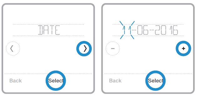
- Touch Menu on the thermostat home screen.
- Touch the or arrows until you see DATE, then touch Select.
- Touch or to set the month, then touch Select to confirm.
- Continue to set day and year in the same way. Touch Select to save your changes.
Cleaning the thermostat screen
- With the clean screen option, you can lock the thermostat screen so you don’t accidentally change your settings when you clean. Follow the steps below to activate clean screen mode.
- Touch Menu on the thermostat home screen.
- Touch the or arrows until you see CLEAN SCREEN, then touch Select. The screen will deactivate for 30 seconds. A countdown timer will display the amount of time until screen reactivation.
Tip: To clean the thermostat screen, spray water or household cleaner onto a cloth, then use the cloth to clean the screen. Avoid abrasive cleaners and do NOT spray liquid directly on the thermostat.
Choosing Fahrenheit or Celsius
To select a temperature scale, follow the steps below.
- Touch Menu on the thermostat home screen.
- Touch the or arrows until you see TEMP
CALE, then touch Select. - Touch the or arrows to select FAHRENHEIT or CELSIUS then touch Done to save your changes.
- Touch Back to return to the thermostat home screen.

Alerts and reminders
Alerts and reminders are displayed via the alert symbol and alert number in the clock area on the home screen. You can read more information about active alerts, snooze or dismiss noncritical alerts in Menu/Alerts.
| Number | Alert/Reminder | Definition |
| 54 | Thermostat Humidity Sensor Error | The sensor of the thermostat has encountered an error. Please contact dealer to replace the thermostat. |
| 164 | Heat Pump Needs Service | Heat pump needs service. Contact dealer to diagnose and service heat pump. |
| 170 | Internal Memory Error | The memory of the thermostat has encountered an error. Please contact dealer for assistance. |
| 171 | Set the Date and Time | Set the date and time on your thermostat. The date and time are required for certain features to operate, like the program schedule. |
| 173 | Thermostat Temperature Sensor Error | The sensor of the thermostat has encountered an error. Please contact dealer to replace the thermostat. |
| 177 | Indoor Temperature Sensor Error | Wired indoor temperature sensor is not connected or there is a wiring short. Please contact dealer for assistance. |
| 178 | Outdoor Temperature Sensor Error | Wired outdoor temperature sensor is not connected or there is a wiring short. Please contact dealer for assistance. |
| 181 | Replace Air Filter (1) | Replace air filter (1). Reset the timer by touching the “dismiss” button on thermostat screen after it is replaced. |
| 182 | Replace Air Filter (2) | Replace air filter (2). Reset the timer by touching the “dismiss” button on thermostat screen after it is replaced. |
| 184 | Replace Humidifier Pad | Replace humidifier pad. Reset the timer by touching the “dismiss” button on the thermostat screen after it is replaced. |
| 185 | Replace Dehumidifier Filter | Replace the dehumidifier filter. Reset the timer by touching “dismiss” button on thermostat screen after it is replaced. |
| 187 | Clean or Replace Ventilator Filter | Clean or replace ventilator filter. Reset the timer by touching the “dismiss” button on thermostat screen after it is replaced. |
| 188 | Replace UV Bulb (1) | Replace UV Bulb (1). Reset the timer by touching the “dismiss” button on thermostat screen after it is replaced. |
| 189 | Replace UV Bulb (2) | Replace UV Bulb (2). Reset the timer by touching the “dismiss” button on thermostat screen after it is replaced. |
| Number | Alert/Reminder | Definition |
| 252 | AC Power Lost | If batteries used as backup power it would drain batteries quickly so Z-Wave communication needs to be turned off. The working power mode can only be changed when thermostat is NOT included in
a Z-Wave network. Either to exclude and include thermostat back in to Z-Wave network to change the power mode to LSS (power-save, sleep mode) or to resume AC power. You can check the actual power mode in the thermostat MENU/DEVICE INFO. |
| 405 | Battery Low | Battery low. Please turn the system mode to off and replace the batteries. |
| 407 | Battery Critical | Battery critical. Thermostat cannot control your system. Please replace the batteries immediately. |
| 546 | Z-Wave Not Configured | Z-Wave has a not been configured yet to receive commands from your Z-Wave network. Please follow steps on how to include thermostat in to Z-Wave network. |
| 547 | Z-Wave Radio Error | Z-Wave module is not operating. Thermostat cannot receive commands from your Z-Wave network. Please contact dealer to replace the thermostat. |
Battery replacement
Batteries are optional (to provide backup power) if your thermostat was wired to run on 24 VAC power when installed. If your thermostat was wired to run on 24 VAC power, then batteries are NOT required. Install fresh batteries immediately when the low battery alert appears. The alert appears about two months before the batteries are depleted. Even if the low battery alert does not appear, you should replace batteries once a year, or before leaving home for more than a month. If batteries are inserted within two minutes, the time and day will not have to be reset. All other settings are permanently stored in memory, and do not require battery power.
NOTES:
- When replacing batteries, alkaline batteries are
- When the battery power is low, the thermostat’s backlight is disabled to save battery

- When battery power is critically low, only the alert icon and the battery icon are displayed, and the thermostat cannot control your HVAC system. Batteries must be replaced immediately. When the low battery alert appears, press gently to loosen the thermostat and then carefully pull it from the wall mount.
Troubleshooting
If you have difficulty with your thermostat, please try the following suggestions. Most problems can be corrected quickly and easily.

1-year limited warranty
Resideo warrants this product, excluding battery, to be free from defects in workmanship or materials, under normal use and service, for a period of one (1) year from the date of first purchase by the original purchaser. If at any time during the warranty period the product is determined to be defective due to workmanship or materials, Resideo shall repair or replace it (at Resideo’s option).
If the product is defective,
- return it, with a bill of sale or other dated proof of purchase, to the place from which you purchased it; or
- call Resideo Customer Care at 1-800-633-3991. Customer Care will make the determination whether the product should be returned to the following address: Resideo Return Goods, Dock 4 MN10-3860, 1885 Douglas N., Golden Valley, MN 55422, or whether a replacement product can be sent to you.
This warranty does not cover removal or reinstallation costs. This warranty shall not apply if it is shown by Resideo that the defect was caused by damage which occurred while the product was in the possession of a consumer. Resideo’s sole responsibility shall be to repair or replace the product within the terms stated above. RESIDEO SHALL NOT BE LIABLE FOR ANY LOSS OR DAMAGE OF ANY KIND, INCLUDING ANY INCIDENTAL OR CONSEQUENTIAL DAMAGES RESULTING, DIRECTLY OR INDIRECTLY, FROM ANY BREACH OF ANY WARRANTY, EXPRESS OR IMPLIED, OR ANY OTHER FAILURE OF THIS PRODUCT. Some states do not allow the exclusion or limitation of incidental or consequential damages, so this limitation may not apply to you. THIS WARRANTY IS THE ONLY EXPRESS WARRANTY RESIDEO MAKES ON THIS PRODUCT. THE DURATION OF ANY IMPLIED WARRANTIES, INCLUDING THE WARRANTIES OF MERCHANTABILITY AND FITNESS FOR A PARTICULAR PURPOSE, IS HEREBY LIMITED TO THE ONE YEAR DURATION OF THIS
WARRANTY. Some states do not allow limitations on how long an implied warranty lasts, so the above limitation may not apply to you. This warranty gives you specific legal rights, and you may have other rights which vary from state to state. If you have any questions concerning this warranty, please write Resideo Customer Care, 1985 Douglas Dr, Golden Valley, MN 55422 or call 1-800-633-3991
CAUTION: ELECTRICAL HAZARD
Can cause electrical shock or equipment damage. Disconnect power before beginning installation.
CAUTION: MERCURY NOTICE
If this product is replacing a control that contains mercury in a sealed tube, do not place the old control in the trash. Contact your local waste management authority for instructions regarding recycling and proper disposal
Customer assistance
For assistance with this product,
please visit honeywellhome.com/support
Or call Customer Care toll-free at 1-800-468-1502

Resideo Inc., 1985 Douglas Drive North

Golden Valley, MN 55422 www.resideo.com
This product is manufactured by Resideo Technologies, Inc., Golden Valley, MN, 1-800-633-3991.
The Honeywell Home trademark is used under license from Honeywell International Inc. All rights reserved. ©2019 Resideo Technologies, Inc. 33-00450ES—05 M.S. Rev. 09-19
REFERENCE:
Download Manual:
Honeywell Home RCHT8600 Z-wave Programmable Thermostat Quick Installation Guide

![]()
Honeywell Home RCHT8600 Z-wave Programmable Thermostat Quick Installation Guide