GoControl GC-TBZ48 Z-Wave Smart Thermostat

INSTALLATION INSTRUCTIONS
The Z-Wave Thermostat (GC-TBZ48) is a programmable, Z-Wave communication thermostat. It can be powered using 24VAC (if both “R”&”C” wires are available at the thermostat), or using four (4) AA batteries. Using Z-Wave technology, end users have the ability to use the 2GIG Go! Control panel to control the thermostat, configure programming settings, as well as to display current conditions in the home or office.
Figure 1. Z-Wave Thermostat Front View

Box Contents
- 1─Z-Wave Thermostat
- 1─Sheet Adhesive Wiring Labels
- 2─Plastic Wall Anchors
- 4─AA Batteries
Features Include:
- A fi xed format display with white backlight
- Heating and cooling setup display options
- System mode (OFF, Heat, Cool, Auto, E-Heat)
- Fan mode control and display (Auto, ON)
- Changeover type for Heat Pump (HP) systems
- On-screen setup of HVAC type, Fan type
- F/C mode, and sensor calibration
Standard Systems
- 1 Stage Heating and Cooling
- 2 Stage Heating and Cooling
Heat Pump Systems
- 1 Stage Heating and Cooling
- 2 Stage Heating and Cooling
- 2nd or 3rd Stage Aux Heating (Electric Heat Strips
Installation Outline
- Step 1 Remove Existing Thermostat
- Step 2 Install GC-TBZ48 Thermostat
- Step 3 Setup Thermostat to match the System Type
- Step 4 Install into Z-Wave Network
Wiring
Typical Wiring for Standard Gas/Electric HVAC System
Typical Wiring for Heat Pump HVAC System

- Thermostat Power
The thermostat can be powered by either 24VAC from the HVAC system or from four (4) type AA internal batteries. DO NOT use this thermostat for line voltage controls (120/240VAC). - The C Wire
If the 24VAC common wire (usually blue) is present and is connected to 24VAC common at the HVAC system end, the thermostat can be powered from the HVAC system and batteries are not required. If there is no common wire, batteries are required. - 24VAC Power
Powering the thermostat with 24VAC power requires both the 24VAC “C” common wire (typically a blue wire) and the 24VAC ”R” return wire (typically a red wire). - Battery Power
Powering the thermostat from batteries does not require a “C” wire connection. DO NOT install batteries if the thermostat is powered by 24VAC. They are not required for backup. If the thermostat is powered by batteries, the thermostat will operate for approximately (2) two years on four (4) AA Alkaline batteries depending on the frequency of user operations and backlight operation. Always use Alkaline batteries and replace in complete sets of four (4) at a me.
Z-Wave Operation when Battery Powered
IMPORTANT: If the thermostat is installed on a Z-Wave network, while it is battery-powered, it will NOT work as a Z-Wave repeater.
CAUTION: Do not install batteries and temporarily power the thermostat from 24VAC to include onto a Z-Wave network. Shortened battery life may occur when 24VAC power is removed
Remove Existing Thermostat
- Turn off the power to the thermostat. This is usually done at the heating/cooling system or circuit breaker panel.
- Remove the cover of old thermostat to expose the wiring terminals.
- Take a picture of the wiring terminals and the wires before disconnecting them!
- Mark the existing thermostat wires with the wiring labels included according to the terminal markings. Some installations may have additional wires not shown in this example illustration. Y1, Y2, W1, W2, O,B.
- Use the thermostat terminal “names/marking” (not the wiring color) to mark the wires.
- Remove the old thermostat base.
CAUTION: When removing the thermostat, don’t let the wires slip into the wall, and don’t let the wires touch each other. - If the old thermostat was a mercury-style thermostat, dispose of it properly as described below.
Figure 2. Label Wire Terminals
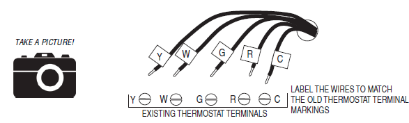
NOTE: Taking a picture is critical if problems are encountered. This will allow reinstallation of the old thermostat and will help with troubleshooting later if needed
Wiring Colors
While the thermostat terminal markings are intended to match the wire color, (R=RED, G=GREEN, W=WHITE, Y=YELLOW) be sure to follow the terminal marking when marking the wires, even if the wire color doesn’t match.
WARNING: If the existing thermostat is a mercury-containing device, it must be disposed of in compliance with federal, state, and local regulations. Many states and /or local agencies have collection/exchange programs or hazardous waste collected programs for mercury-containing devices. For more information, see the U.S. Environmental Protection Agency website at:http://www.epa.gov/osw/hazard/wastetypes/universal/mce.htm For Canada: Environment Canada and Disposing of Mercury Products at: https://www.ec.gc.ca/mercuremercury/default.asp?lang=En&n=F111AAC6-1.
Install the Back Panel
Remove the back panel of the thermostat by pushing down the thumb tab on the bottom of the body.
Figure 3. Removing the back panel of thermostat.
Mount the thermostat back panel on the wall (See Figure 4).
- Use the two (2) wall anchors and two (2) Phillips screws (provided) to mount the back panel.
- Level as needed.
Figure 4. Mounting the Back Panel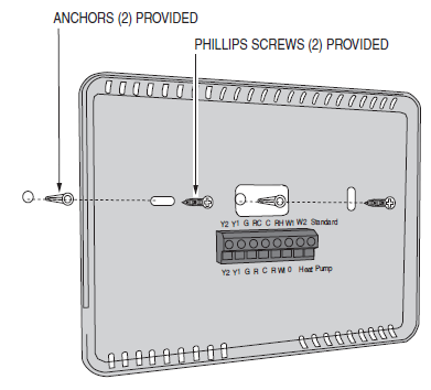
Standard HVAC System Connections
NOTE: For typical connections to a Standard HVAC system, refer to the diagram on Page 2. The terminals on the back panel have two sets of labels. The upper label shows the STANDARD HVAC terminal connections. The lower label shows HEAT PUMP HVAC terminal connections.
Figure 5. Standard HVAC System Terminal Block Labeling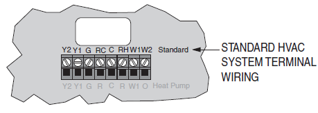
Figure 6. Standard HVAC Systems Terminal Block Connections 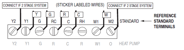
Single and Dual Transformer Systems (Split Systems) HVAC systems may have one or two transformers. The “R” wire connects differently depending on the system.
Single Transformer System
Most HVAC systems have a single 24VAC transformer. For these systems, there is only one “R” wire and it can be connected to either the thermostat’s RC or RH terminal as these are internally jumpered together.
If installing a Standard HVAC system, connect the wires from the HVAC system to the corresponding terminals on the thermostat back terminal block. Use the table below as a guideline for connecting the wires.
Dual Transformer Systems
For HVAC systems that have separate heating and cooling systems, each with their own 24VAC transformers, there will be an “R” wire from the heating system and an “R” wire from the cooling system. For dual transformer systems, connect the “C” wire from the cooling system to the thermostat’s “C” terminal. DO NOT CONNECT THE “C” WIRE FROM THE HEATING SYSTEM.
Figure 7. Dual Transformer HVAC System Thermostat Terminal Connections
IMPORTANT! FOR SEPARATE RC/RH SYSTEMS, THE INTERNAL RC=RH JUMPER MUST BE CUT ON THE BACK OF THE THERMOSTAT’S PRINTED CIRCUIT BOARD— (See Figure 8).
Figure 8. Internal RC=RH Jumper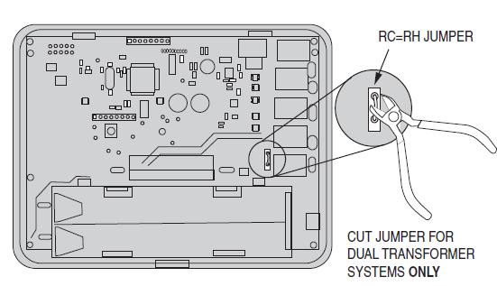
Heat Pump HVAC System Connections
NOTE: For typical connections to a Heat Pump HVAC system, refer to the diagram on Page 3. The terminals on the back panel have two sets of labels. The lower label shows HEAT PUMP HVAC terminal connections. The upper label shows the STANDARD HVAC terminal connections
Figure 9. Heat Pump HVAC System Terminal Block Labeling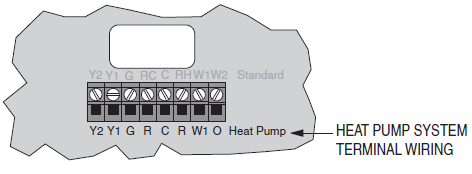
Figure 10. Heat Pump HVAC System Thermostat Terminal Block Connections
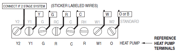
Connect the wires from the HVAC system to the corresponding terminals on the thermostat back terminal block. Use the table below as a guideline for connecting the wires.
Mount the Thermostat
Install the thermostat body/front panel onto the wall-mounted base by firmly pressing it in place until it snaps all around the edges. The GC-TBZ48 is now ready to program.
Figure 11. Attaching Front Panel to Back Panel
Battery Installation
If installing batteries, open the thermostat battery front panel, and pry it off with a finger nail at the indents on the bottom of the case (See Figure 12). Install the four (4) type AA batteries and assemble them as shown in Fig.13.
Figure 12. Opening Battery Case/Cover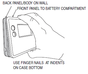
Figure 13. Battery Installation
Thermostat Setup Menus
- The thermostat must be set for the correct HVAC system type for proper operation.
- Preset HVAC System settings
The thermostat is preset for the following typical HVAC system configuration:
- HVAC system type: Standard gas/electric
- HVAC fan type: Gas heat
- HVAC heating stages: one
- HVAC cooling stages: one
If the thermostat is installed on this type HVAC system, the System Setup does not need to be changed. If installed on a Heat Pump HVAC system or any HVAC configuration other than the preset settings change the settings in the SYSTEM setup menu to match the HVAC system.
NOTE: To conserve battery life, the thermostat backlight turns off after a short me of no activity. The first press of any button turns on the backlight (but does not initiate any action). Press the button again to initiate the action desired. If the backlight is already on, button presses work with the first press.
Wait Mode
The thermostat has a Minimum of Time (MOT) delay after any heating or cooling cycle ends. This delay prevents rapid heating/cooling cycles and also provides “short cycle protection on” for the system compressor. This delay may be not cable when you change a setpoint and it does not respond immediately due to the MOT delay mer preventing the system from restarting. The MOT delays can be adjusted in the Advanced settings menu of the thermostat but there is a minimum of five minutes delay to assure compressor protection.
Minimum Run Time (MRT)
The thermostat has a Minimum Run Time delay after the start of any heating or cooling call. This minimum run time assures even heating and cooling cycles. The MRT will keep the system on, even if it reaches the setpoint room temperature, or you change the setpoint to a temperature that would satisfy the call until the MRT expires. Changing the Mode to OFF will cancel the MRT and the system will turn off immediately. The MRT can be adjusted in the Advanced Settings menu of the thermostat.
NOTE: The MRT delays are shown by flashing heat or cool icons on the display
Entering Menu Mode
- To change the System setup, go to the thermostats Menu Mode and select SYSTEM. From there
- Select the correct HVAC settings to match the installation type.
- Press and hold the FAN button to enter the Menu Mode. SETUP is the first menu item displayed.
- Press the
 button to advance to the SYSTEM screen.
Figure 14. Menu Mode Setup
Menu Mode Navigation
When the Thermostat Menu Mode screen is displayed, press the buttons to scroll through the following menu items.
Figure 15. Menu Navigation

The following menu items are displayed in order.
- SETUP (user preference settings)
- SYSTEM (HVAC system setup)
- Z-WAVE (install/uninstall from Z-Wave network)
- CLOCK (set me and day)
- INFO (firmware versions and Z-Wave network information
The SYSTEM menu is used to setup the thermostat for the correct HVAC system type. The following setup options will be displayed in the text line:
- HVAC System Type: Standard Gas/Electric or Heat Pump
- Fan Type: Gas Heating or Electric Heating
- Changeover Valve Type (for Heat Pump Systems): Changeover with Cooling or with Heating.
To select options:
- Use the
 buttons to scroll to the desired settings
 - Press SELECT to change a setting. The current setting for that selection will be flashing.
- Change the option with the buttons.
- When the desired option has been selected, Press SELECT again to save it.
- Then press DONE to exit.
System Type
- For Standard Gas/Electric systems, select STANDARD This is the default settings
- For Heat Pump systems, press the buttons to change to HEAT PUMP
- Press SELECT to set.
- Press DONE to exit.
- Fan Type (For Standard HVAC systems only)
- Fan type depends on the heating system type.
- For Gas heat: select GAS. This is the default settings
- For Electric heat: press the buttons to change to ELECTRIC.
- Press SELECT to set.
- Press DONE to exit.
Changeover Type (For Heat Pump HVAC Systems Only)
The changeover (or reversing) valve is used to change from heating to cooling operation. The HVAC system is either a Changeover with Cooling type (O) or a Changeover with Heating type (B). Most are changeover with cooling, which is the default setting.
- For Changeover with Cooling systems, select WITH COOL. This is the default setting.
- For Changeover with Heating systems, use the buttons to change to WITH HEAT.
- Press Select to set.
- Press Done to exit.
Not sure what type of Changeover system? Check the existing thermostat connecttions to help determine this. If the original system had an orange wire connected to an “O” terminal, then this is a “changeover with cool” system. If there was a brown wire connected to a “B” terminal, then this is a “change over with heat” system. Set the Changeover setting accordingly.
NOTE: If heating comes on when cooling is expected or vice versa, switch the “Changeover Type” to the opposite setting.
Z-Wave Installation
Z-Wave controllers from various manufacturers may support the Z-Wave Thermostat General V2 Device class used by the Go Control Z-WAVE Thermostat. The following procedure will allow the thermostat to be added to a Z-Wave network.
NOTE: Before adding the thermostat to a Z-Wave Network, check that it does not already belong to one by viewing the Node ID (ZNID) located in the Thermostat Info screen. An uninstalled thermostat should show zeros for the Node ID (000). Consult your controller’s user manual for details on removing a device from a Z-Wave network.
Figure 16. Z-Wave Menu Setup
General Programming Procedure (for controllers supporting the thermostat device class):
- Set your primary controller to Include, add or Install mode, to add the thermostat as a node on your network (see your controller’s user manual for detailed instructions).
- Press any button to take the thermostat out of sleep mode.
- Press and hold the FAN button for 5 seconds. SETUP will be displayed in the status display line.
- Scroll to “Z-Wave” using buttons. Press SELECT.
- When prompted by your Z-Wave controller, Press the YES button in the Z-Wave Install screen.
- Press SELECT (mode button) to add the thermostat to the network.
- Display line should fl ash WAIT then SUCCESS if Z-Wave connection is made.
- If Z-Wave does not connect to the controller, WAIT, then FAIL will flash in the status display line.
- If the thermostat fails to connect, repeat Steps three (3) thru (7) to re-try connecting.
Your controller will indicate the thermostat was successfully added to its network (see your controller’s user manual for details). Also, you can check if the thermostat was successfully added to the network by checking the ZHID (Home ID) and ZNID (Node ID) located in the Thermostat Info screen. For other specific tasks such as adding the thermostat to Scenes or Groups, or deleting the thermostat from an existing network, refer to the Z-Wave controller instructions.
Inclusion and Exclusion
Inclusion or exclusion is started by putting the controller into add node or remove node state and performing the General Programming Procedure outlined above. As part of the process, the thermostat sends a node informaon frame at normal power. Low power inclusion or low power exclusion is not possible.
CAUTION: Do not install batteries and temporarily power the thermostat from 24VAC to include onto a Z-Wave network. Shortened battery life may occur when 24VAC power is removed
Clock Menu
Use the clock menu to set the thermostat’s internal clock.
Figure 17. Clock Setup
Setting the Clock
- Press any button to take thermostat out of sleep mode.
- Press FAN button for 5 seconds until, SETUP appears in status display line.
- Use buttons to select CLOCK in the status display line.
- Press SELECT, DAY will be displayed
- Press buttons, TIME will be displayed.
- Use the buttons to select the current me.
- Press SELECT, FAN (Done), FAN (Done).
INFO Menu
The INFO menu displays information about the thermostat. Use the buttons to scroll through the various items.
- MODEL GC-TBZ48
- VERSION Thermostat firmware version.
- ZWAVE Z-Wave fi rmware version.
- NODE ID Z-Wave Node ID.
- HOME ID Z-Wave Home ID.
- SYSTEM TYPE displays the current System Type setting.
- If System Type = Standard, FAN TYPE displays the current Fan Type setting.
- If System Type = Heat Pump, CHANGEOVER TYPE displays the current Change Over setting.
Advanced System settings Menu
- The Advanced System Settings Menu provides additional system setup options.
- These settings can affect system operation and should only be changed by qualified HVAC installers.
- To access the Advanced System settings menu, first press and hold the FAN button to get into the
- Setup menu. While in the Setup Menu, press and hold both the FAN and buttons for 5 seconds.
- Use the buttons to scroll through the menu options to the desired setting.
- Press the SELECT (Mode) button to change a setting. Once it begins to flash, use the buttons to select the desired setting.
- Press the SELECT button to accept the new setting (flashing will stop).
Thermostat Operation
Main Thermostat Screen

Backlight and Button Operation
The thermostat backlight is normally set to go out after 20 seconds of no button presses to conserve battery power. If the backlight is off , the first button press of any button will only turn on the backlight. Once the backlight is on, the button functions normally.
Display

 displayed > System is ON and heating
- Blinking> System is ON and heating. Minimum Run Time (MRT) delay is active
 displayed > System is ON and cooling
- Blinking> System is ON and cooling. Minimum Run Time (MRT) delay is active
Staging Indicators
- “1” = Stage 1 heating or cooling is ON
- “2” = Stage 2 heating or cooling is ON
- “3” = Stage 3 heating (Aux Heat) is ON
For Heat Pump systems only:
- “Heat-E” = Emergency heat mode active
Settings the System Mode
System Modes
- Off: The system is off. No heating or cooling will come on. If the system was on, it will turn off immediately.
- Heat: Only heating will occur.
- Cool: Only cooling will occur.
- Auto: Heating or cooling will come on according to the heating and cooling setpoints.
The system will automatically switch between heating and cooling modes as needed to maintain the setpoints.
Special Heat Pump Mode: Emergency Heat
An additional system mode, “Heat-E” for Emergency Heat will be displayed if the HVAC System Type is set to Heat Pump. If there is a compressor failure with the Heat Pump system, setting the mode to Emergency Heat will allow the supplemental Aux Heat to come on first whenever there is a call for heating. It also disables the compressor output to prevent further damage to the HVAC system.
CAUTION! Emergency Heat should only be used for emergencies until the HVAC system can be repaired. Running the system in Emergency Heat mode is commonly the most expensive mode since only the electric heat strips are being used instead of the more efficient heat pump compressor\
Setting the Heating or Cooling Temperature Setpoint
To change the setpoint, press the buttons. The screen will switch to the setpoint change screen and show the current setpoint of the current heating or cooling mode. Adjust the setpoint temperature up or down with the buttons.
NOTE: When in the Setpoint Change screen, pressing the MODE button will switch the setpoint being displayed between the Heat and Cool setpoints.
Figure 21. Accessing Setpoints
Figure 22. Setpoint Change Screen 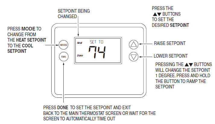
Automatic Setpoint Push
The cooling setpoint cannot be set below the heating setpoint. The thermostat will “push” the heating setpoint lower if the cooling setpoint is set below the current heating setpoint. A 3-degree separation is maintained between the heating and cooling setpoints. The same is true for raising the heating setpoint above the cooling setpoint. The thermostat will “push” the cooling setpoint up to maintain the 3-degree separation.
Settings the Fan Mode
Fan Modes
- Use the FAN button to select the HVAC system’s fan mode.
- Auto: Fan automatically operated by the HVAC system (normal setting).
- On: Manual Fan mode. Fan stays on until mode is changed back to Auto, independent of the heating or cooling system operation.
User Customization
Figure 24. Selecting Menu Mode
Figure 25. Menu Navigation 
User preference settings
- FAHRENHEIT OR CELSIUS. Select the temperature display mode.
- BACKLIGHT TIMEOUT. Sets me from the last button press that the backlight will turn OFF.
- Range: 10-30 seconds. Note: Long backlight timeouts will reduce battery life.
Note: If the thermostat is powered from 24VAC, the backlight timeout can be set to “0” which will keep the backlight on continuously.
- SENSOR CALIBRATION Change the temperature calibration by +/- 7 degrees. Press the UP or
- DOWN arrow buttons to change to the desired display temperature.
- STATUS LINE. Sets Status Line to Setpoints or Clock mode.
Clock Menu
Use the clock menu to set the thermostat’s internal clock.
Setting the Clock
- Press any button to take the thermostat out of sleep mode.
- Press the FAN button for 5 seconds until SETUP appears in the status display line.
- Use the button to select CLOCK in the status display line.
- Press SELECT, DAY will be displayed
- Press buttons, TIME will be displayed.
- Use the buttons to select the current me.
- Press SELECT, DONE, DONE.
INFO Menu
The INFO menu displays information about the thermostat. Use the buttons to scroll through the various items.
- MODEL NTBZ48
- VERSION Thermostat fi rmware version.
- ZWAVE Z-Wave fi rmware version.
- NODE ID Z-Wave Node ID.
- HOME ID Z-Wave Home ID.
- SYSTEM TYPE displays current System Type setting.
- If System Type = Standard, FAN TYPE displays current Fan Type setting.
- If System Type = Heat Pump, CHANGEOVER TYPE displays current Change Over setting.
- Battery xx% = Battery Level (If battery powered)
Specifications
- Power C-Wire Input: 20-30VAC
- Battery Power: 4 AA Batteries
- Operating Temperature 32° to 120°F (0° to 49°C)
- Storage Temperature -40° to 140°F (-40° to 60°C)
- Messaging Capability 7 character alpha numeric display, with message scroll
- Set-point Accuracy 1° F (0.5°C), Calibrates to +/- 7°F
- Ambient Temperature Display
- Accuracy 1° F (0.5°C)
- Remote Control Via Z-Wave
- Standard Gas/Electric HVAC
- Systems 2-stage heating, 2-stage cooling
- Heat Pump HVAC System 3-stage heating, 2-stage cooling
- Thermostat Connections Uses standard thermostat connections (C,RC,RH,W1,W2/O,Y1,Y2,G) – 18 AWG
- Regulator United States: FCC Compliant to CFR47, Part 15B Canada: Industry Canada RSS 210, Issue 8
- Dimensions 5.75” (146mm) W, 4.5”(114.3mm) H, 1.00 (25.4mm) D
- Screen Size 2.7” X 1.4” LCD w/white backlight (68.6mm X 35.6mm)
- Buttons 4 mechanical buttons (Mode, Fan, Up Arrow, Down Arrow)
- Certification FCC Part 15, Industry Canada
Regulatory Information
FCC
This device complies with Part 15 of the FCC Rules. Operation is subject to the following two conditions:
- This device may not cause harmful interference, and
- This device must accept any interference received, including interference that may cause undesired operation.
This equipment has been tested and found to comply with the limits for Class B Digital Device, pursuant to Part 15 of the FCC Rules. These limits are designed to provide reasonable protection against harmful interference in a residential installation. This equipment generates and can radiate radio frequency energy and, if not installed and used in accordance with the instructions, may cause harmful interference to radio communications. However, there is no guarantee that interference will not occur in a particular installation. If this equipment does cause harmful interference to radio or television reception, which can be determined by turning the equipment off and on, the user is encouraged to try to correct the interference by one or more of the following measures.
- Reorient or relocate the receiving antenna
- Increase the separation between the equipment and receiver
- Connect the equipment into an outlet on a circuit different from that to which the receiver is connected
- Consult the dealer or an experienced radio/TV technician for help
Any changes or modifications not expressly approved by the party responsible for compliance could void the user’s authority to operate the equipment.
Limited Warranty
This Nortek Security & Control LLC product is warranted against defects in material and workmanship for one (1) year. This warranty extends only to wholesale customers who buy direct from Nortek Security & Control or through Nortek Security & Control normal distribution channels. Nortek Security & Control does not warrant this product to consumers. Consumers should inquire from their selling dealer as to the nature of the dealer’s warranty, if any. There are no obligations or liabilities on the part of Nortek Security & Control for consequence al damages arising out of or in connectton with use or performance of this product or other indirect damages with respect to loss of property, revenue, or profit, or cost of removal, installation, or reinstallation. All implied warranties for functionality, are valid only until the warranty expires. This Nortek Security & Control Warranty is in lieu of all other warranties express or implied
Go Control
- 1950 Camino Vida Roble, Suite 150
- Carlsbad, CA 92008 USA
- For technical support in the USA and Canada:
- Dial: 855-2GIG-TECH (855-244-4832)
- Email: [email protected]
- Visit the website for technical support hours of operation
- For technical support outside of the USA and Canada:
- Contact your regional distributor
- Visit www.2GIG.com or dealer.2gig.com technical support hours of operation
REFERENCE
DOWNLOAD MANUALS:
GoControl GC-TBZ48 Z-Wave Smart Thermostat Installation Instruction
OTHER MANUALS:
GoControl GC-TBZ48 Z-Wave Smart Thermostat Product Data Sheet

GoControl GC-TBZ48 Z-Wave Smart Thermostat Installation Instruction