Glow-Worm Climapro1 Wireless Room Thermostat

INTRODUCTION
Product documentation
The instructions are an integral part of the Climapro1 RF and must be handed to the user on completion of the installation in order to comply with the current regulation.
- Carefully read the manual, to enable safe installation, use and servicing. No liability can be accepted in the event of damage for not complying with the guidance in this instruction manual.
CE Mark
- European Directive Num. 2004-108 of the European Parliament and the Council regarding electromagnetic compatibility
- European Directive Num. 2006-95 of the European Parliament and the Council regarding low voltage
- Directive regarding telecommunications equipment ( Directive R & TTE 99/5/ EEC of the Council of the European Community)
The CE mark indicates that the units described in this manual are in compliance with the following directives:
INSTALLER
Climapro1 installation
List of contents
Climapro1 programmable room thermostat Wall support for the Climapro1 (*)
Radio receiver
AA LR6 “alkaline batteries” (*) (*) delivered with the wireless version
Fixing
- Wired room thermostat
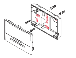
- Wireless room thermostat
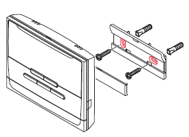
- Radio receiver
radio receiver on control box unit
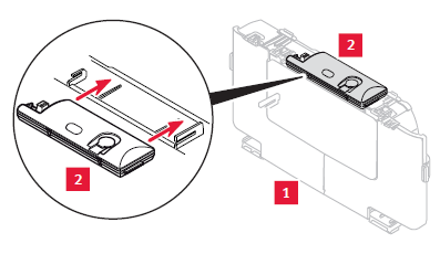
Key
- Control box unit
- Radio receiver
Slide the radio receiver into the notches.
IMPORTANT: It is easier to pass the EBUS cable if the pre-cut part is removed.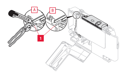
Key
- Pre-cut part of the electrical box
radio receiver in the control box unit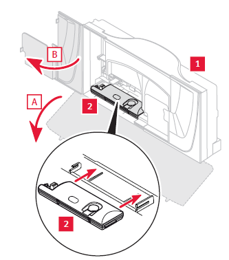
Key
- Control box unit
- Radio receiver
IMPORTANT: The receiver should be installed outside the appliance if the appliance control box does not have a location for the radio receiver
radio receiver outside appliance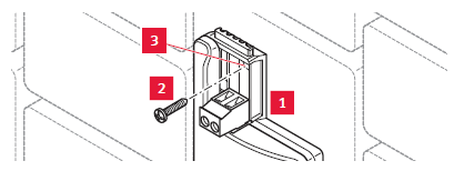
Key
- Radio receiver
- Fixing screw
- Drilling
Electrical connections
DANGER: Incorrect installation can cause electric shock or damage to the equipment. The electrical connection must be made only by a qualified engineer.
ATTENTION: Do not connect the room thermostat to a 230V terminal.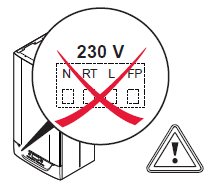
IMPORTANT: Do not remove the link (RT 24V) from the room thermostat connection on the boiler main PCB.
- Use a connecting cable that complies with the technical specifications (refer to the technical data chapter).
IMPORTANT: The location of the EBUS terminal block varies according to the heating system. It is always identified by having «BUS» written on it.
Wired room thermostat
connected to a boiler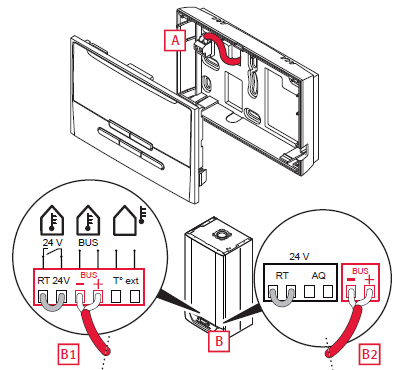
Key
- A connection on the room thermostat:
- B connection to the EBUS 24V terminal on the boiler (examples B1 & B2)
connected to Smart Wiring Centre 2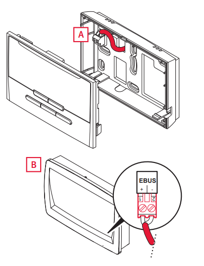
Key
- A connection on the room thermostat:
- B connection to the EBUS 24V terminal on the control box

Key
- A connection on the radio receiver:
- B connection to the EBUS 24V terminal on the boiler (examples B1 & B2)
connected to Systempro
The radio receiver function is integrated into the Systempro. There is no electrical connection to be made in an installation including a Systempro.
Commissioning
- Switch on the appliances that make up the installation (see the installation manuals).
- If using the Climapro1 RF, remove the insulating tab in the room thermostat battery compartment.
- Follow the instructions given by the installation assistant.
- Make the adjustments and select the necessary options depending on the installation.
- Finalise the installation in the installer menu.
- Check that these main settings are compatible with the installation.
- Check the installation by issuing a heating demand.
The installation menu is still accessible after commissioning.
- Press the button
 for 7 seconds .
 - Enter the installer access code (96).
Returning to the user menu
- Press the button for 3 seconds to return to the main user screen.
The installer menu customizes itself depending on the appliance it is connected to and the connection method.
New functions
Automatic heating curve (if an outdoor sensor is connected)
The automatic heating curve function continually seeks the most suitable value to ensure your comfort and the efficiency of your heating system. The optimum value is obtained approximately 24 hours after the system is started. It is recommended that you activate this function. If the function is deactivated, the heating curve can be set manually by the installer.
- Thermostat function (if an outside sensor is connected)
- The heating system alters the water temperature in the heating circuit depending on: the ambient temperature, the outside temperature.
- If this function is deactivated, the heating system no longer takes into account the ambient temperature. The heating system uses just the outside temperature.
Anticipation
The heating system anticipates the fi rst programmed setting change in the morning. This function allows it to reach the programmed temperature rapidly (the function is available and independent for each zone).
Performance index
The performance indicator is calculated from the effi ciency of all appliances over the last 24 hours. The cursor moves along a scale graduated.
Service reminder
- This function reminds the end user to service the appliance. The user must plan the maintenance of their system.
- The date must be entered into the installer menu during installation and after each maintenance.
- The icon
 is displayed on the room thermostat screen 30 days before the date entered into the installer menu.
Tree diagram
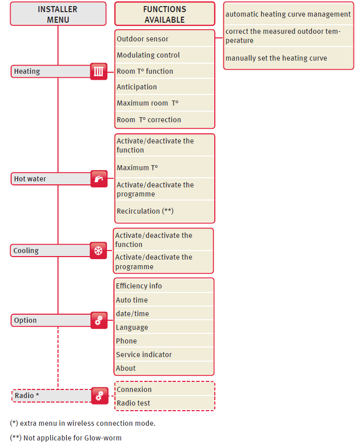
| Main settings | |
| Heating | |
| Maximum room T° | 30°C |
| Room T° correction | 0°C |
| Modulating control | on |
| Room T° function | on |
| Anticipation | off |
| Domestic hot water | |
| On/Off | on |
| Program | off |
| Maximum T° | 60°C |
| Recirculation (**) | off |
| Cooling | |
| On/Off | off |
| Program | off |
| if an outdoor sensor is connected | |
| Automatic heating curve | on |
| Correct the outdoor temperature | 0°C |
| Settings | |
| Efficiency info | off |
| Auto time | on |
| Service indicator | off |
Climapro1 can be the master or secondary room thermostat:
Master
The “master” room thermostat of the installation has all functions available. The installation comprises only one main room thermostat. It is in general in the principal part of the dwelling (zone 1).
Secondary
The “secondary” room thermostat located in another part has a limited number of functions.
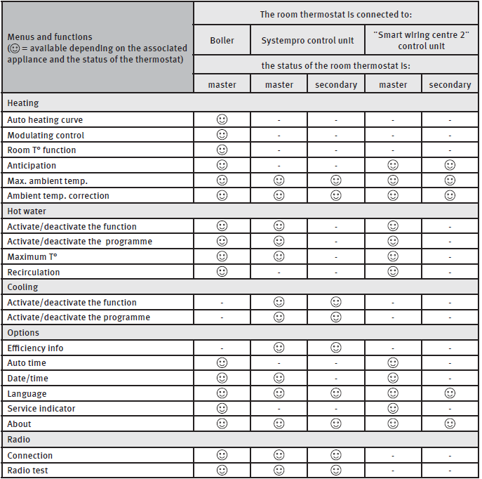
Compatibility of the room thermostat
| Room thermostat version |
Appliance |
Systempro |
Smart wiring center 2 |
| wired |  |
– | |
| wireless | |
|
– |
MAINTENANCE
Troubleshooting
Fault diagnosis
The following checks should be performed before proceeding onto specifi c diagnostics
- Check the error messages in the room temperature thermostat’s display zone
Wired room thermostat
IMPORTANT:
If the room thermostat becomes disconnected from the boiler, the heating system uses its own operational settings. Check that these settings are compatible with the installation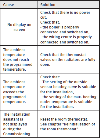
IMPORTANT:
The settings are recorded in the room thermostat and the wireless receiver.
If the wireless receiver becomes disconnected from the boiler, the heating system uses its own operational settings. Check that these settings are compatible with the installation.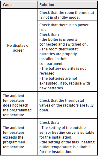
Radio receiver
IMPORTANT: Faults described in this chapter should be rectifi ed by a qualifi ed engineer and if needed by the After Sales Service
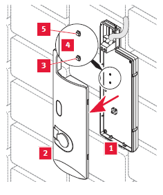
Key
- Radio receiver
- Cover for radio receiver
- Red LED
- Radio receiver circuit board
- Green LED
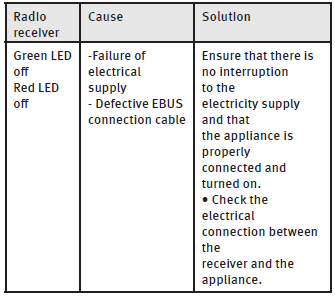
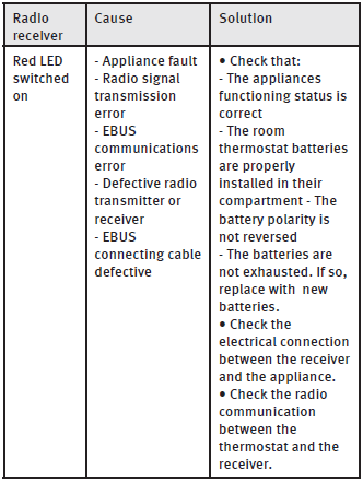
In the event of a problem:
- Remove the cover (2) from the radio receiver (1) to see the 2 LEDs.
- Check the state of the 2 LEDs (green (5) and red (3) located on the electronic board (4) in the radio receiver
Resetting the room thermostat
This function is used to return the room thermostat to factory settings. This restarts the installation assistant.
ATTENTION:
The resetting of factory settings is irreversible. All customised confi guration of the room thermostat will be lost.
- Simultaneously press the buttons

 for 10 seconds.
 - Confirm by pressing.OK
TECHNICAL DATA
Climapro
| Description | Unit | Climaplus RF |
| Room temperature authorized in the room where the control is installed | °C | 50 |
| The maximum authorised temperature of domestic water | °C | 65 |
| Power-supply voltage EBUS | V | 24 |
| Electrical connection cable section | mm² | 2 x 0.75 |
| Max. length of electric connection cables | m | 300 |
| Electrical protection | IP20 | |
| Pollution rating | 2 | |
| Dimensions: | ||
| Height | mm | 97 |
| Width | mm | 146.5 |
| Depth | mm | 35 |
Climapro1 RF
| Description | Unit | Climaplus |
| Room temperature authorized in the room where the control is installed | °C | 50 |
| Maximum authorized temperature of domestic water | °C | 65 |
| Power-supply voltage EBUS | V | 24 |
| Electrical connection cable section | mm² | 2 x 0.75 |
| Max. length of electric connection cables | m | 300 |
| Transmission/reception frequency | MHz | 868 |
| Electrical protection | IP20 | |
| Pollution rating | 2 | |
| Frequency of communication with outdoor sensor | min | 15 |
| Frequency of communication with the control box | min | 10 |
| Average unobstructed working range (*) | m | 100 |
| Average range within the home (*) | m | 25 |
| Thermostat dimensions: | ||
| Height | mm | 115 |
| Width | mm | 146.5 |
| Depth | mm | 41 |
| Wireless receiver dimensions: | ||
| Height | mm | 20 |
| Width | mm | 171 |
| Depth | mm | 58 |
| (*) Can vary according to installation conditions and electromagnetic environment | ||
SCAN ME
GLOW-WORM
Address: Nottingham Road, Belper, Derbyshire. DE56 1JT
www.glow-worm.co.uk
Because of our constant endeavour for improvement, details may vary slightly from those shown in these instructions.
Phone: 0020140263_00 – 11/11
Subject to engineering changes
Reference:
DOWNLOAD MANUALS:
Glow-Worm Climapro1 Wireless Room Thermostat Installation Guide

Glow-Worm Climapro1 Wireless Room Thermostat Installation Guide