
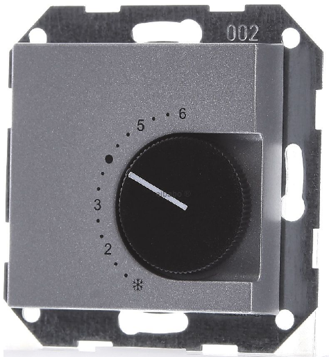
GIRA 039626 Room Temperature Controller Thermostat
Operating instructions
Room temperature controller 230/5 (2) A~ with 2-way switch
Installation of the room temperature controller
Area of application
The room temperature controller is used to control the temperature in closed rooms, such as apartments, schools, lecture halls, workshops etc.
The room temperature controller is used to control the temperature in closed rooms, such as apartments, schools, lecture halls, workshops etc.
Installation site
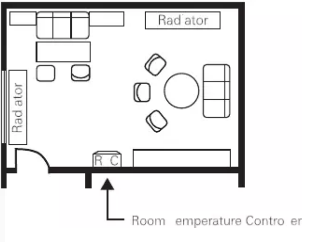
- Install the room temperature controller on an inte- rior wall and, if possible, directly across from the heat source.
- Comply with the recommended installation height of approx. 1.5 m above the floor.
- The permissible relative humidity may not exceed the max. of 95 %.
Avoid condensation.
- Avoid exterior walls and draughts from windows and doors Ensure that the normal convective air of the room can reach the room temperature controller unimpeded. For this reason, the controller is not to be mounted within shelf walls or behind curtains or similar coverings.
- Heat from other sources negatively influences con- troller precision.
- For this reason, avoid direct sunlight and objects which emit heat (televisions, heaters, lamps, chimneys, heating pipes etc.).
- Dimmers also generate heat!
- If the room temperature controller is used in conjunction with a dimmer, the distance between the two should be as great as possible. If aligned verti- cally, the room temperature controller should be installed below the dimmer.
Installation site
- The room temperature controller is mounted in a 58-mm flush-mounted box in accordance with DIN 49 073.
- To install the room temperature controller, proceed as follows:
- Remove housing cover:
- Pull off setting knob.
- Loosen cover screw.
- Pull off cover.
- Electrical connection in accordance with wiring schematic (see Page 10).
- Mount device into the flush-mounted box with screws. Attention: Always mount a support ring on the wallpaper. The support ring may not be wallpapered over when renovating.
- Set housing cover with cover frame in place. Engage housing cover at the top left in the housing basis and tighten screw. Attach the setting knob.
Electrical connection
Connect all cables in accordance with the wiring schematic (see Page 10). Ensure that the neutral conductor is connected to terminal N. If this is not done, great temperature fluctuations will result, as the room temperature controller cannot work properly. An earthed connection is not required, as the device is double insulated
Wiring schematic
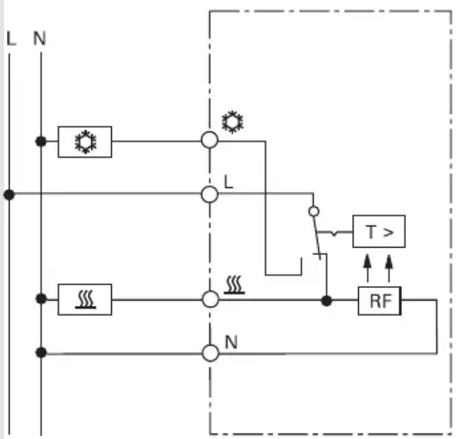
Key to wiring diagram
- L = external conductor
- N = neutral conductor
 = connection for clock signal for temperature reduction
 = heating load connection
 = cooling load connection
- RF = resistance for heat return
Setting the temperature limits
Two setting rings are found in the setting knob. You can set the temperature limits as desired with them. The temperature controller is set to the maximum setting range of 5 °C to 30 °C at the factory.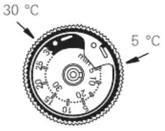
Setting procedure
- To set the temperature limits (in this example: min. 8 °C, max. 23 °C):
- Turn the setting knob to the center of the desired setting range.
- Example: The center between 8 °C and 23 °C is 15 °C.
- Pull off the setting knob
- To set the red setting ring to the upper-temperature limit (23 °C here)
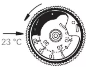
- Insert a pointy object (e.g. pen) into one of the holes of the red ring.
- Rotate the red ring anti-clockwise to 23 °C.
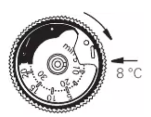
- The outer numbers of the scale apply here set the blue setting ring to the lower temperature limit (8 °C here)
- Insert a pointy object (e.g. pen) into the hole of the blue ring.
- Rotate the blue ring clockwise to 8 °C. The inner numbers of the scale apply here.
- Attach the setting knob. Here, the indicator must be located approximately at the center of the new setting range (see Item 1). Example: approx. 15 °C
Temperature adjustment
When commissioning the room temperature controller, note that the thermo-bimetal requires a certain amount of time to adjust to the room temperature. This is why the switching point will deviate from the room temperature immediately after mounting or after night-time heating reduction switches off. The switching point is not precise until after one to two hours of operation. For quick initial heating and to shorten the initial adjustment, we recommend set- ting the selected temperature higher than desired. Once the temperature has been reached, the temperature setting can be reset to the desired setpoint
Temperature setting scale
The scale for the temperature setting is found on the cover of the room temperature controller and is used for visual orientation when setting the temperature (from min. 5 °C to max. 30 °C).
- = approx. 5 °C
- = approx. 10 °C
- = approx. 15 °C
- = approx. 20 °C
- = approx. 25 °C
- = approx. 30 °C
Technical data
- Temperature range: 5 °C to 30 °C
- Rated voltage: 230 V AC
- Rated heating current: 10 (4)
- Max. contact rating: approx. 2200 W
- Rated cooling current: 5 (2) A
- Switching temperature differential: approx. 0.5 K
- Night-time heating reductions: approx. 4 K
- Conductor cross-section: 1 to 2.5 mm solid conductor
Warranty
The warranty is provided in accordance with statutory requirements via the specialist trade. Please submit or send faulty devices postage paid together with an error description to your responsible salesperson (specialist trade/installation company/electrical specialist trade). They will forward the devices to the Gira Service Center
Gira
- Giersiepen GmbH & Co. KG
- Elektro-Installations-
- Systeme
- Postfach 1220
- 42461 Radevormwald
- Deutschland
- Tel +49 (0) 21 95 / 602 – 0
- Fax +49 (0) 21 95 / 602 – 191
- www.gira.de
- [email protected]
Reference
Download MANUALS:
GIRA 039626 Room Temperature Controller Thermostat
GIRA 039626 Room Temperature Controller Thermostat Operating Instructions
Leave a Reply