
GE APPLIANCES Cync Smart Thermostat En Route
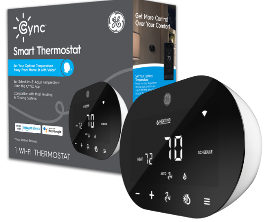
Compatibility Requirements
The Cync™ Smart Thermostat works with most central residential heating and cooling systems.
- Heating: Up to 2 stages
- Cooling: Up to 2 stages
- Heat Pumps: Up to 4 heating stages and up to 2 cooling stages
- Must be within range of 2.4GHz Wi-Fi to enable smart and out-of-home control.
- Minimum iOS and Android requirements: Android 8 or higher and iOS 14 or higher.
- Scan here to check your wiring compatibility before getting started.
Simple DIY Set Up
For detailed step-by-step instructions tailored to your home’s wiring configuration,use the Cync App installation guide.

- STEP 1
- Download the Cync App, powered by Savant, on your smartphone
- STEP 2
- Determine the thermostat wires present and complete installation
- STEP 3
- Add your Cync Thermostat to the Cync App
What’s Included

What You’ll Need

BEFORE YOU DO ANYTHING! Turn Off the Power!

Power off your HVAC System.
- Before doing anything, power off your system. Check for a master switch at your HVAC equipment. If there isn’t a master switch, please turn off the power at the circuit breaker box.
- After turning off the power, try adjusting the thermostat temperature to make sure the power is off.
- If you are uncomfortable installing the thermostat yourself, contact a qualified HVAC technician to complete installation.
Power Up!
Your Cync Thermostat provides more features than a traditional thermostat including out-of-home, voice,* and app control. The Cync Thermostat requires constant power so that it is always ready to respond to your voice* or Cync App.
There are two ways to provide the necessary power:

What’s the Difference Between a C Wire and PEK?

- C WIRE
- The C wire delivers power from the HVAC control board to your thermostat.
- POWER EXTENDER KIT (PEK)
- The PEK provides power to the thermostat when there are not enough wires available to connect to the C wire/ C terminal on the thermostat. A PEK is included in the box.
Let’s Determine How to Power Your Cync Smart Thermostat
Remove your existing thermostat panel and look at the wires attached. If you don’t see screws on the face plate, it should just pull off. Look for a wire connected to the C terminal. Oftentimes, the wire is blue.
Which Directions Do I Need to Follow for My Installation?

- YES, I DO HAVE A C WIRE
- Proceed to the next page.
- NO, I DON’T HAVE A C WIRE
- We’ve got you covered. It will take a few extra steps, including installing a PEK in your HVAC unit. Go to page 27 to get started.
For New Installations, Choose a Location (skip this if replacing an existing thermostat)
To ensure proper temperature and humidity reading, please install your thermostat in a location that meets the following requirements:

Remove the Old Thermostat Panel

Take a Picture of Your Existing Wiring

Remove Any Jumper Wires, Then Identify & Label Your Wires
- Remove any jumper wires (wires that connect to two terminals), like Rh to Rc.
- Using the wire labels provided, label each wire based on where it’s connected to the thermostat terminal, NOT based on the color of the wire.
- If the old thermostat has 110/120V wires with wire nuts, it is a high voltage system and not compatible with the Cync Thermostat.

Disconnect the Wires & Remove the Old Thermostat
Disconnect the wires and unscrew the old thermostat base. Be careful to keep the wires from falling back into the wall. Hold your Cync Thermostat in its new location. If the old screw holes or an unpainted area are visible, use the optional Trim Plate to cover them. If the Cync Thermostat doesn’t require the optional Trim Plate, skip to page 20.
Mark the Location With the Optional Trim Plate

- Place the Trim Plate between the wall and Back Plate.
- Use the built-in level on the Back Plate to ensure the plate is level.
- Mark both holes with a pencil.
Mark Location Without the Optional Trim Plate
- Place the Back Plate against the wall.
- Use the built-in level to ensure the Back Plate is level.
- Mark both sides with a pencil.
Drill Holes & Attach the Back Plate

- Before drilling make sure there are no pipes or wires behind the wall
- . Drill mounting holes for the drywall anchors using ¼” drill bit. Insert anchors.
- Place Back Plate against the wall and screw in both screws.
OPTIONAL TRIM PLATE
Place Trim Plate against the wall with the Back Plate in front. Screw in both screws.
Insert the Wires Into the Terminals
Press the terminal lever on the side of the Base Plate. Slide the wire into the terminal. The lever will stay depressed when the wire is properly inserted in the terminal. Insert your labeled wires into the terminals:
| Labeled Wire | Thermostat Terminal | ||
| Insert | Y / Y1 | into | Y1 |
| Insert | W / W1 | into | W1 |
| Insert | G | into | G |
| Insert | C | into | C |
| Insert | Rc or Rh | into | Rc |

Mount the Thermostat on the Back Plate

- Align the Cync Thermostat over the Back Plate.
- Orient so that the Thermostat control buttons are on the bottom.
- Gently push the thermostat into place until it clicks.
Turn the Power Back On
- Power on your HVAC system. Your Cync Thermostat will automatically power on.
- Begin setup in the Cync App within 30 minutes after powering on the thermostat. After 30 minutes, re-enable setup mode by removing the thermostat from the Back Plate and re-attaching it.
- Go to Page 50 for manual instructions and codes to complete setup without using Wi-Fi or the Cync App.
Installing the Power Extender Kit (PEK)
The PEK is required to power your Cync Thermostat when the C wire is not present. If you have any concerns handling wiring, hire a qualified HVAC technician.
Install Power Extender Kit (PEK) (Required when no C wire is present)

BEFORE YOU DO ANYTHING! Turn Off the Power!

Power off your HVAC System.
Before doing anything, power off your system. Check for a master switch at your HVAC equipment. If there isn’t a master switch, please turn off the power at the circuit breaker box. After turning off the power, try adjusting the thermostat temperature to make sure the power is off.
Take a Picture of Your Existing Wiring

Remove any jumper wires (wires that connect to two terminals), like Rh to Rc.
- Remove any jumper wires (wires that connect to two terminals), like Rh to Rc.
- Using the wire labels provided, label each wire based on where it’s connected to the thermostat terminal, NOT based on the color of the wire.
- If the old thermostat has 110/120V wires with wire nuts, it is a high-voltage system and not compatible with the Cync Thermostat.
Check That Your Wiring Is Compatible
The PEK requires certain wires to be present to complete the installation

| Required Wires: 3-Wire Installation |
| Y or Y1 |
| G |
| R or Rh or Rc |
If you do not have the wires listed on page 30 or 31, then your wiring is not compatible with the Cync Thermostat.

| Required Wires: 4-Wire Installation |
| W or W1 |
| Y or Y1 |
| G |
| R or Rh or Rc |
Locate Your HVAC System
Take your PEK, wire labels, tools, and smartphone to your HVAC system.
Locate the Thermostat Wiring Inside Your HVAC System

TURN OFF THE POWER TO HVAC SYSTEM!
- HVAC systems contain high voltage wires. Use caution when working with control board.
- Open your HVAC system’s cover to reveal the control board.
- Take a picture of the wires connected to your control board for reference later.
Label the Wires Going From the Control Board to the Thermostat

Disconnect the Wires From the Control Board

Connect the Wires From the PEK to the Control Board
| PEKWire | Control Board Terminal | ||
| Insert | R | into | R |
| Insert | G | into | G |
| Insert | Y | into | Y |
| Insert | W | into | W |
| Insert | C | into | C |

Insert the Wires From the Thermostat Into the PEK
Connect the wires going to the thermostat to the PEK. Press button on top of PEK and then insert wire into the terminal.
| Thermostat Wire | PEKTerminal | ||
| Insert | Rc / Rh | into | R |
| Insert | G | into | G |
| Insert | Y / Y1 | into | Y |
| Insert | W / W1 | into | W |

Mount the Magnetic PEK Inside the HVAC Unit

Check to make sure your PEK is wired between the HVAC control board and the wiring going to the thermostat. Once confirmed, mount the magnetic PEK to the side or back of the HVAC unit. The PEK has a magnetic back. Stick to the side or back of your HVAC unit.
Close the HVAC Unit
 Disconnect the Wires & Remove the Old Thermostat
Disconnect the wires and unscrew the old thermostat base. Be careful to keep the wires from falling back into the wall. Hold your Cync Thermostat in its new location. If the old screw holes or an unpainted area are visible, use the optional Trim Plate to cover them. If the Cync Thermostat doesn’t require the optional Trim Plate, skip to page 44.
Mark the Location With the Optional Trim Plate

- Place the Trim Plate between the wall and Back Plate.
- Use the built-in level on the Back Plate to ensure the plate is level.
- Mark both holes with a pencil.
Mark Location Without the Optional Trim Plate

- Place Back Plate against the wall.
- Use the built-in level to ensure it’s level.
- Mark both holes with a pencil.
Drill Holes & Attach the Back Plate

- Before drilling make sure there are no pipes or wires behind the wall.
- Drill mounting holes for the drywall anchors using ¼” drill bit. Insert anchors.
- Place Back Plate against the wall and screw in both screws.
OPTIONAL TRIM PLATE
Place Trim Plate against the wall with the Back Plate in front. Screw in both screws.
Insert the Wires Into the Terminals
Press the terminal lever on the side of the Base Plate. Slide the wire into the terminal. The lever will stay depressed when the wire is properly inserted in the terminal. Insert your labeled wires into the terminals:
| 4-Wire Labeled Wire | Thermostat Terminal | ||
| Insert | Y / Y1 | into | PEK |
| Insert | W / W1 | into | W1 |
| Insert | G | into | C |
| Insert | Rc / Rh | into | Rc |
| 3-Wire Labeled Wire | Thermostat Terminal | ||
| Insert | Y / Y1 | into | PEK |
| Insert | G | into | C |
| Insert | Rc / Rh | into | Rc |

Mount the Thermostat on the Back Plate

Turn the Power Back On

Congratulations!
You’ve completed the Cync Thermostat installation
Manual Setup Without Wi-Fi/Cync App
Make sure your thermostat is in OFF Mode. To initiate manual setup, press and hold – and + buttons together for 10 seconds. Use the – and + buttons to toggle to the desired configuration and lock in the selection by pressing and holding the – and + buttons together for 5 seconds or waiting 30 seconds for it to time out.
- Use the Mode button to toggle between 1 or 2 power wires.
- If your wiring includes only one power wire, like Rc, set the power wire to 1.
- If your wiring includes two power wires, like Rc and Rh, set the power wires to 2.
Setting the power wires incorrectly may cause damage to the HVAC equipment and/or thermostat.
Manual Setup Mode Codes
- – 1 Stage Cooling Conventional
- – 2 Stage Cooling Conventional
- – 1 Stage Heating Conventional – Gas
- – 1 Stage Heating Conventional – Electric
- – 2 Stage Heating Conventional – Gas
- – 2 Stage Heating Conventional – Electric
- – 1 Stage Heating/Cooling Conventional – Gas
- – 1 Stage Heating/Cooling Conventional – Electric
- – 2 Stage Heating/Cooling Conventional – Gas
- – 2 Stage Heating/Cooling Conventional – Electric
- – 1 Compressor Heat Pump (1-AUX) – On Cool – Electric Aux
- – 1 Compressor Heat Pump (1-AUX) – On Cool – Boiler Aux
- – 1 Compressor Heat Pump (1-AUX) – On Cool – Gas Aux
- – 1 Compressor Heat Pump (1-AUX) – On Heat – Electric Aux
- – 1 Compressor Heat Pump (1-AUX) – On Heat – Boiler Aux
- – 1 Compressor Heat Pump (1-AUX) – On Heat – Gas Aux
- – 2 Compressors or 2 Speed Compressor Heat Pump (1-AUX) – On Cool – Electric Aux
- – 2 Compressors or 2 Speed Compressor Heat Pump (1-AUX) – On Cool – Boiler Aux
- – 2 Compressors or 2 Speed Compressor Heat Pump (1-AUX) – On Cool – Gas Aux
- – 2 Compressors or 2 Speed Compressor Heat Pump (1-AUX) – On Heat – Electric Aux
- – 2 Compressors or 2 Speed Compressor Heat Pump (1-AUX) – On Heat – Boiler Aux
- – 2 Compressors or 2 Speed Compressor Heat Pump (1-AUX) – On Heat – Gas Aux
- – 2 Compressors or 2 Speed Compressor Heat Pump (2-AUX) – On Cool – Electric Aux
- – 2 Compressors or 2 Speed Compressor Heat Pump (2-AUX) – On Cool – Boiler Aux
- – 2 Compressors or 2 Speed Compressor Heat Pump (2-AUX) – On Cool – Gas Aux
- – 2 Compressors or 2 Speed Compressor Heat Pump (2-AUX) – On Heat – Electric Aux
- – 2 Compressors or 2 Speed Compressor Heat Pump (2-AUX) – On Heat – Boiler Aux
- – 2 Compressors or 2 Speed Compressor Heat Pump (2-AUX) – On Heat – Gas Aux
- – 1 Stage Heating Conventional – Boiler
- – 2 Stage Heating Conventional – Boiler
- – 1 Stage Heating/Cooling Conventional – Boiler
- – 2 Stage Heating/Cooling Conventional – Boiler
FCC
FCC Compliance Statement and Compliance Notice
This device complies with part 15 of the FCC Rules. Operation is subject to the following two conditions:
- This device may not cause harmful interference, and
- this device must accept any interference received, including interference that may cause undesired operation. Any Changes or modifications not expressly approved by the party responsible for compliance could void the user’s authority to operate the equipment.
Note: This equipment has been tested and found to comply with the limits for a Class B digital device, pursuant to part 15 of the FCC Rules. These limits are designed to provide reasonable protection against harmful interference in a residential installation. This equipment generates uses and can radiate radio frequency energy and, if not installed and used in accordance with the instructions, may cause harmful interference to radio communications. However, there is no guarantee that interference will not occur in a particular installation. If this equipment does cause harmful interference to radio or television reception, which can be determined by turning the equipment off and on, the user is encouraged to try to correct the interference by one or more of the following measures:
- Reorient or relocate the receiving antenna.
- Increase the separation between the equipment and receiver.
- Connect the equipment into an outlet on a circuit different from that to which the receiver is connected.
- Consult the dealer or an experienced radio/TV technician for help.
IC Warning:
Canada IC Compliance Statement
This device contains license-exempt transmitter(s)/receiver(s) that comply with Innovation, Science and Economic Development Canada’s license-exempt RSS(s). Operation is subject to the following two conditions:
- This device may not cause interference.
- This device must accept any interference, including interference that may cause undesired operation of the device.
Canada IC Radiation Exposure Statement
This equipment complies with IC radiation exposure limits set forth for an uncontrolled environment. This equipment should be installed and operated with 20cm between the radiator & your body.
REFERENCE
DOWNLOAD MANUAL
GE Cync Smart Thermostat En Route Installation Guide
GE APPLIANCES Cync Smart Thermostat En Route Installation Guide