Fujitsu UTY-RVNUM Wired Remote Controller Thermostat

INTRODUCTION
SAFETY PRECAUTIONS
- For the air conditioner to operate satisfactorily, install it as outlined in this installation manual.
- Do not turn on the power until all installation work is complete.
- Perform electrical work by authorized service personnel in accordance with the installation manual and the electrical wiring regulations or implementation regulations of the country.
- Improper electric work will cause electric shock or fire. Perform installation work in accordance with the installation manual.
- Request an authorized service personnel to perform installation work.
- Do not install this unit by yourself. Improper installation will cause injury, electric shock, fire, etc.
- In the event of a malfunction (burning smell, etc.), immediately stop operation, turn off the electrical
- breaker, and consult authorized service personnel. Do not install the unit in the following areas
- Do not install the unit near a source of heat, steam, or flammable gas.
- Area filled with mineral oil or containing a large amount of splashed oil or steam, such as a kitchen. It will deteriorate plastic parts, causing the parts to fall or the unit to leak water.
- Area that generates substances that adversely affect the equipment, such as sulfuric gas, chlorine gas, acid, or alkali.
- It will cause the copper pipes and brazed joints to corrode, which can cause refrigerant leakage.
- Area containing equipment that generates electromagnetic interference. It will cause the control system to malfunction, preventing the unit from operating normally.
- Area that can cause combustible gas to leak, contains suspended carbon fibers or flammable dust, or volatile inflammables such as paint thinner or gasoline.
- If gas leaks and settles around the unit, it can cause a fire.
- Install the unit in a well-ventilated place avoiding rains and direct sunlight. Do not touch the remote controller PC board and PC board parts directly with your hands.
- Do not wire the remote controller cable and the bus wire together with or parallel to the connection cables, transmission cables, and power supply cables of the indoor and outdoor units.
- It may cause erroneous operation. When installing the bus wire near a source of electromagnetic waves, use shielded wire.
- Do not set the DIP switches, either on the air conditioner or the remote controller, in any way other than indicated in this manual or the manual that is supplied with the air conditioner.
- Doing so may result in an improper operation. Do not touch the switches with sharp objects.
- Doing so will cause injury, trouble, or electric shock.
- Do not expose this unit directly to water. Doing so will cause trouble, electric shock, or heating.
- Do not set vessels containing a liquid on this unit. Doing so will cause heating, fire, or electric shock. Dispose of the packing materials safely.
- Tear and dispose of the plastic packing bags so that children cannot play with them. There is the danger of suffocation if children play with the original plastic bags
ACCESSORIES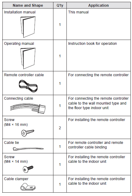
ELECTRICAL REQUIREMENT
| Conductor size | Type | Remarks | |
| Remote controller cable | 0.33 mm2 (22AWG) | Polar 3 core | Use sheathed PVC cable |
SELECTING AN INSTALLATION LOCATION
Dimensions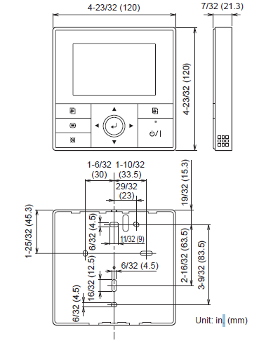
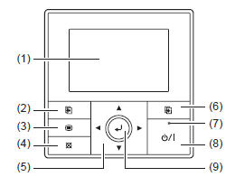
Name of parts
- Display panel (with backlight)
- Screen switch button (Left)
- Menu button
- Cancel button
- Cursor button
- Screen switch button (Right)
- Power indicator
- On/Off button
- Enter button
INSTALLING THE REMOTE CONTROLLER
Wiring
- Before starting installation work, turn off the power of the connection destination.
- Do not turn on the power again until installation is completed.
Otherwise, it will cause electric shock or fire. - Use the accessories or specified connection cables.
Do not modify connection cables other than those specified, do not use extension cords, and do not use independent branch wiring. - The allowable current will be exceeded and cause electric shock or fire.
Install the connection cables securely to the terminal block. - Confirm that external force is not applied to the wire.
- Use connection cables made of the specified wire.
- If intermediate connection or insertion fixing are imperfect, it will cause electric shock, fire, etc.
- Do not connect functional earthing to a telephone functional earthing, water pipe, or conductor rod.
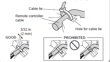
- Always fasten the outside covering of the connection cable with the cable clamp. (If the insulator is chafed, electric leakage may occur.)
- When performing cable wiring work, be sure that it does not touch the user. Doing so will cause injury or electric shock.
- If any cable is damaged, do not repair or modify it yourself. Improper work will cause electric shock or fire.
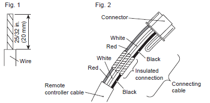
Connection of remote controller cable
When connecting to the wall mounted type and the floor type connector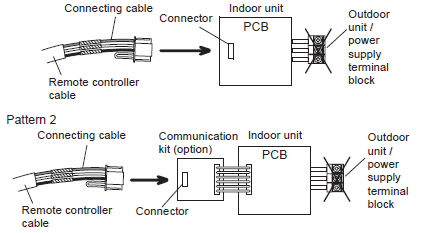
Modify the cable as per below methods.
- Use a tool to cut off the terminal on the end of the remote controller cable and then remove the insulation from the cut end of the cable as shown in Fig. 1.
- Connect the remote controller cable and connecting cable as shown in Fig. 2.
- Be sure to insulate the connection between the cables.
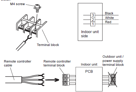
When connecting to the exclusive terminal block
Installation
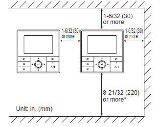
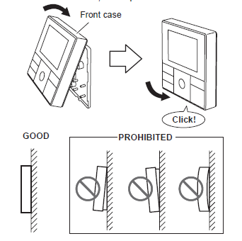
Installation space
- This product cannot be installed in wall.
- Recommendation installation height of the remote controller is 4.6ft. (1.4 m) (from the floor surface to the bottom of the remote controller).
- Even when you install a remote controller to one of a switch box and the surface of a wall, secure the space shown in following figure. If spaces run short, it will become difficult to remove a remote controller
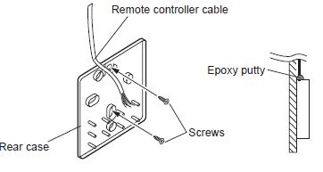
Processing of the remote controller cable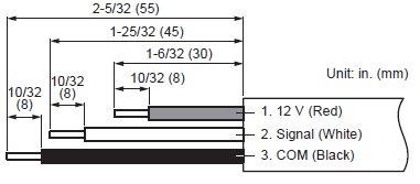
Remove the front case
- Insert the flat screwdriver and remove the front case and rear case by twisting it slightly.
- Hooks (2 places
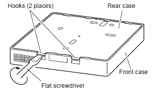
- Hooks (2 places
Installing the remote controller
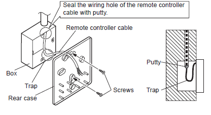
A. When attaching to switch box:
- Seal the wiring hole of the remote controller cable.
- Put a remote controller cable through the hole of the rear case.
- Fix the rear case by securing it with attached screws (2 places).
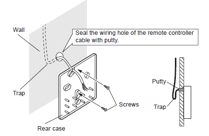
When attaching to the wall directly:
- Seal the wiring hole of the remote controller cable.
- Put a remote controller cable through the back hole of the rear case of the main body.
- Fix the rear case by securing it with attached screws (2 places).
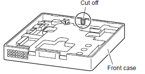
When routing the cable on-wall:
- Cut off the cable guide of the front case with using a knife or a nipper.
- Deburr the edge of the cable guide
 Fix the rear case by securing it with attached screws (2 places).
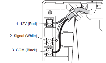
 Connect the cable to the terminals
| Tightening torque | |
| Terminal screw | 7.1 to 10.6 lbf•in (0.8 to 1.2N • m) |
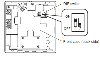
Setting the DIP switch
Memory backup setting
- If the DIP switch No. 1 is not set to ON, the settings information will be lost if there is a power failure.
- Registered information, such as that for the internal unit, is not erased even if the DIP switch is turned off.
|
No. |
Switch state |
Detail |
||
| OFF | ON | |||
|
DIP switch |
1 |
Invalidity |
Validity |
Memory backup setting
* Set to ON to use batteries for the memory backup. If batteries are not used, the settings information stored in memory will be deleted if there is a power failure. |
|
2 |
Dual remote controller setting
* Refer to “6.2. Dual remote controllers”. |
|||
Attach the front case
- Insert after adjusting upper part of front case.
- When insert the front case, do not pinch the cable.
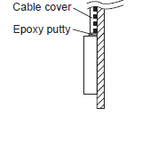
When routing the cable on top of the front case:
- Seal the cable guide of the front case of the remote controller cable with an epoxy putty.
- Thickness of sheath of the remote controller cable should be thicker than 1/32 in. (1 mm) or more. Or insulate it with a cable cover thicker than 1/32 in. (1 mm) or more
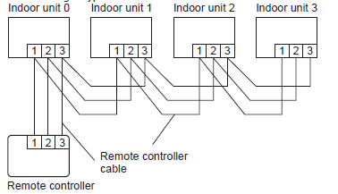
Group control
- A number of indoor units can be operated at the same time using a single remote controller.
- Depending on the model, some indoor units cannot be connected for group control. (Group control is available for the duct type, the cassette type, and the ceiling type indoor unit.)
- Some functions may become unusable, depending on the combination of the indoor units that are connected in a group.
- (1) Wiring method (indoor unit to remote controller)
- EXAMPLE: Single Type
Dual remote controllers
- Field setting can be performed only on the primary unit.
- Assignment of primary unit and secondary unit is necessary. No assignment will cause an error.
- Depending on the model, some indoor units cannot be connected for dual remote controllers. (Dual remote controllers are available for the duct type, the cassette type and the ceiling type indoor unit.)
- Two separate remote controllers can be used to operate the indoor units.
- The timer and functions cannot be used on the secondary units. (For the details, refer to the operating manual.)
- Wiring method (indoor unit to remote controller)
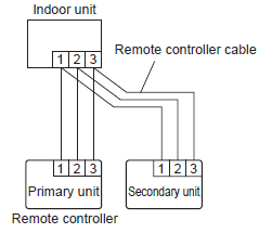
- Set the remote controller DIP switch No. 2 according to the following table.
| Number of remote controllers | Primary unit | Secondary unit |
| DIP Switch No. 2 | DIP Switch No. 2 | |
| 1 (Normal) | OFF | – |
| 2 (Dual) | OFF | ON |
TURNING ON THE POWER
- Check the remote controller wiring and DIP switch settings.
- Install the front case. (in 5. INSTALLING THE REMOTE CONTROLLER).
- Check the indoor and outdoor unit wiring and circuit board switch settings, and then turn on the indoor and outdoor units. After message
- “Please wait” is displayed on the remote controller display, “Language” screen is displayed
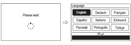
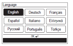
INITIAL SETTING
- Select a language with the [Cursor button] on the “Language” screen displayed when the start-up is completed
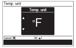
- Switch the unit for temperature “°C” or “°F” with [Cursor button (Up/ Down)].
- When [Cancel button] is pressed, it returns to the “Language” screen
- Set the display format of “Date format” and “Time format”.
- Switch the setting item with [Cursor button (Left/Right)] and confirm with the [Cursor button (Up/Down)].
- When [Cancel button] is pressed, it returns to the “Temp. unit” screen.
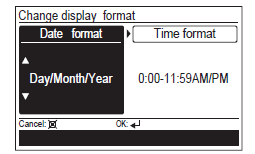
Note–
- Date format : Time format:
- Day/Month/Year 0:00-23:59
- Month/Day/Year 0:00-11:59 AM/PM
- Year/Month/Day 12:00-11:59 AM/PM
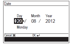
When [Enter button] is pressed, the “Date” screen is displayed.
- Set the “Day”, “Month”, and “Year”. Switch the setting item with [Cursor button (Left/Right)], and adjust with [Cursor button (Up/Down)]. When [Cancel button] is pressed, it returns to the “Change display format” screen
- Set the “hour” and “min”. Switch the setting item by [Cursor button (Left/Right)], and adjust with [Cursor button (Up/Down)]. “Min” can be set quickly if the button is pressed continuously.
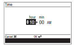
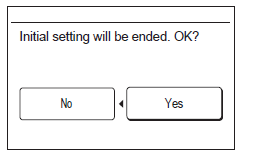
- When [Cancel button] is pressed, it returns to the “Date” screen. When setting is completed, select “Yes” with [Cursor button (Left/ Right)], and press [Enter button]. When correcting a setting, set it again as it returns to the “Language” screen when “No” is selected and press [Enter button].
SERVICE SCREEN SETTING
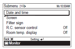
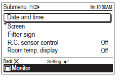
When [Menu button] is pressed twice while “Monitor” screen is displayed, it switches to the “Submenu” screen. Press the [Screen switch button (Left)] and [Screen switch button (Right)] simultaneously for 5 seconds to switch to “Service” screen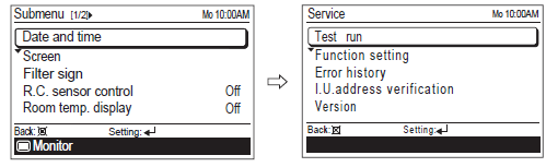
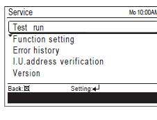
Service screen
|
Function name |
Setting | |
| Primary unit | Secondary unit | |
| Test run | ||
| Function setting | ||
| Error history | ||
| I.U.address verification | ||
| Version | ||
Test run
- When [Menu button] is pressed twice while “Monitor” screen is displayed, it switches to the “Submenu” screen.
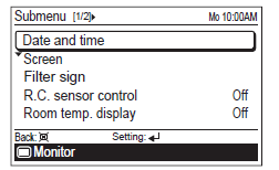
- If [Menu button] is pressed while the “Submenu” screen is displayed, the display returns to the “Monitor” screen.
- Press the [Screen switch button (Left)] and [Screen switch button (Right)] simultaneously for 5 seconds to switch to “Service” screen.
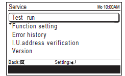
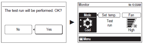
- When you select [Test run] with the [Cursor button (Up/Down)] and press the [Enter button], following confirmation screen is displayed.
- To start the test run, select “Yes” with the [Cursor button (Left/Right)], and press the [Enter button].
- In Set temp, test run is displayed.
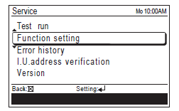
Function setting
- When [Menu button] is pressed twice while “Monitor” screen is displayed, it switches to the “Submenu” screen.
- If [Menu button] is pressed while the “Submenu” screen is displayed, the display returns to the “Monitor” screen
- Press the [Screen switch button (Left)] and [Screen switch button (Right)] simultaneously for 5 seconds to switch to “Service” screen.
- Select [Function setting] with pressing the [Cursor button (Up/Down)], and press the [Enter button].
- Select [R.C. address] of the target indoor unit with pressing the [Cursor button (Up/Down)]. (R.C. Address : Remote Controller Address)
- Select the [Function No.] with pressing the [Cursor button (Left/ Right)], and select the Function No. to be set with pressing the [Cursor button (Up/Down)].
- Select the [Setting No.] with pressing the [Cursor button (Left/Right)], and select the Setting No. to be set with pressing the [Cursor button (Up/Down)],and press the [Enter button].
Error history
I.U. address verification
The refrigerant address and the indoor unit address can be displayed. Select [I.U. address verification] with the [Cursor button (Up/Down)], and press the [Enter button].
Version
Software version of the remote controller can be displayed. Select [Version] with the [Cursor button (Up/Down)], and press the [Enter button].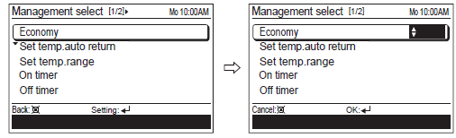
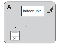
SETTING THE ROOM TEMPERATURE DETECTION LOCATION
Indoor unit setting (factory setting)
- The room temperature is detected by the indoor unit temperature sensor.
- When use this function, set “Indoor room temperature sensor switching function (Function Number:42)” of “9.2. Function setting” to “No(00)”.
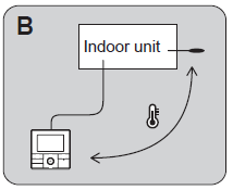
Indoor unit/remote controller setting (room temperature sensor selection)
- The temperature sensor of the indoor unit or the remote controller can be used to detect the room temperature.
- When use this function, set “Indoor room temperature sensor switching function (Function Number:42)” of “9.2. Function setting” to “Yes(01)”.
- Enable the room temperature sensor selection in function setting, which will be described later.
- Select either of the temperature sensor on the indoor unit or on the remote controller for temperature detection. (For how to configure the setting, refer to “5-5. R.C. sensor control” in the operating manual.)
Indoor room temperature sensor switching function
| Setting Description | Function No. | Setting No. |
| No |
42 |
00 |
| Yes | 01 |
Setting record
| Setting Description | Setting No. |
| Room temperature sensor switching |
MANAGEMENT FUNCTION
Restricts the operations of following power-saving functions by non-authorized person, and helps more energy-efficient operation of the system. With the password control, only the administrator can get access to the function setting. For the controlled functions, perform the setting change in “Management function” screen.
Settings Items:
- Function
- Economy
- Set temp. auto return
- Set temp. range
- Timer
- On timer
- ff timer
- Weekly timer
- Auto-off timer
(Set temp. auto return : Set temperature auto return) (Set temp. range : Set temperature range) For the details on each function, refer to “2-2. Setting items in Menu” in the operating manual.
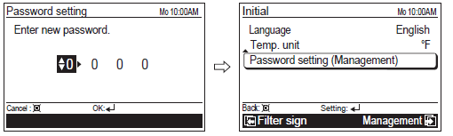
Password setting
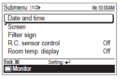
- When [Menu button] is pressed twice while “Monitor” screen is displayed, it switches to the “Submenu” screen.
- If [Menu button] is pressed while the “Submenu” screen is displayed, the display returns to the “Monitor” screen.
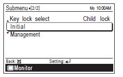
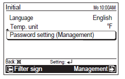
- When [Initial] is selected in [Submenu] screen, “Initial” screen is displayed. Enter current password with the [Cursor button], and press the [Enter button].
- Select [Password setting (Management)] in the “Initial” screen, and press the [Enter button].
- Enter current password.
- With pressing the [Cursor button (Up/Down)], enter the number. When you press the [Cursor button (Right)], the cursor moves to next digit.
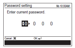
- After you enter the 4 digits, press the [Enter button].
- Enter new password with same procedure in step 4.
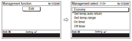
Management setting
- When [Menu button] is pressed twice while “Monitor” screen is displayed, it switches to the “Submenu” screen.
- If [Menu button] is pressed while the “Submenu” screen is displayed, the display returns to the “Monitor” screen.
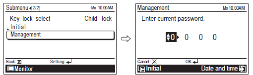
- When [Management] is selected in [Submenu] screen, “Management” screen is displayed. Enter current password with the [Cursor button], and press the [Enter button].
- If there is another setting to be changed, you can continue the configuration.
- To complete the setting, press the [Cancel button].
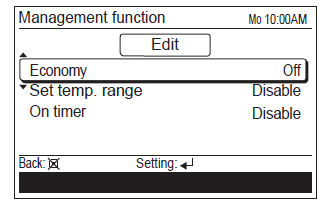
- Functions marked check in “Management select” screen are listed in “Management function” screen
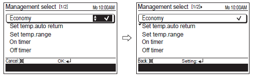
- In “Management function” screen, you can change the detailed setting on each function.
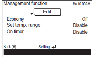
- For how change the setting, refer to each function setting in “3. FUNCTION SETTING” in the operating manual.
OTHERS
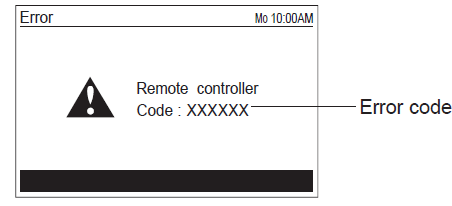
Error code
- If an error occurs, the power indicator (green) blinks and the following display will be shown.
- If “Error” is displayed, immediately stop the air conditioner operation, and consult authorized service personnel.
- When there is an error on this remote controller:
| Error code | Contents |
| Er 12.1 EE 1c | • Wired remote controller communication error |
|
Er 15.4 EE 1d |
• Incompatible indoor unit is connected
• Indoor unit date acquisition error • Primary unit / Secondary unit setting error |
| Er CC.1 EE CC.1 | • Remote controller sensor error |
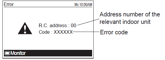
- When there is an error on the indoor unit:
Reference
Download Manual
Fujitsu UTY-RVNUM Wired Remote Controller Thermostat Installational Manual
Other Manual
Fujitsu UTY-RVNUM Wired Remote Controller Thermostat Operational Manual
Fujitsu UTY-RVNUM Wired Remote Controller Thermostat Product Specifications Guide
![]()
Fujitsu UTY-RVNUM Wired Remote Controller Thermostat Installational Manual