Fujitsu UTY-RNRUZ5 Wired Remote Thermostat

SAFETY PRECAUTIONS
- The “SAFETY PRECAUTIONS” indicated in the manual contain important information pertaining to your safety. Be sure to observe them.
- For details of the operation method, refer to the operation manual.
- Request the user to keep the manual on hand for future use, such as for relocating or repairing the unit.
WARNING Indicates a potentially or imminently hazardous situation which, if not avoided, could result in death or serious injury.
- Installation of this product must be done by experienced service technicians or professional installers only in accordance with this manual. Installation by nonprofessional or improper installation of the product may cause serious accidents such as injury, water leakage, electric shock, or fi re. If the product is installed in disregard of the instructions in this manual, it will void the manufacturer’s warranty.
- Installation must be performed in accordance with regulations, codes, or standards for electrical wiring and equipment in each country, region, or the installing place.
- Do not operate this unit when your hands are wet. Touching the unit with wet hands will cause an electric shock.
- When children can approach the unit or touch the unit, take preventive measures.
- Dispose of the packing materials safely. Tear and dispose of the plastic packing bags so that children cannot play with them. There is the danger of suffocation if children play with the original plastic bags.
CAUTION Indicates a potentially hazardous situation that may result in minor or moderate injury or damage to property.
- When detecting the room temperature using the remote controller, set up the remote controller according to the following conditions. If the remote controller is not well set, the correct room temperature will not be detected, and thus the abnormal conditions like “not cool” or “not heat” will occur even if the air-conditioner is running normally.
- A location with an average temperature for the room being air conditioned.
- Locate where is not be affected by infl ow of outside air such as caused by opening and closing a door.
- Not directly exposed to the outlet air from the air conditioner.
- Out of direct sunlight.
- Away from the influence of other heat sources.
Do not install the unit in the following areas:
- Do not install the unit near a source of heat, steam, or fl flammable gas. Otherwise, fi re could result.
- Area filled with mineral oil or containing a large amount of splashed oil or steam, such as a kitchen. It will deteriorate plastic parts, causing the parts to fall.
- Area containing equipment that generates electromagnetic interference. It will cause the control system to malfunction, and cause erroneous operation.
- Install the unit in a well-ventilated place avoiding rains and direct sunlight.
- Do not touch the switches with sharp objects. Doing so will cause injury, trouble, or electric shock.
- Do not expose this unit directly to water. Doing so will cause trouble, electric shock, or heating.
- Do not set vessels containing a liquid on this unit. Doing so will cause heating, fi re, or electric shock.
MAIN UNIT AND ACCESSORIES
The following installation parts are supplied. Use them as required.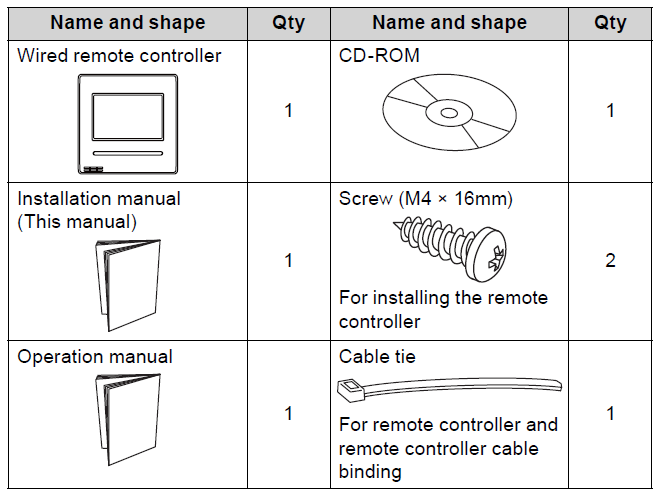
ELECTRICAL REQUIREMENT
When connecting the remote controller use the following wiring.
| Cable size | Wire type | Remarks |
| 22 to 16 AWG
(0.33 to 1.25 mm²) |
Non polar 2 core | Use sheathed twisted pair cable |
| 18AWG | Thermostat cable 2 core | Use sheathed non twisted pair cable |
Select a fl exible cable that can be bound using cable ties from over the cable sheath inside this unit. Maximum connectable number of remote controllers by cable size and the length.
| Cable size | Max. connectable number of remote controllers | ||||||
|
AWG |
mm² |
L* ≤ 328 ft (L* ≤ 100 m) |
328 ft < L*
≤ 820 ft (101 m < L* ≤ 250 m) |
820 ft < L*
≤ 1,640 ft (251 m < L* ≤ 500 m) |
|||
| VRF | RAC | VRF | RAC | VRF | RAC | ||
| 16 | 1.25 | 4 | 2 | 4 | 2 | 4 | 2 |
| 18 | 0.75 (1.25 > S* ≥ 0.75) | 4 | 2 | 4 | 2 | 2 | 2 |
| 20 | 0.5 (0.75 > S* ≥ 0.5) | 4 | 2 | 2 | 2 | 2 | 2 |
| 22 | 0.3 (0.5 > S* ≥ 0.3) | 4 | 2 | 1 | 1 | 1 | 1 |
L: Total cable length, *S: Cable size
SELECTING AN INSTALLATION LOCATION
Dimensions and Name of parts
Remote controller unit
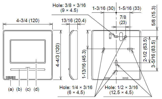
- Room temperature sensor (inside)
- Operation (Ocupied/Unoccupied) button:
It is possible to operate only while displaying the Monitor Mode screen. - LED lamp (Operation indicator)
- Touch panel display
All Fujitsu General products are manufactured to metric units and tolerances. United States customary units are provided for reference only.
In cases where exact dimensions and tolerances are required, always refer to metric units.
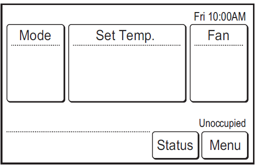
Monitor mode screen
The home screen of this unit. Except for in the following cases, the screen will return to this screen if there is no operation for over 10 min. (Unsaved settings will be cancelled.)
- In Emergency Stop.
- In Transferring data.
- In checking the indoor unit position
- In Function Setting
- In Vacation

- (a) R.C. Group name: Refer to 6.3.4. If “Lead-Lag” is displayed, refer to 6.3.13.
- (b) Clock: Refer to 6.2.4.
- (c) Mode: Set the operation mode. Refer to operation manual.
- (d) Set Temp.: Set the operation temperature. Refer to operation manual.
- (e) Fan: Set the fan speed. Refer to operation manual.
- (f) Away: When “Away” is enabled, the start temperature of “Away” operation is displayed when unoccupied. When “away” is operating, “Away Operation” is displayed. Refer to the operation manual.
- (g) Room temperature: Refer to 4.2. and 6.3.5.
- (h) Override: Displayed while the following functions are operating:
- Auto Off Timer
- Set Temp. Auto Return Refer to operation manual.
- (i) Occupied state: “Occupied” or “Unoccupied” is displayed according to the operation of Operation button or schedule setting. In the following cases, the operation button needs to be pressed twice:
- When stopping the operating indoor unit while “Unoccupied” is displayed, press the operation button once to set to “Occupied” and press it again to set to “Unoccupied”. Then the indoor unit stops.
- When operating the stopped indoor unit while “Occupied” is displayed, press the operation button once to set to “Unoccupied” and press it again to set to “Occupied”. Then the indoor unit operates.
- In the following cases, the occupied state does not switch to “Occupied” even if the indoor unit starts operation:
- Anti freeze operation
- Away operation
- Optimum start operation
- (j) Menu: Set the various settings. Refer to operation manual.
- (k) Status: Check the status of indoor unit and error.
- (l) Vacation: When this is touched, the schedule is disabled and the indoor unit remains unoccupied. “Vacation” is displayed only when a schedule is set. Refer to operation manual.
- (m) “Custom Auto Mode” or “Away” does not work.
Verify the following settings:- R.C. Sensor Setting: Refer to 6.3.5.
- Master Indoor Unit Setting: Refer to 6.3.6.
When the remote controller that uses a sensor is changed in the master indoor unit or R.C. Group, change the operation mode or disable “Away”.
- (n) Status icons: Refer to operation manual.
For the screen display, this product uses a Bitmap font made and developed by Ricoh Company, Ltd.
Setting the room temperature detection location
CAUTION As the temperature sensor of remote controller detects the temperature near the wall, when there is a certain difference between the room temperature and the wall temperature, the sensor will not detect the room temperature correctly sometimes. Especially when the outer side of the wall on which the sensor is positioned is exposed to the open air, it is recommended to use the temperature sensor of the indoor unit to detect the room temperature when the indoor and outdoor temperature difference is significant.
The detection location of the room temperature can be selected from the following 2 methods. Choose the detection location that is best for the installation location.
The temperature sensor of the indoor unit or the remote controller can be used to detect the room temperature.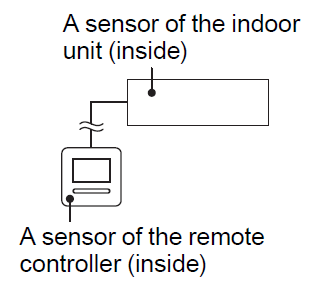
When the remote controller is not used, the following functions cannot be used.
- [Custom Auto] of the operation modes: Refer to operation manual.
- [Away Setting]: Refer to operation manual.
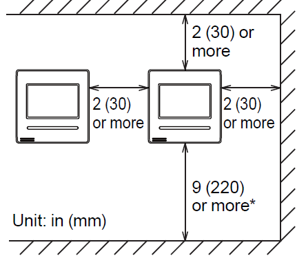
Installation space
- Do not embed this remote controller in a wall.
- Recommendation installation height of the remote controller is 55 in (1.4m) (from the floor surface to the bottom of the remote controller).
- Even when you install a remote controller to one of a switch box and the surface of a wall, secure the space shown in following figure. When there is insufficient space, there may be remote controller sensor misdetections and remote controller removal may be difficult.
- Secure enough space where a fl at-blade screwdriver to take off a case can be inserted.
INSTALLING THE REMOTE CONTROLLER
WARNING
- Always use the accessories and specifi ed installation work parts. Check the state of the installation parts. Not using the specifi ed parts will cause units to fall off , water leakage, electric shock, fi re, etc.
- Install at a place that can withstand the weight of the unit and install firmly so that the unit will not topple or fall.
- When installing this unit, make sure that there are no children nearby. Otherwise, injury or electric shock could result.
- Before starting installation work, turn off the power of this unit and the connection destination. Do not turn on the power again until installation is completed. Otherwise, it will cause electric shock or fire.
- Use the accessories or specifi ed connection cables. Do not modify connection cables other than that specifi ed, do not use extension cords, and do not use independent branch wiring. The allowable current will be exceeded and cause electric shock or fire.
- Install the remote controller cables securely to the terminal block. Confirm that external force is not applied to the cable. Use remote controller cables made of the specifi ed wire. If intermediate connection or insertion fi xing are imperfect, it will cause electric shock, fire, etc.
- When connecting the remote controller cable, route the cables so that the rear case of this unit is securely fixed. If the rear case is imperfectly fixed, it may cause fi re or overheating of the terminals.
- Perform functional earthing work positively. Do not connect the functional earthing wire to a telephone ground (earth) wire, water pipe, or conductor rod.
- Always fasten the outside covering of the connection cable with the cable tie. If the insulator is chafed, electric discharge may occur.
CAUTION
- Do not set the DIP switch or rotary switch of this unit except as specifi ed in this manual or the operation manual supplied with the air conditioner. Setting the switches other than specifi ed will cause an accident or trouble.
- Before opening the case of this unit, completely discharge static electricity charged on you body. Not doing so will cause trouble.
- Do not touch the circuit board and circuit board parts directly with your hands. Otherwise, injury or electric shock could result.
- Be careful so that the front case does not fall after the front case screws are removed. Otherwise, injury could result.
- Install the remote controller cables 1 m away from television and radio to avoid distorted images and noise.
- Confi rm the name of each terminal block of the unit and connect the wiring in accordance with the directions given in the manual. Improper wiring work will damage the electric parts and cause smoke and fire.
- Connect the connectors securely. Loose connectors will cause trouble, heating, fi re, or electric shock.
- Never bundle the remote controller cables , the power supply cable and transmission cable together. Bundling these cables together will cause miss operation.
- When installing the connection cable near a source of electromagnetic waves, use shielded cable. Otherwise, a breakdown or malfunction could result.
Wiring types
Single control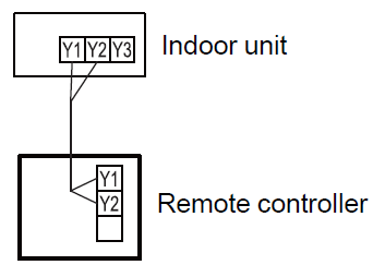
Group control
With a single remote controller, up to 16 units can be simultaneously operated.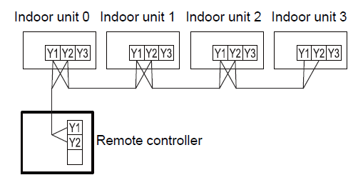
Multiple remote control
Number of connectable remote controllers. VRF: 4, RAC: 2
Multiple installation method described above is prohibited to combine 3 Wired type with 2 Wired Type.
In multiple installations, the following functions are restricted. Functions that can only be used with a Master Remote Controller:
- Auto Off Timer Setting *1
- Weekly Timer Setting *1
- Set Temp. Auto Return *1
- 6.3.11 Optimum Start Setting
- 6.4.7 I.U. Address Verifi cation
- 6.4.8 Function Setting
(*1 : Refer to operation manual)
Group control and multiple remote control can be used together.
Preparing for Installation
Strip of the remote controller cable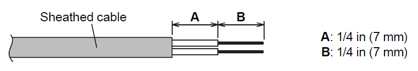
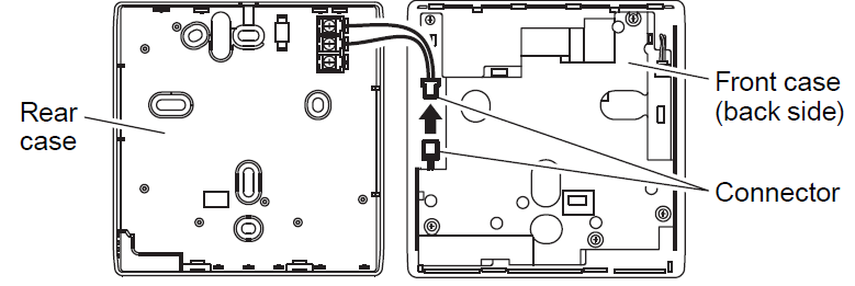
Remove the front case
When opening the remote controller, remove the connector from the front case. The cables may break if the connector is not removed and the front case hangs down. When installing the front case, connect the connector to the front case. When removing and connecting the connector, be careful not to break the cables.
Release the claws (2 places) with a fl at-blade screwdriver, and separate the front case and rear case.

Disconnect the connection cable connector from the connector of the front case PC board (printed circuit board).
Setting the DIP switch
CAUTION Use an insulated screwdriver to set the DIP switches. Do not touch the DIP switch with your hands.

Before using this product, always set DIP switch to “ON”. If not set, when the main power is turned on again, the set data by menu operation will be erased and cause erroneous operation.
[DIP Switch]
- Performs the enabling/disabling of the backup function by the internal battery.
- It is disabled when shipped from the factory to prevent consumption of the charge.
Installation
CAUTION Perform wiring so that water does not enter this unit along the external wiring. Always install a trap to the wiring or take other countermeasures. Otherwise it will cause trouble or electric shock or fire.
Install the rear case
A. When attaching to switch box:

B. When attaching to the wall directly:

C. When routing the cable on-wall:
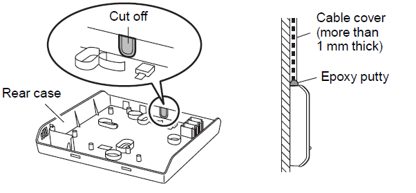
Connecting the remote controller cable
CAUTION When connecting a remote controller cable to the remote controller terminal block, use the specifi ed torque to tighten screws. If you over-tighten screws, they will break the terminal unit.
Be careful to avoid breaking the cable by over-tightening the cable tie.
- Tightening torque: 7.1 to 10.6 lbf•in (0.8 to 1.2 N•m)
Fasten the outside covering of the connection cable with the cable tie. Tighten the cable tie firmly so that pulling force does not propagate to the terminal connection even if force of 30 N is applied to the cable.
Select a flexible cable that can be bound using cable ties from over the cable sheath inside this unit.

Attach the front case
Connect the remote controller cable connector to the connector of the front case PC board. Insert after adjusting upper part of front case. Otherwise, there is a risk of damage to the internal parts of this unit. When you attach the front case, make sure that the cables are not being pinched by front case.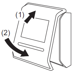
Connecting to the indoor unit
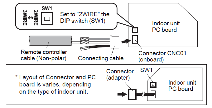
CAUTION When connecting the remote controller cable to the indoor unit, do not connect it to the outdoor unit or the power terminal block. It may cause a failure. When switching the DIP switch (SW1) on the indoor unit PC board, be sure to turn off the power supply to the indoor unit. Otherwise, the PC board of the indoor unit may be damaged.
There are 2 methods to connect the remote controller cable to the indoor unit. One is the connection using connecting cable (Included in the indoor unit), and the other is the connection the remote controller cable is connected to the exclusive terminal block of the indoor unit.
(For the details, refer to the installation manual of the indoor unit to be used.)
When connecting to the connector
- Use a tool to cut off the terminal on the end of the remote controller cable, and then remove the insulation from the cut end of the cable as shown in Fig. 1. Connect the remote controller cable and connecting cable as shown in Fig. 2. Be sure to insulate the connection between the cables.
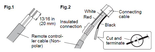
- Connect the remote controller cable to the connecting cable, and insert it to the connector. Set to “2WIRE” the DIP switch (SW1) on the PC board of the indoor unit.
When connecting to exclusive terminal block
- Connect the end of remote controller cable directly to the exclusive terminal block. Set to “2WIRE” the DIP switch (SW1) on the PCB (printed circuit board) of the indoor unit.
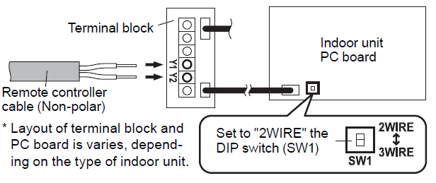
| Tightening torque | |
| M3 screw
(Remote controller / Y1, Y2) |
4.4 to 5.3 lbf·in (0.5 to 0.6 N·m) |
For “Group control” or “Multiple remote control”, refer to the following figure on how to connect to the indoor unit terminal.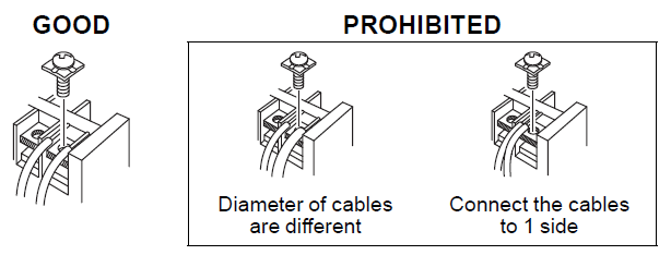
SETTING THE REMOTE CONTROLLER
Initialization procedure
After remote controller installation work is complete, perform initialization using the following procedures before starting to use the system.
(*: Items that indoor unit does not support are not displayed.)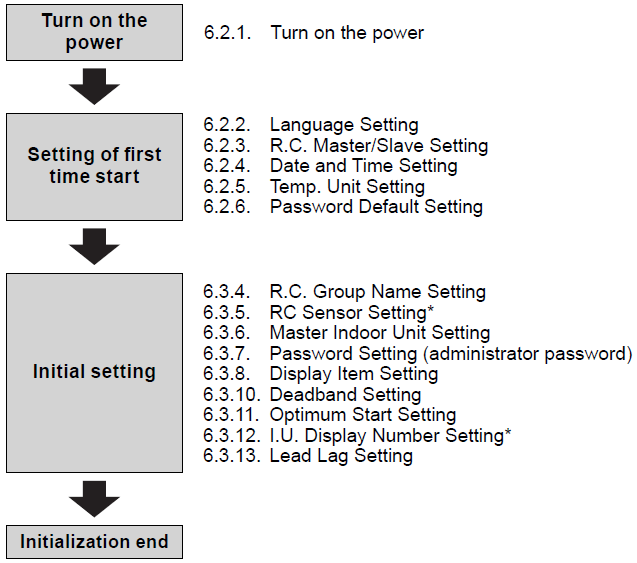
After installing this unit, perform the test run to confirm that the unit is operating properly. Then, explain the operation of this unit to the customer.
Setting of first time start
Turn on the power
CAUTION: Recheck the wiring. Incorrect wiring will cause trouble. When initially starting up this unit, the following setting screen will be displayed. Settings confi gured at this stage can be changed afterwards.
- If an error screen is displayed, shut down all unit power, and check the connections. After resolving the problem, turn on the power again.

- If “Please set the address correctly.” is displayed, touch [Close], and the “RC Ad-dress Setting” screen (refer to 6.4.6) will be displayed. After setting, restart this unit.

Language Setting
- The “Language Setting” screen has two pages. You can switch be-tween the pages by touching [Next Page] or [Previous Page]. Touch the language to be used.
Touch [OK] to Language Setting Page 1/ 2 Language Setting Page 2/ 2 display the “R.C. English Français Deutsch Italiano Português Türkçe Master/ Slave Setting” screen.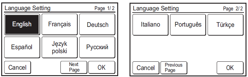
R.C. Master/Slave Setting
- (a) If the remote controller is a single connection, this setting is omitted. Proceed to “6.2.4. Data and Time Setting”.
(b) If a remote controller has multiple connections, and if “Master” is initially set, all other units will be set to “Slave”. Set only one Master remote controller. Units other than Master are set to Slave automatically.
When remote controllers are set to “Slave”, setting items will be restricted.
Touch [OK] to display the “Date and Time Setting” screen.
Date and Time Setting
- Touch the [Date] on the “Date and Time Setting” screen. The “Date” screen is displayed.
- Touch
 to set the year, month, and date. Touch [OK] to return to the “Date and Time Setting” screen.
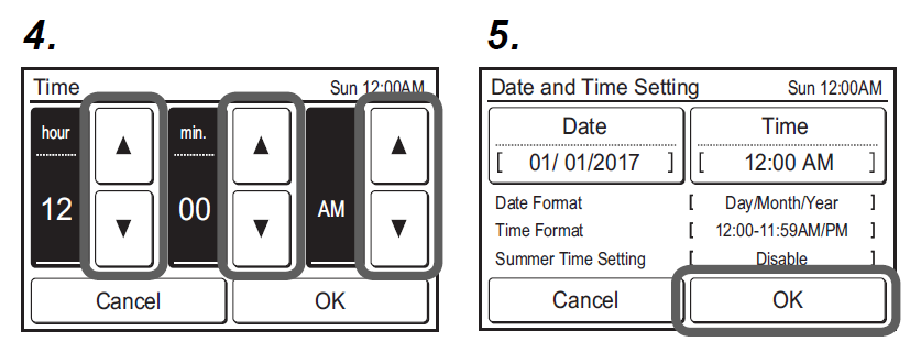
 - Touch the [Time] on the “Date and Time Setting” screen. The “Time” screen is displayed.
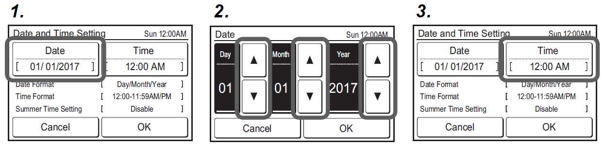
- Touch [ ] or [ ] to set hours, minutes, and AM/PM. Touch [OK] to return to the “Date and Time Setting” screen.
- Touch [OK] on the “Date and Time Setting” screen to display the “Temp. Unit Setting” screen.
Temp. Unit Setting
- Select and touch [°F] or [°C] and touch [OK].
- Touch [OK] on the “Temp. Unit Setting” screen to display the “Password Default Setting” screen.

Password Default Setting
- Select and touch [Enable] or [Disable] and touch [OK].
The initial value at “Change Setting” of “6.3.7 Password Setting” is diff erent depending on the selection of commercial use or residential use. Refer to the table below.
Function (*: Items that indoor unit does not support are not displayed.)
Enable (Commercial) Disable (Residential) Auto Off Timer On Off Weekly Timer On Off Set Temp. Auto Return On Off Set Temp. Range Setting On Off Anti Freeze* On Off Away Setting On Off Human Sensor Setting* On Off Fan Control for Energy Saving* On Off Initial Setting On Off Maintenance On Off - When initial start-up setting is complete, the screen on the right will be displayed. This screen is the “Monitor mode screen”, which is the home screen of this unit.
Initial setting
Configure settings required at the time of installation. This unit has two kinds of passwords; pass-word for administrators and password for installers. Password for administrators cannot be used for the settings related to the installation of this unit. Installer password can be used to configure all of setting for this unit.
When “Password (Installer Password) Verifi cation” screen is displayed, enter the password (installer password) and touch [OK]. The default password is “0000” (4 digits).
- Touch the [Menu] on the “Monitor Mode screen”. The “Main Menu” screen is displayed.
- The “Main Menu” screen has two pages. Touch [Next Page] or [Previous Page] to switch between screens. Touch the [Initial Setting].(Items that indoor unit does not support are not displayed.)
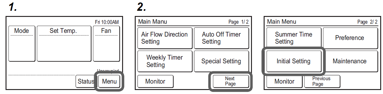
- The “Initial Setting” screen has three pages. Touch [Next Page] or [Previous Page] to switch between screens. Touch the items you wish to configure.
(Items that indoor unit does not support are not displayed.)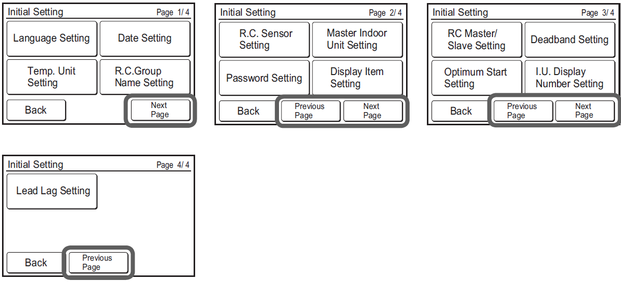 If “Lead Lag Setting” is not displayed, refer to “Lead Lag Setting” in the operation manual.
Language Setting
Touch the [Language Setting] on the “Initial Setting” screen. The “Language Setting” screen is displayed.
For the method of setting language, refer to 6.2.2. Language Setting. Select the language to be used, and touch [OK] on “Language Setting” to return to the “Initial Setting” screen.
Date Setting
- Touch the [Date Setting] on the “Initial Setting” screen. The “Date Setting” screen is displayed.
Select and touch “Date and Time Setting” or “Display Format Setting”.
When settings for all items are complete, the screen will return to the home screen. Touch [Back] to return to the “Initial Setting” screen.
Date and Time Setting
Touch the [Date and Time Setting] on the “Date Setting” screen. The “Date and Time Setting” screen is displayed.
For the method of confi guration, refer to 6.2.4. Date and Time Setting. Set all required items, and touch [OK] on the “Date and Time Setting” screen to return to the “Date Setting” screen.
Display Format Setting
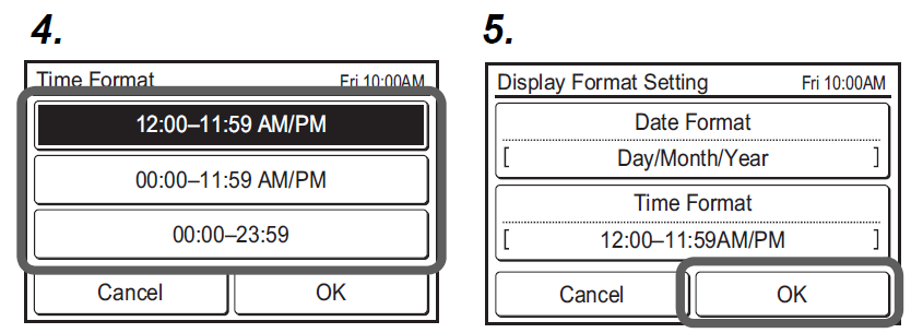
- Touch the [Date Format] on the “Display Format Setting” screen. The “Date Format” screen is displayed.
- Select and touch the data display format. Touch [OK] on the “Date Format” screen to return to the “Display Format Setting” screen.
- Touch the [Time Format] on the “Display Format Setting” screen. The “Time Format” screen is displayed.

- Select and touch the data display format. Touch [OK] on the “Time Format” to return to the “Display Format Setting” screen.
- Touch [OK] on the “Display Format Setting” screen to return to the “Date Setting” screen.
Temp. Unit Setting
Touch the [Temp. Unit Setting] on the “Initial Setting” screen. The “Temp. Unit Setting” screen is displayed.
For how to confi gure, refer to 6.2.5. Temp. Unit Setting. Set temperature units and touch [OK] on the “Temp. Unit Setting” to return to the “Initial Setting” screen.
R.C. Group Name Setting
Touch the [R.C. Group Name Setting] on the “Initial Setting” screen. The “R.C. Group Name Setting” screen is displayed.
About the “R.C. Group Name Setting” screen
Touch the relevant key and enter a name. Touch [OK] to return to the “Initial Setting” screen after dis-playing the “Confi rmation screen”.
- (a) Input area: If the number of input characters exceeds that permitted, “Over” will be displayed on the right side.
- Character keys: Touch the same key until the character you wish to use is displayed.
- Fixed Phrase key: Floor, Corridor, Offi ce, Conf Room, Recept Room, Room, Room No., Front, Side, Entrance, Outlet, East, West, South, North, Window are registered. Touch the [Fixed Phrase] key until the sentence you wish to use is displayed.
- (d) Space key
- (e) Backspace key
- (f) Cursor keys
RC Sensor Setting
- Touch the [RC Sensor Setting] on the “Initial Setting” screen. The “RC Sensor Setting” screen is displayed.
If a remote-control sensor is used, touch [Used]. Touch [OK] to return to the “Initial Setting” screen.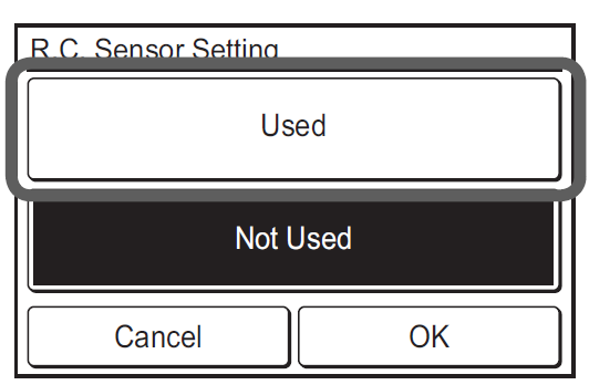
When set to [Not Used] by this setting, the following functions cannot be used: (Refer to the operation manual on the accessory CD-ROM.)
- Custom Auto in the operation mode. Refer to [2 CONTROL] → [2-2 Operation Settings] → [2-2-1 Set the Operation Mode].
- Away Setting. Refer to [3 SETTING] → [3-5 Special Setting] → [3-5-5 Away Setting].
- Optimum Start Setting. Refer to [3 SETTING] → [3-8 Initial Setting] → [3-8-9 Optimum Start Setting].
Master Indoor Unit Setting
- One of the multiple indoor units connected to the same refrigerant system or RB unit can be set as the “master unit”.
- The indoor unit defi ned as the “master unit” determines the priority mode (cool or heat) within the refrigerant system or RB group.
- Switch setting on the outdoor unit or RB unit that is connected to the indoor units. Refer to the installation manual of outdoor unit or RB unit.
- Touch the [Master Indoor Unit Setting] on the “Initial Setting” screen. The “Master Indoor Unit Setting” screen is displayed.
To set a unit as the Master Indoor Unit, touch [Set]. - Touch [Yes] when the confi rmation screen is displayed to return to the “Master Indoor Unit Setting” screen.
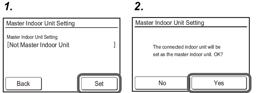
When changing the Master Indoor Unit, another indoor unit cannot be made the master indoor unit unless the settings of the current master indoor unit are cancelled beforehand.
(“Reset” cannot be performed while the indoor unit is operating.)
Password Setting (administrator password)
Set or change the administrator password.
- Touch the [Password Setting] on the “Initial Setting” screen. The “Password Setting” screen is displayed. Then touch the [Change Password] on the “Password Setting” screen. The “Change Password” screen is displayed.
- Enter the current password, then touch the [OK]. The default password is “0000” (4 digits).
- Enter the new password, then touch the [OK]. It returns to the “Password Setting” screen.

- Touch the [Change Setting] on the “Password Setting” screen. The “Change Setting” screen is displayed.
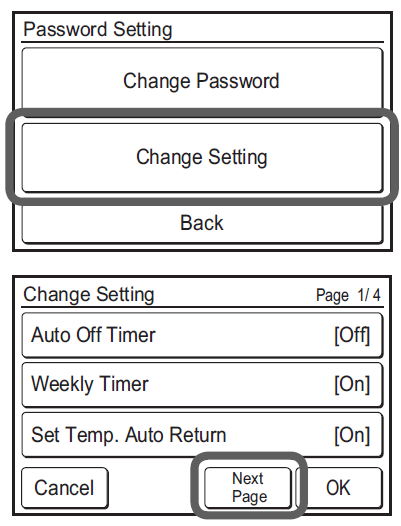
- The “Change Setting” screen is 3 or 4 pages, they can be switched by the [Previ-ous Page] or [Next Page]. Items set to be [On] require the administrator password to open the setting screen.

Items that indoor unit does not support are not displayed. - Touch the relevant item to display the setting screen. Touch [OK] after touching [On] to return to the “Change Setting” screen. Touch [OK] on the “Change Setting” screen after setting relevant items to return to the password setting screen.
- Touch the [Back] on the “Password Setting”. It returns to the “Initial Setting” screen.

Display Item Setting
Filter Sign Set to “Visible” to display icons on the “Monitor mode screen” during the indoor unit filter cleaning period.
- Touch the [Display Item Setting] on the “Initial Setting” screen. The “Display Item Setting” screen is displayed.
- Then touch the [Filter Sign] on the “Display Item Setting” screen. The “Filter Sign” screen is displayed. Touch [OK] after touching [Visible] or [Invisible] to return to the “Display Item Setting” screen.

Room Temp.
Set to “Visible” to display the room temperature detected by this unit on the monitor screen. - Touch the [Room Temp.] on the “Display Item Setting” screen. The “Room Temp.” screen is displayed.
- Touch [OK] after touching [Visible] or [Invisible] to return to the “Display Item Setting” screen.
- Touch the [OK] on the “Display Item Setting”. It returns to the “Initial Setting” screen.

RC Master/Slave Setting
If multiple remote controllers are set for a remote-control group or for a single indoor unit, it is necessary to set the remote-controller master. This setting will be required at the time of initial start-up during installation. However, this setting can be changed afterwards. No master remote controllers will be automatically set to be slaves. The following functions can be used with slave remote controllers.
For the method of configuration, refer to 6.2.3. RC Master Slave Setting. Setting. Touch [OK] on the “RC Master/Slave Setting” screen after setting the temperature units to return to the “Initial setting” screen.
Do not perform “RC Master/Slave Setting” during setting or operating from the Master unit.
Deadband Setting
- Touch the [Deadband Setting] on the “Initial Setting” screen. The “Deadband Setting” screen is displayed. “Deadband Setting” screen is displayed. Adjust the deadband with the .
When the [OK] is touched, the display returns to the “Initial Setting” screen.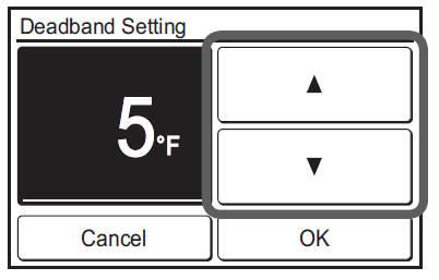
When the “Auto mode type” (No. 68) of the function setting on the indoor unit is set to “Dual set point”, deadband can not be set on this unit. (The Deadband Setting is not displayed.) Please set in the “Deadband value” (No. 69) of the function setting on the indoor unit.
Optimum Start Setting
- Touch the [Optimum Start Setting] on the “Initial Setting” screen. “Optimum Start Setting” screen is displayed. Select the [On] or [Off ].
When the [OK] is touched, the display returns to the “Initial Setting” screen.
I.U. Display Number Setting
At initial starting, the display numbers (Unit X) of the indoor units displayed at the “Individual VT Hold” setting of this remote controller are automatically allocated in ascending order of address value. (For the indoor unit display number (Unit X), refer to “3-2-3 Individual VT Hold” of the operation manual on the accessory CD-ROM )
The indoor units (corresponding addresses) can be rearranged in arbitrary order in which you want to correspond to the display number (Unit X) at this setting. Decide the indoor unit (address) corresponding to the display number (Unit X) by consulting the user.
- Touch the [I.U. Display Number Setting] on the “Initial Setting” screen.
- “I.U. Display Number Setting” screen is displayed. When the screen has multiple pages, they can be switched by touching the [Next Page] or [Previous Page]. The address (System-Unit) allocated to the current display number (Unit X) is displayed. The refrigeration system address (Ref.-in.) is displayed only when this remote controller is connected to a VRF system. Touch the display numbers (Unit X) whose address you want to interchange.
- The address selection screen is displayed. Select the address of the indoor unit you want to match to the display number selected at step 2 with .
When [OK] is touched, the display returns to the screen of 2 and the address is interchanged with the selected display number (Unit X). Repeat steps 2 and 3 up to the desired order.
When [Back] of the screen of 2 is touched, the display returns to the “Initial Setting” screen.
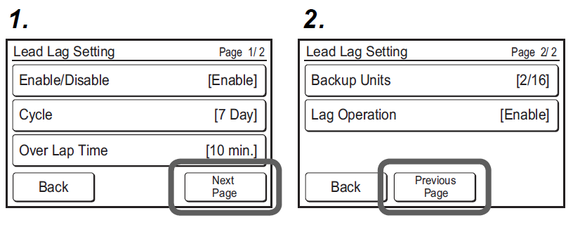
Lead Lag Setting
NOTE:
Be sure to read the operation manual of this product for detailed operating procedures and precautions. When enabling the rotation operation, the indoor units in the RC Group take turns stopping 1 or 2 at a time.
- Touch the [Lead Lag Setting] on the “Initial Setting” screen. The “Lead Lag Setting” screen is displayed.
- The screen has 2 pages which are switched by touching the [Next page] or [Previous Page].
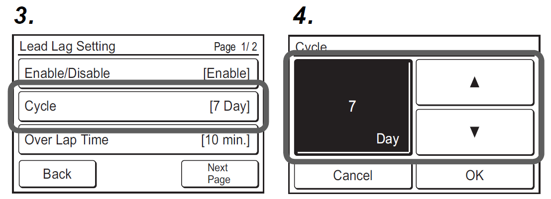
Cycle Setting3. - Touch the [Cycle] on the “Lead Lag Setting” screen.
- “Cycle” screen is displayed. Set the day by touching [ ] or [ ]. The day can be set “TEST” or from 1 day to 7 days in 1-day increments. Touch the [OK] to return to the “Lead Lag Setting” screen.
 NOTE:
NOTE:
When TEST is set and “Lead Lag Operation Enable/Disable” is set to “Enable”, the indoor units switch the operation/stop following the lead lag operation setting each time you press the [On/Off ] button.
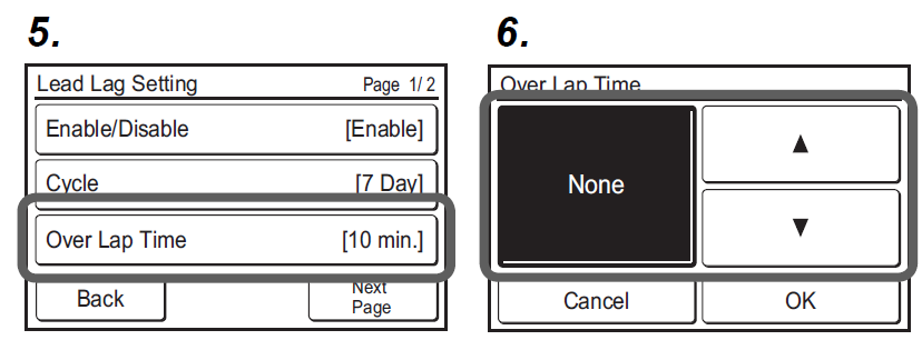
Overlap Time Setting - Touch the [Over Lap Time] on the “Lead Lag Setting” screen.
- “Over Lap Time” screen is displayed. Set the overlap time by touching [ ] or [ ]. The overlap time can be set “None” or from 10 minutes to 30 minutes in 10 minutes increments. When selecting “None”, the Rotation operation has no overlap time. Touch the [OK] to return to the “Lead Lag Setting” screen.
Backup Units Setting
Select the number of indoor units which stop simultaneously. - Touch the [Backup Units] on the “Lead Lag Setting” screen.
- “Backup Units” screen is displayed. Touch the [2 Units] or [1 Unit]. Touch the [OK] to return to the “Lead Lag Setting” screen.

NOTES:
If there are 2 connected indoor units, it is possible to set “1 Unit” only. When written as a fraction, the numerator (top) indicates the number of backups, and the denominator (bottom) indicates the total number.
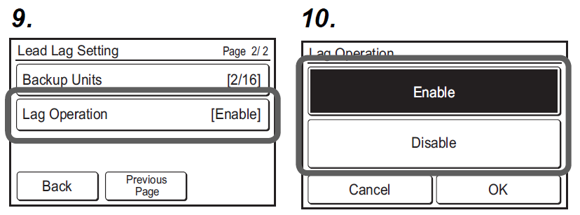
Lag Operation Setting
If the room temperature remains high while after starting the lead lag operation, the stopped indoor unit will start the operation. - Touch the [Lag Operation] on the “Lead Lag Setting” screen.
- “Lag Operation” screen is displayed. Touch the [Enable] or [Disable]. Touch the [OK] to return to the “Lead Lag Setting” screen.
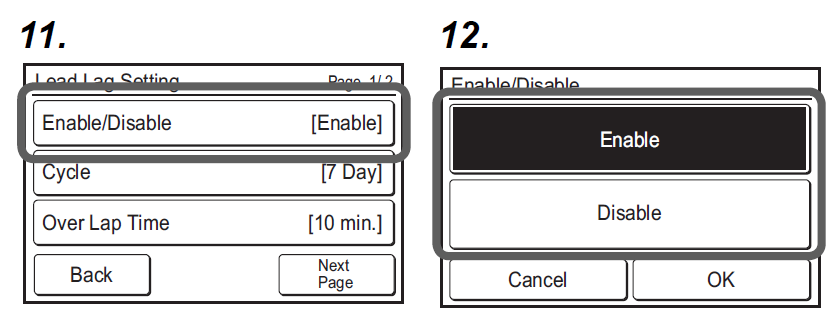
Lead Lag Operation Enable/Disable - Touch the [Enable/Disable] on the “Lead Lag Setting” screen. “Enable/Disable” screen is displayed. Touch the [Enable] or [Disable].
- When the [OK] is touched, the lead lag operation starts or stops. The display returns to the “Lead Lag Setting” screen.
Quit the Lead Lag Setting
Press [Back]. If set to “Enable”, the screen will return to Monitor mode screen (Lead Lag display). If set to “Disable”, the screen will return to “Initial Setting” screen.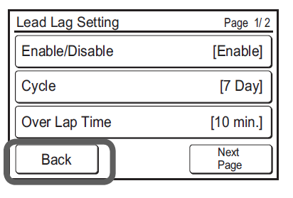
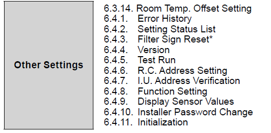
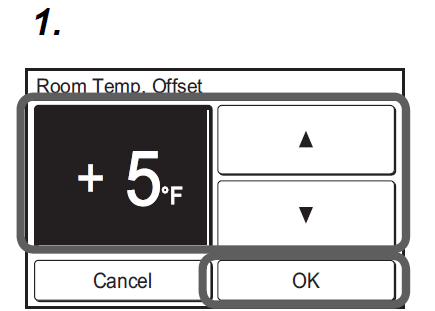
Room Temp. Off set Setting
- Uniformly corrects detection variations in the wired remote controller’s temperature sensor.
- Uniformly corrects differences between the actual temperature and the temperature detected by the wired remote controller.
NOTES:
The following situations where uniform correction is not possible are not covered under the warranty for room temperature correction.
- If a measurement variation between the temperature detected by the temperature sensor and the actual temperature around the wired remote controller occurs due to the effects of direct sunlight
- If a measurement variation between the temperature detected by the temperature sensor and the actual temperature around the wired remote controller occurs due to the effects of the wall temperature
- If a difference occurs between the temperature detected by the temperature sensor and the temperature in and around the center of the room due to the effects of air currents
- Hold the power button for 5 seconds or more on the “Initial Setting” screen. The “Room Temp. Off set” screen is displayed. Set the correction temperature by touching . The correction temperature can be set from -8 °F to 8 °F in 1 °F increments. Touch the [OK] to return to the “Initial Setting” screen.
Maintenance (Other Settings)
Carry out the following setting and confirmation, as required.
- Touch the [Menu] on the “Monitor mode screen”. The “Main Menu” screen is displayed.
- The “Main Menu” screen has two pages. Touch [Next Page] or [Pre-vious Page] to switch between screens. Then touch the [Maintenance]. (Items that indoor unit does not support are not displayed.)

- The “Maintenance” screen is displayed. The “Maintenance” screen has 3 pages. Touch [Next Page] or [Previous Page] to switch be-tween screens.
(Items that indoor unit does not support are not displayed.)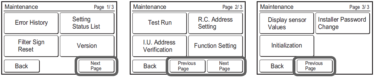
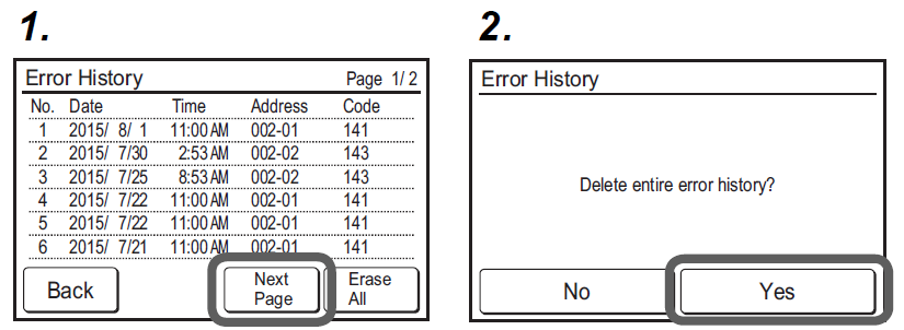
Error History
- Touch the [Error History] on the “Maintenance” screen. The “Error History” screen is displayed.
If there are 7 or more errors, you can switch between pages by touching [Next Page] or [Previous Page] Up to a maximum of 32 er-rors can be saved. Once there are more than 32 errors, the oldest one will be deleted. Touch [Back] to return to the “Maintenance” screen. - To delete the error history, touch [Erase All] and then [Yes] on the confi rmation screen.
Setting Status List
- Touch the [Setting Status List] on the “Maintenance” screen. The “Setting Status List” screen is displayed.
Touch [Next Page] or [Previous Page] to switch between screens. Touch [Back] to return to the “Maintenance” screen.
Filter Sign Reset
- Touch the [Filter Sign Reset] on the “Maintenance” screen. The “Filter Sign Reset” screen is displayed.
Touch [OK] to reset the fi lter sign, and return to the “Maintenance” screen.
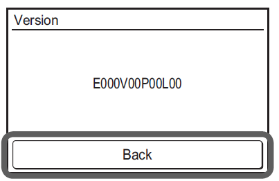
Version
- Touch the [Version] on the “Maintenance” screen. The “Version” screen is displayed. Touch [Back] to return to the “Maintenance” screen.
Test Run
Carry out a test run after completing configuration.
- Touch the [Test Run] on the “Maintenance” screen. The “Test Run” screen is dis-played.
Touch [OK] to return to the “Maintenance” screen, and start the test run. The test run will automatically end in approximately 60 min.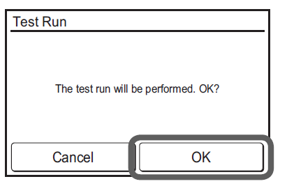
When test run is ended midway, return to the “Monitor Mode” screen and check the occupied state. When “Occupied” is displayed, press the operation button to set to “Unoccupied”. Then test run is ended. When “Unoccupied” is displayed, press the operation button once to set to “Occupied” and press it again to set to “Unoccupied”. Then test run is ended.
R.C. Address Setting
- Remote controller address can be set automatically. Addresses will be automatically set when initially starting up this unit.
- When an administrator wants to manage the remote controller address of the indoor unit, it is necessary to perform “Manual Address Setting” described below.
[Setting the remote controller address at the side of the indoor unit]
- If the address is set automatically, set the remote controller address of the indoor unit to “0”. Please do not change this setting.
- For how to confi gure the remote controller addresses for the indoor unit, refer to its installation manual.
Checking the remote controller address
- Touch the [R.C. Address Setting] on the R. “Maintenance” screen. The “R.C. Address Setting” screen is displayed.
The “Current Address” is displayed as [System-Unit]. The value for “Unit” refers to the remote controller address. Touch [Back] to return to the “Maintenance” screen.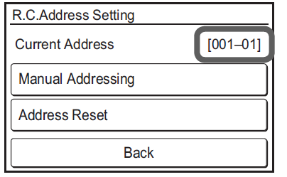
Manual Address Setting
Remote controller address can be manually set to any number.
[Setting the remote controller address at the side of the indoor unit]
- A remote controller address for the indoor unit needs to be set.
- Set the remote controller addresses for the indoor units which are connected using the same remote controller cable with a range from 1 to 9 and from A (10) to F (15), without any duplicates. (Do not use “0” for configuration.)
- For how to configure the remote controller addresses for the indoor unit, refer to its installation manual.
- Touch the [RC Address Setting] on the “Maintenance” screen. The “R.C. Address Setting” screen is displayed.
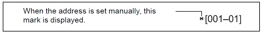
Touch the [Manual Addressing]. The “Manual Addressing” screen is displayed. - Touch to set the addresses of this unit. Touch [OK] to display the confi rmation screen, and touch [Yes] to return to the RC Address setting screen.
If you wish to carry out confi guration again, touch [Address Reset] on the “R.C. Address Setting”.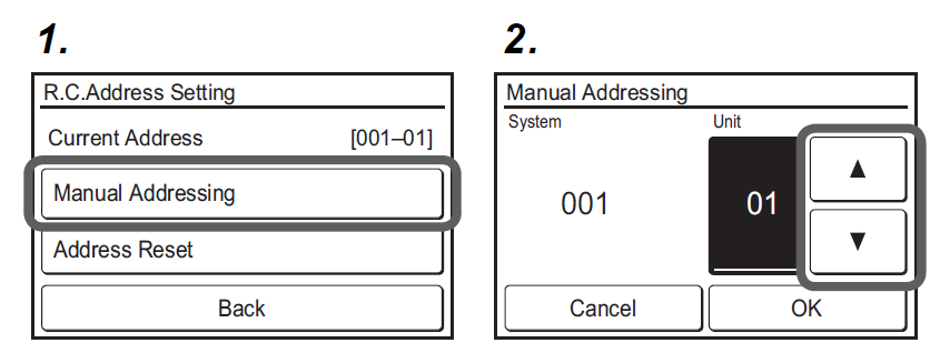
The address for this unit can be set from 1 to 32. However, do not set the same number as that for the remote controller address of an indoor unit connected using the same remote controller cable.
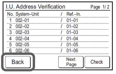
I.U. Address Verifi cation
Check the address and position of the indoor unit.
- Touch the [I.U. Address Verifi cation] on the “Maintenance” screen. The “I.U. Address Verifi cation” screen is displayed.
If there are multiple pages, you can switch between them by touching [Next Page] or [Previous Page]. Touch [Check] to display the indoor unit address checking start screen. - Touch [Yes] to display the confirmation screen.
- Select the indoor unit to be checked. If there are multiple pages, you can switch between them by touching [Next Page] or [Previ-ous Page]. The selected indoor unit will start to blow air and fl ash a LED*. (*Only when the indoor unit has the relevant functions) Touch [Back] on the confirmation screen to return to the previous screen.
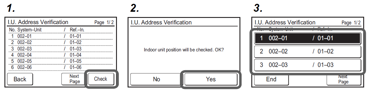
- Touch [Back] on the “IU Address Verification” Screen to return to the “Maintenance” Screen.
Function Setting
This procedure changes the function settings used to control the indoor unit according to the installation conditions. Incorrect settings can cause the indoor unit to malfunction. Perform the “Function Setting” according to the installation conditions using the remote controller.
Refer to the indoor unit installation manual for details on the function numbers and setting numbers, before the start of function setting.
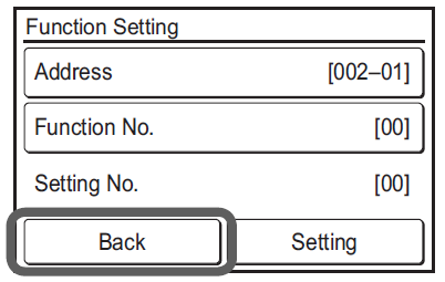
- Touch the [Function Setting] on the “Maintenance” screen. The “Function Setting” screen is displayed.
Touch the [Address] on the “Function Setting” screen. The “Address” screen is displayed. - Touchto select the address of the indoor units to be configured. (To set all indoor units at the same time, touch [All].) Touch [OK] to return to the Function Setting screen.
- Touch the [Function No.] on the “Function Setting” screen. The “Function No.” screen is displayed.

- Touchto set the function number. Touch [OK] to return to the “Function Setting” screen.
- Touch the [Setting No.] on the “Function Setting” screen. The “Set-ting No.” screen is displayed.
- Touch to set the setting number. Touch [OK] to return to the “Function Setting” screen.
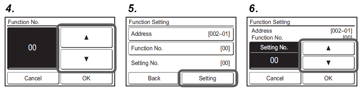
- Touch [Back] to return to the “Maintenance” screen.
Display Sensor Values
- Touch the [Display Sensor Values] on the “Maintenance” screen. “Unit Selection” screen is displayed.
Select the air conditioner which you want to monitor. If 4 or more air conditioners are registered, this screen has multiple pages. To switch the page, touch the [Next Page] or [Previous Page]. - Select the category about which you want to monitor.
- If you select [Sensor ID], input the ID of the monitoring item on the next screen.
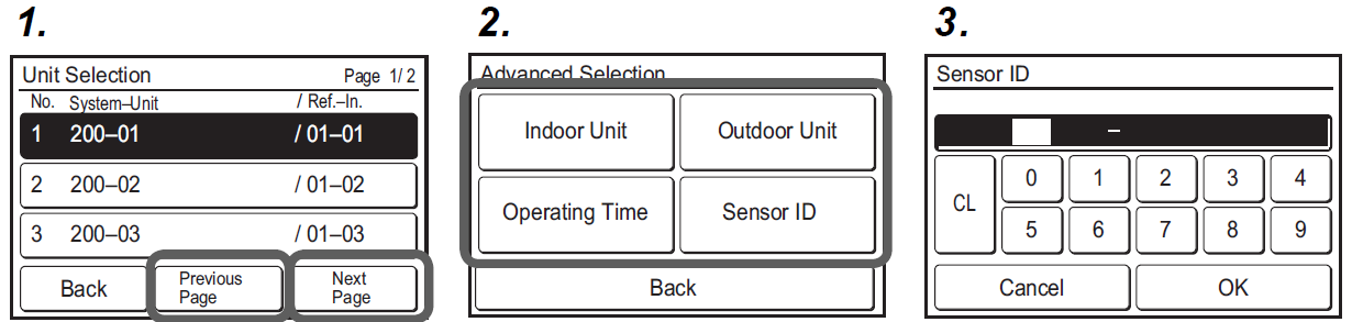
- Information on the selected category is displayed. When the screen has multiple pages, they can be switched by touching the [Next Page] or [Previous Page].
When the [End] is touched, the display returns to the “Monitor Type Selection” screen.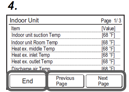
Installer Password Change
Change the Installer password.
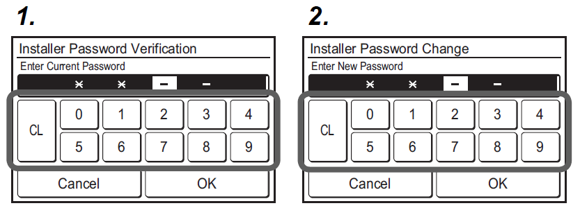
- Touch the [Installer Password Change] on the “Maintenance” screen. The “Installer Password Verifi cation” screen is displayed. Enter the current password, then touch the [OK].
The default password is “0000” (4 digits). - The “Installer Password Change” screen is displayed. Enter the new password, then touch the [OK]. It returns to the “Maintenance” screen.
Initialization
Require an Installer password.
- Touch the [Initialization] on the “Maintenance” screen. Enter the Installer password. The “Initialization” screen is displayed.
When the [OK] is touched, this unit restarts automatically after initialization. Perform each setting.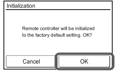
When relocating the set remote controller, initialize it.
NOTE: If you switch to a new (diff erent) remote controller when “Lead Lag Operation” is in the “Enable” state, you must hold the power button for 5 seconds or more when the “Initialization” screen is displayed. If you do not perform this operation, the “Lead Lag Setting” menu will not be displayed. When you perform this operation, “Lead Lag Operation” will be forcibly set to “Disable”.
TEST RUN
Refer to the indoor unit installation manual.
For how to carry out a test run, refer to 6. 4. Maintenance (Other Settings) 6.4.5. Test Run.
ERROR CODES
Check the error
- If an error occurs, an error icon appears on the “Monitor mode screen”.
Touch the [Status] on the “Monitor mode screen”. The “Status” screen is displayed. - Touch the [Error Information] on the “Status” screen. The “Error Information” screen is displayed. (If there are no errors, the [Error Information] will not be displayed.)
- 2-digit numbers correspond to the error code in the table below. Touch the [Next page] (or [Previous page]) to switch to other connected indoor units.
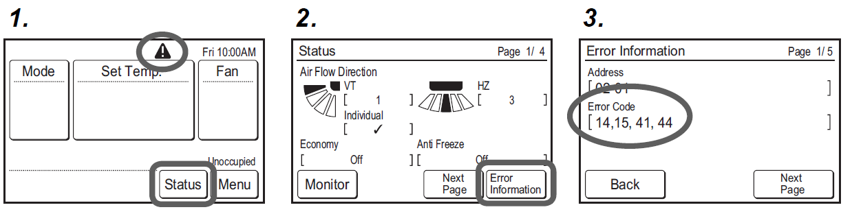
For the details of the indoor unit or outdoor unit error, refer to the error codes in each installation manual.
| Error code | Contents |
| CC.1 | Sensor error |
| C2.1 | Transmission PCB error |
| 12.1 | Wired remote controller communication error |
| 12.3 | Number excess of device in wired remote controller system |
| 12.4 | Wired remote controller system start-up error |
| 26.4 | Address duplication in wired remote controller system |
| 26.5 | Address setting error in wired remote controller system |
| 15.4 | Data acquisition error |
Reference
Download Manual:
Fujitsu UTY-RNRUZ5 Wired Remote Thermostat Installational Manual
OTHER MANUALS
Fujitsu UTY-RNRUZ5 Wired Remote Thermostat Operational Manual
Fujitsu UTY-RNRUZ5 Wired Remote Thermostat Product Specifications Guide
![]()
Fujitsu UTY-RNRUZ5 Wired Remote Thermostat Installational Manual