
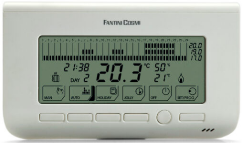
Fantini cosmi CH130ARR2 Fan-coil Room Thermostat
Introduction
Thank you for purchasing a FANTINI COSMI S.p.A. product Please read this instruction manual carefully and always keep it at hand should you need to consult it for any reason. The documentation reflects the characteristics of the product. However, for regulatory or commercial developments, customers should verify the availability of updates relating to this documentation on the FANTINI COSMI S.p.A. website: pdf.fantinicosmi.it
OPERATION
The unit CH130ARR2 is a kit consisting of a thermostat CH130AR2 and an actuator CH176D that connected with a bipolar cable, allows the remote control of two valves, the three-speed motor, or a 0 ..10V motor, of a fan coil. The thermostat reads the room temperature and controls it from the fan coil’s motor valves and speed in order to obtain the best climate comfort. Fan adjustment can be automatic or manual, depending on the settings made by the user from the function keys, which, together with the LCD screen facilitates daily operation of the system. The non-polarised bipolar cable connecting the thermostat to the module has dual function:
- thermostat power supply,
- communication bus between thermostat and actuation module.
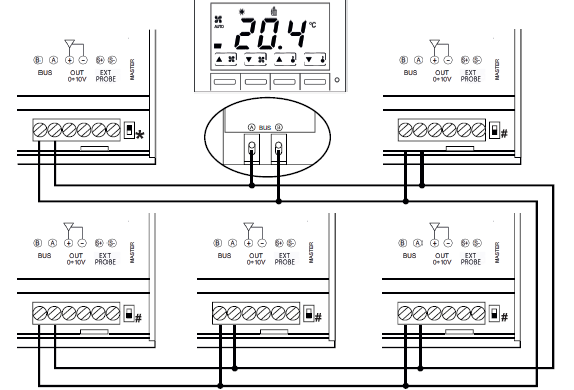
It is possible to connect a single thermostat to several actuators in order to control more fan coils simultaneously with only two cables. For this application, follow the detailed instructions in the unit installation manual CH176D
CONTENTS OF PACKAGE
- 1 thermostat
- 2 screws
- 1 user manual
- 1 actuator
DESCRIPTION OF DISPLAY KEYS
CONTROLS
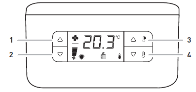
- Increases the fan speed or sets automatic ventilation
- Reduces the ventilation speed or sets OFF mode (thermostat off).
- Increases the current temperature set point
- Decreases the current temperature set point
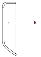
- Thermostat reset without loss of settings
ADVANCED CONTROLS
Simultaneously pressing the two keys enables the following settings:
- 1 and 2 Comfort/Economy mode change
- 3 and 4 Summer/Winter mode change (pressing > 3 sec)
WARNINGS KEY
- Measured or set temperature
- Comfort mode
- Economy mode
- Summer mode
- Winter mode
- Fan speed indicator (MIN-MED-MAX)
- Automatic fan mode
- Fan-coil cooling enabled
- Fan-coil heating enabled
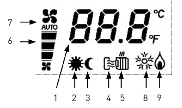
Note: in 4-pipe plants, when both symbols 4 and 5 light up it indicates AUTOMATIC mode. With the active minimum sensor function, the symbol 8 or the flashing symbol 9 indicates that the supply water temperature is outside the set limits. In this case, ventilation is interrupted.
TECHNICAL FEATURES
- Power supply: via remote actuator CH176D
- Exit: Proprietary BUS
- Auxiliary input: for potential-free contact
- Probe input: NTC 10KOhm (Fantini EC15-EC18-EC19-EC20)
- Electrical connections: screw clamps
- Protection rating: IP20
- Degree of pollution: 2
- Settings memorization: non-volatile memory
- Software: Class A
- Temperature adjustment field: 2°C – 40°C
- Maximum temperature: T45
- User interface: LCD display and 4 keys
- Dimensions (L x H x D): 135 x 83 x 21 mm
- Reference thermal gradient: 4 K/h
- Complies with Directives: Directive 2014/35/EU or Directive 2014/30/EU
- Complies with Standards: EN60730-1 EN60730-2-9
- ErP classification: ErP Class I; 1% or [Reg. EU 811/2013 – 813/2013]
INSTALLATION
ATTENTION!
- Installation must be carried out by qualified personnel, in compliance with the requirements concerning installation of electrical devices.
- Make sure that the power network is disconnected before making any connections or working on the device.
The thermostat CH130AR2 is supplied with a base suitable for assembly both wall-mounted and recessed in rectangular 3-place box (503) or round.
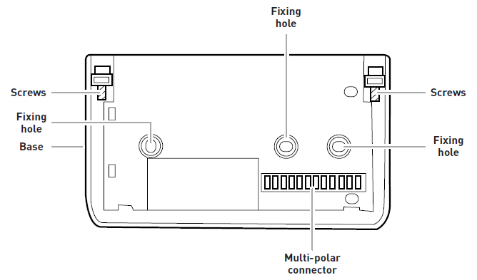
- Remove the top cover of the thermostat.
- Divide the base and front of the thermostat by removing the screws with a specific tool and extracting the front part.
- Fix the base to the required surface by means of the specific fixing holes; and make sure that the base is well secured, without deformations and that the multi-polar connector is at the bottom right corner.
- For proper operation, the base must be approximately 1.5 metres above the floor, away from heat sources (direct sunlight, etc.) and from doors and windows.
- Insert the thermostat on the base and screw it, making sure that the multi-polar connector is inserted properly.
- Refit the top cover.
ELECTRICAL CONNECTION
For further information regarding connection of the thermostat-actuator-fan coil system, refer to the connection diagrams in the CH176D unit installation manual. Electrical connections must be carried out as shown in the connection diagram. Please note that connection of the external probe (EXP1) and input for remote control (SEL1), are subject to certain configuration parameter settings.
Connection of the actuator
Connect the power wires coming from the actuator CH172D to terminals A and B, as shown in the figure. Flexible conductors with a max cross-section of 2.5 mm2 can fit in the terminals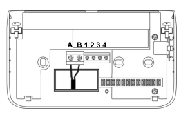
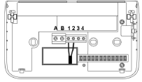
Connection of auxiliary input
Connect the two auxiliary input wires to the screw terminals 1 and 2, as shown in the figure.
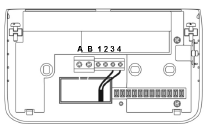
Connection of the external probe
Connect the two wires of the external probe to the screw terminals 3 and 4, as shown in the figure.
DIRECTIONS
START-UP
To start the thermostat after installation, follow the procedure below:
- Configure the functional parameters (by the installer).
- Set the operating mode (Summer or Winter).
- Set the operating mode (Comfort or Economy).
- Set the fan speed ((MIN-MED-MAX or Automatic).
SUMMER/WINTER MODE SELECTION
The current operating mode is indicated by the relative symbol. To change current operating mode settings, simultaneously press keys 1 and 2 (pressing > 3 sec).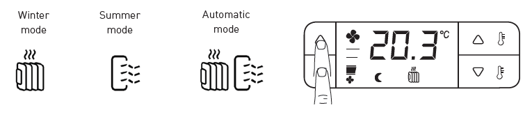
Note: the operating mode cannot be changed if the thermostat is enabled to manage change-over (locally or remotely) or if the 4-pipe system is enabled in AUTOMATIC mode.
OPERATING MODES
- The thermostat has three different operating modes: Comfort, Economy, OFF.
- The current setting is displayed with the relative symbols.
- The room temperature is displayed during normal operation. To view the value of the temperature adjustment setting in the current operating mode, press key 3 or 4.

COMFORT MODE
- In this mode, the thermostat controls the temperature in order to keep the set Comfort temperature constant.
- To change from Economy to Comfort, simultaneously press keys 3 and 4.
- To check the currently set Comfort temperature, press key 3 or 4.
- To change the set Comfort temperature value, repeatedly press key 3 (to increase it) or key 4 (to decrease it). The temperature is changed in steps of 0.1°C.

ECONOMY MODE
- In this mode, the thermostat controls the temperature in order to keep the set Economy temperature constant.
- To change from Comfort to Economy, simultaneously press keys 3 and 4.
- To check the currently set Economy temperature, press key 3 or 4.
- To change the set Comfort temperature value, repeatedly press key 3 (to increase it) or key 4 (to decrease it). The temperature is changed in steps of 0.1°C.

OFF
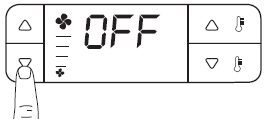
In this mode, the thermostat stops any adjustment. If the thermostat is in winter mode, only antifreeze protection is active. To check the currently set antifreeze temperature, press key 3 or 4. To change the set Antifreeze temperature value, repeatedly press key 3 (to increase it) or key 4 (to decrease it). The temperature is changed in steps of 0.1°C. To switch to OFF mode, repeatedly press key 2 to decrease the fan speed until the wording OFF appear on the screen
FAN SPEED SETTING
There are three different fan speeds: minimum, medium, and maximum. The speed can be set manually by selecting one of the three speeds, or automatic. In AUTO, the thermostat will use the most suitable fan speed to reach and maintain the requested room temperature.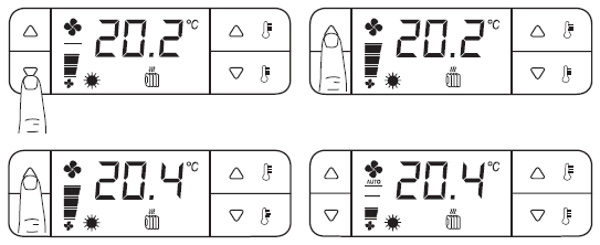
KEY LOCK
To enable the key lock function, useful in preventing the thermostat from being used by unauthorised persons, follow the steps below:
- Enter the thermostat configuration menu
- In parameter P01 enter a password other than 000
- Exit the thermostat configuration menu
- The key lock is active.
- To disable the key lock function, perform the operations described above again and, after entering the current password, set parameter P01 to 000.
TEMPORARY KEY UNLOCK
- When one of the disabled keys is pressed, in accordance with parameter P20, the display will show “Loc” and, below, 000 will flash, inviting you to enter the unlock password.
- Confirm by pressing key 3 or 4.
- The keys will be locked automatically one minute after the last time any of them were pressed.
FAULTS
The presence of one or more faults is indicated on the display by the following error codes:
- E01 External temperature probe failure
- E02 Temperature probe failure on remote actuator
- E03 Remote actuator CH176D does not respond to messages
- E04 Internal temperature probe failure
MAINTENANCE
It is recommended to use a soft cotton cloth without any detergent to clean the thermostat.
THERMOSTAT CONFIGURATION
ATTENTION!
Thermostat parameters configuration must only be carried out by qualified technical personnel. Thermostat operation in relation to a specific design is subject to correct setting of certain operation configuration parameters, which can be consulted and/or edited by accessing a technical menu, as described below:
- Press RESET and key 4;
- Release RESET whilst holding key 1 for minimum 3 seconds;
- Release key 1.
P01 is displayed on the screen, which refers to the first alphanumeric identification index of the parameters list.
- The configuration parameters are displayed with an alphanumeric index P… (P01- P51); press keys 1 and 2 to scroll through the entire list of parameters.
- To display the current setting or edit an individual parameter, press key 3. Then press keys 1 and 2 to select the new setting and confirm by pressing 3.
- Once the parameter settings have been completed, press 1 until the wording END appears and press 3 to confirm. The thermostat will save the new parameters in the non-volatile memory and go back to normal operation.
Note: the thermostat forwards the various controls (valves control, fan speed control) to the CH176D actuation unit every minute.
USER-EDITABLE PARAMETERS
| PARAMETER | DESCRIPTION | DEFAULT | FIELD |
| P01 | Password | 000 | 000: password disabled
386: universal password |
| P02 | Unit of measure | CEL | CEL: Celsius
FAH: Fahrenheit |
| P03 | Auxiliary input status display (AUX IN) | cL: closed
oP: open |
|
| P04 | Temperature display on remote actuator input | -50°C … 50°C
cL: closed oP: open |
|
| P05 | Temperature display on external sensor input | -50°C … 50°C
cL: closed oP: open |
|
| End | Exit the user parameters menu + save parameters.
If keys 1-2-4 are pressed simultaneously for three seconds, you access the hidden menu for changing the system installation parameters (P06…P51). These parameters should only be configured by qualified technical personnel. |
End |
SYSTEM INSTALLATION PARAMETERS (HIDDEN MENU)
| PARAMETER | DESCRIPTION | DEFAULT | FIELD |
| P06 | Plant type (PLANT) | 2P | 2P: 2 pipes
4P: 4 pipes |
| P07 | Hot water/electrical resistance valve selection | 1 | 1: hot water valve
2: electrical resistance |
| P08 | Ventilation modes | 1 | 1: continuous
2: continuous-stop winter mode 3: continuous-stop summer mode 4: subordinated to valve status 5: subordinated-stop in winter mode 6: subordinated-stop in summer mode |
| P9 | Adjustment modes | 1 | 1: Manual Winter/Summer mode
2: Automatic Winter/Summer mode |
| P10 | Anti-stratification | 1 | 1: not active
2: summer only 3: winter only |
| P11* | Temperature sensor on remote actuator sensor input
Reading frequency : Once a minute |
1 | 1: not connected
2: winter only minimum sensor 3: winter/summer minimum sensor 4: automatic change-over 5: return ( only if P13 is other than 6 ) |
| P12 | Temperature sensor on external sensor input Reading frequency : Once a minute
Options 7-8-9 are only visible if CH172D was selected as remote actuator ( P51 ) |
1 | 1: not connected
2: ON/OFF 3: manual change-over 4: comfort/economy 5: reduction (-3.0°C winter +3.0°C summer) 6: return ( only if P12 is other than 5 ) 7: winter only minimum sensor 8: winter/summer minimum sensor 9: automatic change-over |
| P13 | Auxiliary input
Reading frequency : Once every 10 seconds |
1 | 1: not connected
2: ON/OFF 3: manual change-over 4: comfort/economy 5: reduction (-3.0°C winter +3.0°C summer) |
| P14 | P13 – P14 input polarity | 1 | n.o. normally open
n.c. normally closed 1: P12 (n.o.) P13 (n.o.) 2: P12 (n.o.) P13 (n.c.) 3: P12 (n.c.) P13 (n.o.) 4: P12 (n.c.) P13 (n.c.) |
| P15 | Room temperature correction | 0.0 °C | -4.0°C … 4.0°C (0.1°C step) |
| P16 | Temperature correction on external sensor | 0.0 °C | -4.0°C … 4.0°C (0.1°C step) |
| P17 | Temperature correction on remote sensor | 0.0 °C | -4.0°C … 4.0°C (0.1°C step) |
| PARAMETER | DESCRIPTION | DEFAULT | FIELD |
| P18 | Display mode | 1 | 1: Troom view
2 = set point view |
| P19 | OFF display mode | 1 | 1: ‘OFF’ view
2: view from P18 |
| P20 | Key lock mode | 1 | 1 All keys locked
2: Setpoint + W/S + E/C key lock 3: W/S + E/C key lock |
| P21 | Regulation differential in winter mode | Std | Std / 0.3°C … 5.0°C (step 0.1°C) |
| P22 | Regulation differential in summer mode | Std | Std / 0.3°C … 5.0°C (step 0.1°C) |
| P23 | Summer set point upper limit comfort | 30.0 °C | 2.0°C … 30.0°C (0.1°C step) |
| P24 | Summer set point lower limit comfort | 2.0 °C | 2.0°C … 30.0°C (0.1°C step) |
| P25 | Summer set point upper limit economy | 30.0 °C | 2.0°C … 30.0°C (0.1°C step) |
| P26 | Summer set point lower limit economy | 2.0 °C | 2.0°C … 30.0°C (0.1°C step) |
| P27 | Winter set point upper limit comfort | 30.0 °C | 2.0°C … 30.0°C (0.1°C step) |
| P28 | Winter set point lower limit comfort | 2.0 °C | 2.0°C … 30.0°C (0.1°C step) |
| P29 | Winter set point upper limit economy | 30.0 °C | 2.0°C … 30.0°C (0.1°C step) |
| P30 | Winter set point lower limit economy | 2.0 °C | 2.0°C … 30.0°C (0.1°C step) |
| P31 | Upper limit set-point automatic regulation | 30.0 °C | 2.0°C … 30.0°C (0.1°C step) |
| P32 | Lower limit set-point automatic regulation | 2.0 °C | 2.0°C … 30.0°C (0.1°C step) |
| P33 | Minimum sensor threshold in winter mode | 34.0 °C | 28.0°C … 42.0°C (step 0.1°C) |
| P34 | Minimum sensor threshold in summer mode | 22.0 °C | 10.0°C … 25.0°C (step 0.1°C) |
| P35 | Minimum sensor tripping differential | 4.0 °C | 2.0°C … 6.0°C (0.1°C step) |
| P36 | Lower change-over temp. threshold | 22.0 °C | 15.0°C … 24.0°C (step 1.0°C) |
| P37 | Upper change-over temp. threshold | 32.0 °C | 26.0°C … 35.0°C (step 1.0°C) |
| P38 | Dead zone range (automatic regulation) | 2.0 °C | -1.0°C … 6.0°C (1.0°C step) |
| P39* | Minimum manual fan speed (0..10V) | 1.0V | 1.0V … 6.0V (step 0.1V) |
| P40* | Medium manual fan speed (0..10V) | 5.0V | 3.0V … 8.0V (step 0.1V) |
| P41* | Maximum manual fan speed (0..10V) | 10.0V | 6.0V … 10.0V (step 0.1V) |
| P42 | Ventilation speed change-over hysteresis (IrL) | 0.5 °C | 0.5°C … 2.0°C (0.1°C step) |
| P43* | Minimum winter automatic fan speed (0..10V) | 1.0V | 1.0V … 6.0V (step 0.1V) |
| P44* | Maximum winter automatic fan speed (0..10V) | 10.0V | 5.0V … 10.0V (step 0.1V) |
| P45* | Minimum summer automatic fan speed (0..10V) | 1.0V | 1.0V … 6.0V (step 0.1V) |
| P46* | Maximum summer automatic fan speed
(0..10V) |
10.0V | 5.0V … 10.0V (step 0.1V) |
| P47 | Proportional band in winter automatic mode | 3.5 °C | 2.0°C … 6.0°C (0.1°C step) |
| P48 | Proportional band in summer automatic mode | 3.5 °C | 2.0°C … 6.0°C (0.1°C step) |
| P49* | Enable ventilation relay | YES | YES: relays enabled + 0..10V output
no: relays disabled (only 0..10V output) |
| P50 | Remote actuator selection | 176 | 176: CH176D
172: CH172D |
| P51 | Restoring factory settings (default) | no | no
YES |
P06 Plant type (plant)
- 2P 2-PIPE SYSTEM: the thermostat only manages valve V1 (on/off type) regardless of heating or cooling operation.
- 4P 4-PIPE SYSTEM: the thermostat manage valve V1 (on/off type) for heating and valve V2 (ONE/OFF type) for cooling.
P07 Hot water valve
- HOT VALVE: actuator output V1 controls the water supply valve in heating.
- ELECTRICAL RESISTANCE: actuator output V1 controls an electrical resistance for heating. In this case, when the resistance is switched off, the fan still remains active (two minutes of post-ventilation) to enable the resistance to cool down.
P08 Ventilation modes
- CONTINUOUS: once the set point is reached, the fan still remains active at the manually set speed or at MIN speed if automatic ventilation is set.
- CONTINUOUS-STOP IN WINTER MODE: as in 1 except in heating where ventilation is switched off.
- CONTINUOUS-STOP IN SUMMER MODE: as in 1 except in cooling where ventilation is switched off.
- AUXILIARY: the fan is only enabled if the valve is enabled (heating or cooling in progress).
- SUBORDINATED-STOP IN WINTER MODE: as in 4 except in heating where ventilation is switched off.
- SUBORDINATED-STOP IN SUMMER MODE: as in 4 except in cooling where ventilation is switched off.
P09 Adjustment modes
- SUMMER/WINTER: the thermostat carries out temperature control according to the current mode (Summer/Winter).
- AUTOMATIC: the thermostat carries out temperature control by heating or cooling in order to obtain the best climate comfort (4-pipe systems only)
Note: when selecting option 2, the adjustment involves parameter P38; By selecting option 2 SUMMER/WINTER mode cannot be changed manually.
P10 Anti-stratification operation
This setting is only effective if P11=5 or P12 = 6 (adjustment with return sensor)
- NOT ACTIVE: the function is not managed.
- SUMMER ONLY: the function is only managed if the thermostat is in summer mode.
- WINTER ONLY: the function is only managed if the thermostat is in winter mode.
Note: if ventilation is not active for 15 straight minutes, the anti-stratification function switches on for two minutes ventilation at MEDIUM speed regardless of minimum sensor consent.
P11 Temperature sensor on remote actuator sensor input
- NOT CONNECTED: the input is not used.
- MINIMUM SENSOR WINTER ONLY: connecting a temperature probe to the supply pipe, the thermostat will not start the fan until the temperature of the water has reached the value set in item P33.
- SUMMER/WINTER MINIMUM SENSOR: connecting a temperature probe to the supply pipe, the thermostat will not start the fan until the temperature of the water has reached the value set in item P33 (winter mode) or P34 (summer mode).
- CHANGE-OVER SENSOR: connecting a temperature probe to the supply pipe, the thermostat automatically manages the Winter/Summer change-over with the temperatures programmed in items P36 and P37.
- AIR RETURN SENSOR: connecting a temperature probe in the air return point (usually under the fan coil), the thermostat manages temperature control with the temperature read by this probe.
Note: by selecting option 4 SUMMER/WINTER mode cannot be changed manually.
P12 Temperature sensor on external temperature sensor input
- NOT CONNECTED: the input is not used.
- ON/OFF: by connecting a normally open or normally closed contact, according to what is selected in item P14, the thermostat goes into off mode or on mode.
- Manual change-over: by connecting a normally open or normally closed contact, according to what is selected in item P14, the thermostat goes into winter mode or summer mode.
- Comfort/economy: by connecting a normally open or normally closed contact, according to what is selected in item P14, the thermostat goes into comfort mode or economy mode.
- REDUCTION: connecting a normally open or normally closed contact, according to what is selected in item P14, there is a reduction of 3.0°C in the setpoint temperature value in winter mode, or an increase of 3.0°C in the setpoint temperature value in summer mode.
- AIR RETURN SENSOR: connecting a temperature probe in the air return point (usually under the fan coil), the thermostat manages temperature control with the temperature read by this probe.
- MINIMUM SENSOR WINTER ONLY: connecting a temperature probe to the supply pipe, the thermostat will not start the fan until the temperature of the water has reached the value set in item P33.
- SUMMER/WINTER MINIMUM SENSOR: connecting a temperature probe to the supply pipe, the thermostat will not start the fan until the temperature of the water has reached the value set in item P33 (winter mode) or P34 (summer mode).
- CHANGE-OVER SENSOR: connecting a temperature probe to the supply pipe, the thermostat automatically manages the Winter/Summer change-over with the temperatures programmed in items P36 and P37.
P13 Auxiliary input
- NOT CONNECTED: the input is not used.
- ON/OFF: by connecting a normally open or normally closed contact, according to what is selected in item P14, the thermostat goes into off mode or on mode.
- Manual change-over: by connecting a normally open or normally closed contact, according to what is selected in item P14, the thermostat goes into winter mode or summer mode.
- Comfort/economy: by connecting a normally open or normally closed contact, according to what is selected in item P14, the thermostat goes into comfort mode or economy mode.
- REDUCTION: connecting a normally open or normally closed contact, according to what is selected in item P14, there is a reduction of 3.0°C in the setpoint temperature value in winter mode, or an increase of 3.0°C in the setpoint temperature value in summer mode.
P15 Room temperature correction
P16 Temperature correction on external sensor
P17 Temperature correction on remote sensor
These parameters are used to correct the room temperature value read, since in certain installations, the room temperature read may be unsatisfactory due to the position of the probe (internal or return).
P18 Display mode
- Troom: the display usually shows the room temperature.
- Set-point: the display always shows the current temperature set point value.
P19 OFF display mode
- The display shows ‘OFF’.
- The display shows the room temperature or set-point according to what is selected under P19.
P20 Key lock mode
With active password, select the number and type of locked keys.
- All keys locked
- Key lock applied to set-point editing, changing from summer to winter mode and vice versa, and changing from comfort set-point to economy set-point and vice versa.
- Key lock applied to changing from summer to winter mode and vice versa, and changing from comfort set-point to economy set-point and vice versa.
P21-P22 Adjustment differential
- The differential value that can be set is between 0.3°C and 5.0°C, or standard Std (default = Std).
P33 Minimum sensor threshold triggered (winter mode)
- This setting is only effective if P11 = 2 or P11 = 3 or P12= 7 or P12 = 8
- When the supply temperature falls below the set value, the thermostat stops ventilation.
P34 Minimum sensor threshold triggered (summer mode)
- This setting is only effective if P11 = 2 or P11 = 3 or P12 = 7 or P12 = 8
- When the supply temperature rises above the set value, the thermostat stops ventilation.
P36 Lower change-over threshold
- This setting is only effective if P11 = 4 or P12= 9
- When the supply temperature drops below the set value, the thermostat automatically switches from heating to cooling.
P37 Upper change-over threshold
- This setting is only effective if P11 = 4 or P12 = 9
- When the supply temperature rises above the set value, the thermostat automatically switches from cooling to heating.
P38 Dead zone interval
- When the thermostat operates in AUTOMATIC with subordinated ventilation in the dead zone, the fan is off; with continuous ventilation, minimum speed remains enabled.
P50 Remote actuator selection
- Selection of the remote actuator model that CH133AR2 will be connected to:
- 176: CH176D (equipped with remote temperature sensor and 0..10V output)
- 172: CH172D (relay only)
DIN RAIL CH176D ACTUATOR
OPERATION
The CH130AR2 unit is an actuation model which, connected to a thermostat for fan coil CH133AR2 – CH133RR – CH130AR2 – CH130ARR – CH130RR via a bipolar cable, allows to remotely control the two valves, the three-speed motor or a 0 .. 10V, motor, and accept a temperature sensor connected to the appropriate input.
The bipolar cable connecting the module to the thermostat, has a dual function:
- powering the fan coil thermostat,
- communication bus between thermostat and actuation module.
The CH130AR2C unit is compatible with the CH172D actuator via external set-up. It is possible to connect a single thermostat to several actuators, so as to control more than one fan coil simultaneously with only two cables; for this application, carefully follow the detailed instructions in the document.
TECHNICAL FEATURES
- Power supply and absorbed power 230Vac 50Hz – 2VA
- BUS A/B input Power supply + thermostat data (default setting: SLAVE)
- Relay output features 5(3)A 250V~
- Voltage-free switching contacts with mains voltage 2 valve outputs (N-V1 and N-V2)
- Mains voltage switching contacts 3 motor contact outputs (M1, M2 and M3) 0 … 10V output 20 mA – 470Ω
- Probe input NTC 10 KΩ (Fantini EC15-EC18-EC19-EC20)
- Protection rating IP00
- Software class A
- Maximum temperature T45
- Degree of pollution 2
- Complies with Standards EN60730-1 and second parts
- Micro-disconnection 1B
- Impulse voltage 4000V
- Assembly type and dimensions 6-module DIN Rail
The device is designed for installation on DIN rail, but its small size facilitate the installation inside the fan coil also.
ATTENTION!
The end parts (live) of the CH176D must be installed in a container or fan coil inaccessible by the user. Installation must be carried out by qualified personnel, in compliance with the requirements concerning installation of electrical devices. Make sure that the power network is disconnected before making any connections or working on the device.
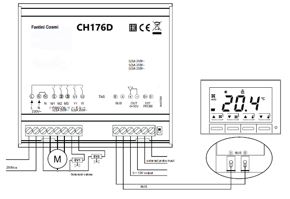
- The following figure shows the circuit diagram of the connections.
- The distance between the actuator module and thermostat must not exceed 100 metres.
- In air conditioning systems with four pipes, valve 1 (terminals N and V1) controls the heating circuit while valve 2 (terminals N and V2) controls the cooling circuit.
- The temperature sensor (NTC 10KΩ) must be connected to the PROBE input. The 0 … 10V motor must be connected to the specific 0-10V OUT output, respecting its polarities.
CONNECTING SEVERAL MODULES TO ONE THERMOSTAT
A CH133AR2 – CH133RR – CH130AR2 – CH130ARR – CH130RR thermostat can control up to five fan-coils simultaneously, using only two wires to connect to the various actuation modules. In this case, only one of the two CH176D modules must have the “BUS selector” in “MASTER” position, while all others must be left in “SLAVE” mode (default setting). The temperature probe connected to the actuation module set up as “MASTER” is the one read by the thermostat. The connection between the various devices must be made as per the diagram in the following figure
OPERATING MODE SELECTION
If thermostats CH133RR – CH130RR – CH130ARR are connected to the actuation module, it must be configured in CH172D mode. The selection is made by switching on the actuation module by means of the configuration of the probe input according to the following diagram:
- CH176D: probe input free or connected to a temperature probe
- CH172D: temperature probe input permanently short-circuited by means of a conductor cable
LUMINOUS STATUS INDICATOR
- The CH176D unit is equipped with a status indicator made via a two-coloured LED diode.
- Flashing red: the actuation module is configured as Master and is receiving a command from the thermostat.
- Flashing green: the actuation module is configured as Slave and is receiving a command from the thermostat.
- Flashing red and green alternately: protection. After twenty minutes during which the actuation module does not receive commands from the thermostat, the relays are deactivated and the 0 … 10V output is brought to 0V.
- Upon reception of a command, the actuation module resumes normal operation
COMMISSIONING AND OPERATIONAL CHECK
Commissioning and testing procedure:
- make sure that the actuator is properly connected to the thermostat;
- set the “BUS selector” to ON (MASTER);
- set up the actuation module as CH176D or CH172D (according to the thermostat connected to it);
- supply 230Vac power to the actuator;
- check that the thermostat is turned on;
- by consulting the manual of the thermostat, set it in the different operating modes (winter and summer) with consistent set-points and gradually select the various ventilation speeds (1, 2 and 3), check switching of the various relay and the subsequent actuations of the V1/V2 valves and the fan coil motor
DISPOSAL
The symbol of the crossed-out wheeled bin indicates that the products must be collected and disposed of separately from household waste. The batteries and integrated accumulators may be disposed of together with the product. They will be separated at the recycling facilities. A black bar indicates that the product was placed on the market after 13 August 2005. Participating in the separate collection of products and batteries contributes to the correct disposal of these materials and therefore avoids possible negative consequences for the environment and human health. For more detailed information on the collection and recycling programmes available in your country, contact the local authorities or the sales point where you purchased the product.
GENERAL WARRANTY CONDITIONS
The conventional warranty lasts 24 months, starting from the date the equipment is installed. The warranty covers all parts of the equipment, with the exception of those subjected to normal wear through use.
FANTINI COSMI S.p.A.
- Via dell’Osio, 6 20090 Caleppio di Settala, Milan – ITALY
- Tel. +39 02 956821
- Fax +39 02 95307006
- [email protected]
- www.fantinicosmi.it
REFERENCE:
DOWNLOAD MANUALS:
Fantini cosmi CH130ARR2 Fan-coil Room Thermostat Instruction Manual
OTHER MANUALS:
Fantini cosmi CH130ARR2 Fan-coil Room Thermostat Product Data Sheet
Fantini cosmi CH130ARR2 Fan-coil Room Thermostat Instruction Manual