ESBE TPD214 WIRELESS DIGITAL THERMOSTAT
WIRELESS DIGITAL THERMOSTAT
- Operating frequency 868.150 MHz
- Wide back-lit display
- Heating/Cooling selection can be managed by the thermostat or on the receiver
- User enabling/disabling/limit to regulate the Set-point temperatures
- Possibility of controlling a second stage
- Internal sensor and input for remote sensor
- Indication of discharged battery
OVERVIEW
This device is a radio-controlled thermostat, endowed with a display, able to control the room temperature by which you can choose among different regulation settings and related set-point temperatures: Comfort, Economy, Off/Antifrost, etc. The thermostat is set by factory default to work in Comfort, Economy and Antifrost modes; by changing the configuration it is possible to adapt it to the different installation settings, and moreover, final user modifications can be limited, in order to maximize comfort in the environment and energy saving. The thermostat can be used in both heating and cooling systems. In heating mode it is able to drive a second stage in addition to the main one, becoming an efficient solution in rooms with two heating systems. The thermostat has a wide blue back-lit display and it is suitable for floor heating systems where it gives the possibility to install an external temperature probe on the floor, thus, enabling its temperature control.
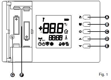
DESCRIPTION OF CONTROLS
KEY:
- A Mode Key: cycle among comfort, economy and other preset modes.
- B Menu Key: display the set-point temperature and the temperature of the external probe (when used and adequately configured).
- C On/Off Key: switches the thermostat on/off.
- D Increase key: Modifies the set-point temperatures and the configuration parameters (by increasing value).
- E Decrease key: Modifies the set-point temperatures and the configuration parameters (by decreasing value).
- F Battery compartment
- G Screw housing for fixing the thermostat body to the wall plate.
DISPLAY INDICATIONS
Below are listed the symbols that can appear on the display and their meaning: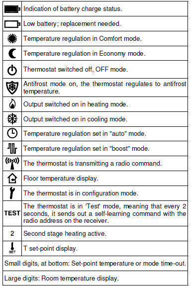
INSTALLATION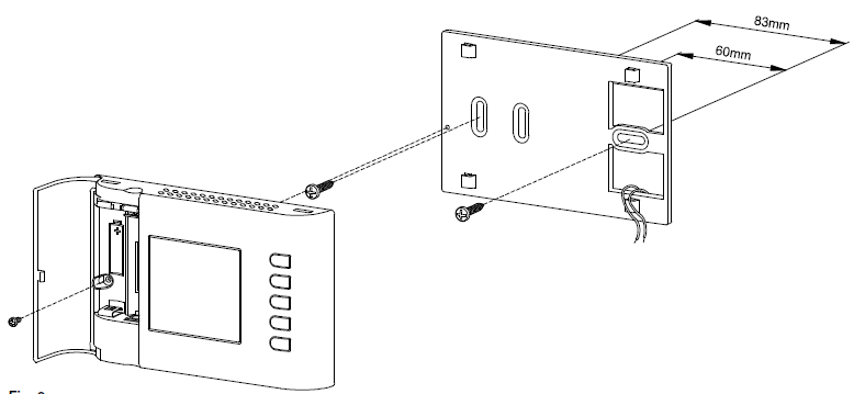
WARNING
- Ensure the transmitted radio signals are correctly received by the receiving unit before installing the thermostat.
- Install the thermostat at about 1.5 m above the floor, away from heat sources, draught and particularly cold walls (heat bridges), for room temperature to be measured correctly. These notes must be applied to position the remote sensor when this is used to acquire the room temperature.
- A remote sensor must be connected using wires having at least 1.5 mm² section and no longer than 15 metres. Do not use the same conduits for sensor signal and mains voltage.
- The installation and electrical connection of the thermostat must be carried out by qualified personnel and in compliance with current regulations.
Follow the steps below to install the thermostat:
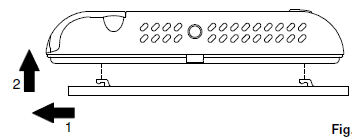
- Release the plate attached to the thermostat base by pushing it to the left, this way releasing the teeth indicated
- Correctly insert the batteries (respecting polarity) in the battery compartment ( of Fig. 1), do not use low charged batteries, use alkaline ones.
 Find the most suitable spot for the installation (see the “RADIO SYSTEM CONFIGURATION” paragraph) and fix the plate to the wall using the two seats for screws having 60 mm or 85 mm interaxial.
- Insert the wires through the rectangular opening in the wall plate following the connection diagram of to electrically connect the possible remote probe. If necessary remove jumper JP1 but before doing that read the “INSTALLER CONFIGURATION” paragraph.
- Connect the thermostat base to the wall plate by making the base holes coincide with the wall plate teeth and subsequently force the base to the right side, until the plate’s plastic tooth clicks.
- Temporarily remove the batteries and fix the thermostat body to the wall plate using the supplied screw located inside the battery compartment; re-insert the batteries with the correct polarity
- Configure the thermostat: see “INSTALLER CONFIGURATION” paragraph.
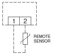
Table 1: Installer configuration Summary of the configuration parameters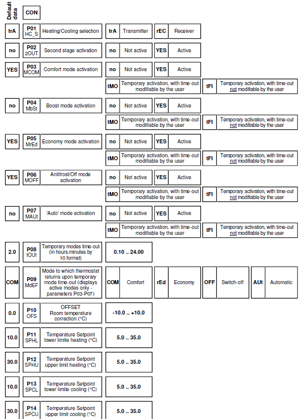
ANTIFROST TEMPERATURE
The antifrost temperature is set by factory default at 6°C and the thermostat is configured so the antifrost temperature cannot be modified by the user. If there is the need to modify it, set parameter P18 on ‘YES’; therefore, the antifrost temperature can be modified with thermostat off, using the keys ‘3’ or ‘4’.
TEMPERATURE REGULATION
The thermostat can drive the output on receiver, in ON/OFF or PWM mode. The valve’s drive in PWM mode allows proportional regulation and, therefore, to regulate the room temperature with maximum comfort and energy saving. However, different rooms require different settings to obtain a fine control.
The parameters responsible for setting quality are:
- P25 Proportional band
- P26 Integration time
The proportional band in °C is the difference between set-point and room temperature that ensures the valve is fully opened. The narrower the proportional band, the more reactive is the system upon varying of the room temperature. An excessively narrow proportional band setting can generate room temperature oscillations or system instability. An excessively large setting may lead to not reaching the set temperature on set-point in the room. No additional action is had when the integration time is set at zero and the setting is of P (Proportional) type. Regulation will be of P + I (Proportional + Integral) type by setting an integration time different from zero. The shorter the integral time the longer is the integral action, vice-versa, a long integral time generates a mild integral action. A mild or missing integral action may prevent the set temperature on set-point from being reached in the room. An excessively strong integral action may cause the room temperature to oscillate. These parameters may require modifying, depending on the room being worked on in order to obtain the best setting.
SAMPLING TIME
The thermostat detects room temperature and transmits data every 3 minutes to the receiver, in order to optimize the batteries’ duration. Therefore, it is normal for the displayed temperature not to be immediately updated and that 3 minutes must wait to see the output switch on or off; alternatively, press key ‘ ![]() ‘ to force an update.
‘ to force an update.
DISPLAY BACK-LIGHTING
Switch-on of the display Switch-off is automatic after 20 seconds from last button pressure.
BATTERIES INSERTION/REPLACEMENT
The display permanently shows the batteries charge state by means of symbol ‘ ![]() ‘. Batteries are charged to maximum if all three level indicators inside the symbol are on. On the contrary, the batteries are discharged and must be replaced when the symbol appears completely empty ‘
‘. Batteries are charged to maximum if all three level indicators inside the symbol are on. On the contrary, the batteries are discharged and must be replaced when the symbol appears completely empty ‘![]() ‘. If the batteries are excessively low, the symbol ‘
‘. If the batteries are excessively low, the symbol ‘![]() ‘ flashes, to allow radio transmission.
‘ flashes, to allow radio transmission.
Proceed as follows to replace batteries:
- Open the door accessing the battery compartment
- Remove the batteries; if needed use a tool to extract them.
- Insert the new batteries respecting the polarity; use only 1.5V alkaline AA type batteries.
COMPATIBILITY WITH NEW WAVE RADIO SYSTEM
The thermostat works with the New Wave radio receivers with the following limits on the firmware versions (FW):
- DAPF84 (active antenna): all
- DAPF84 (repeater): from FW. 021023A1 and subs.
- DLP841M (8 channel module) from FW. 020842A1 and subs.
- DLP841M001 (8 channel module): all
- DLP8412 (8 channel module): all
- DLP241M (2 channel module): from FW. 020843A1 and subs.
- DLP241M001 (2 channel module): all
- DRPF84M01 (one channel receiver): from FW. 021057A1 and subs.
- DRPF84M011 (one channel receiver): all
- Subsequent firmware versions are identified with a higher number (excluding final A1).
TECHNICAL FEATURES
- Power supply: 2 x 1.5V= alkaline AA type batteries
- Duration of the batteries: > 3 years
- Frequency: 868.150 MHz
- Modulation: GFSK
- Output power (ERP): < 1 mW
- Type of antenna: Internal
- Max. distance from receiver: >300 m in free field >50 m in buildings (depending on the building and environment)
Room temperature (internal sensor)
- Regulation range: 5.0 .. 35.0°C
- Hysteresis: 0.2°C configurable 0.1 .. 5.0 °C
- Type of sensor: NTC 4K7 Ohm ±1% @ 25°C
- Resolution: 0.1°C
- Range: -9.9°C .. +50.0°C
- Precision: ±1.0°C
Floor temperature (external sensor)
- Regulation range:
- lower limit: 10 .. 30°C
- upper limit: 35°C .. 50°C
- Type of sensor: NTC 4K7 ohm ±1% @ 25°C
- Resolution: 0.1°C
- Range: -9.9°C .. +60.0°C
- Precision: ±1.0°C
- Maximum length of the wires
- to the remote sensor: 15 m
- Antifrost: OFF/0.5°C .. 25.0°C (Default 6.0°C)
- Offset: ± 10.0°C. (Default 0.0°C)
- Backlighting switch-off: 20 seconds from last pressing
- Protection rating: IP 30
- Insulation class: II ( )
- Number of manual cycles: 1,000
- Operating temperature: 0°C .. +40°C
- Storage temperature: -10℃ .. +50°C
- Humidity limits: 20% .. 80% RH (non-condensing)
- Enclosure: Material: ABS+PC V0 self-extinguishing
- Colour: Signal White (RAL 9003)
- Weight: ~ 229 gr
NORMATIVE REFERENCES
The product is conform with the following standards (EMC 2014/30/EU, LVD 2014/35/EU and RoHS2 2011/65/EU):
- EN-60730-1 (2011)
- EN-60730-2-9 (2010)
- ETSI EN 301 489-3 v1.6.1 (2013)
- ETSI EN 300 220-2 v2.4.1 (2012)
- ETSI EN 301 489-1 v1.9.2 (2011)
START-UP
At first start-up open the flap which gives access to the battery compartment, and insert the batteries respecting the correct polarity. The batteries must be 1.5V alkaline AA type.
Heating/Cooling Set-up
The thermostat is set by factory default in heating mode. Hold ‘![]() ‘ pressed for 10 seconds to set the regulation mode.
‘ pressed for 10 seconds to set the regulation mode.
- A. Cooling mode will be set if the thermostat was previously set on heating mode and the symbol ‘
 ‘ will flash on display for 8 seconds.
 - B. Heating mode will be set if the thermostat was previously set on cooling and the symbol
 ‘ ‘ will flash on display for 8 seconds.
While in normal operation, icon ‘‘ flame lit on indicates heating activation; on the contrary cooling activation is signalled by the Snow icon ‘ ‘. The heating/cooling mode setting cannot be modified if the thermostat is configured to operate with a timer thermostat in New Wave radio system, as the setting is defined on the timer thermostat or on the relay module.
Regulation mode set-up
There are 4 modes to regulate the room temperature that can be selected by pressing ‘ ![]() ‘ key.
‘ key.
- Comfort: the thermostat sets the room temperature in comfort mode; this is normally the selected temperature during day-time.
- Economy: the thermostat sets the room temperature in economy mode; this is normally the selected temperature during night-time.
- Auto: the thermostat sets the room temperature in comfort or economy mode, depending on the time program set on the associated programmable thermostat.
- Boost: the thermostat sets in Boost mode, normally used to satisfy a temporary need as the temperature is setat an higher value than the set comfort temperature.
The thermostat is set by factory default to be used just with the Comfort and Economy modes.![]()
The user can directly activate the remaining modes, by modifying the installer parameters from P03 at P07 (see the ‘INSTALLER CONFIGURATION’ paragraph). Pressing ‘ ‘ cyclically selects among the different activated regulation modes:

Once a regulation mode is set, it remains active until the ‘ ‘ key is pressed again; however, each individual mode can be set as “temporary”. A time countdown starts on display as soon as the temporary mode is activated. The thermostat returns to the set default mode when the countdown ends. The regulation mode icon flashes during countdown, to indicate a temporary condition and time can be modified using the ‘3’ and ‘4’ keys, as desired. If necessary it’s possible to set the time-out in unchangeable mode, so the modification of this parameter is limited. Energy saving is easy with the temporary modes e.g. set the ‘Temporary economy’ to be activated at night in a frequently used room. The thermostat automatically goes back to Comfort mode upon time-out after a few hours, guaranteeing comfort temperature in the morning. Whereas, set the ‘Temporary comfort’ and the default OFF/ Antifrost mode, in a rarely used room. The Temporary comfort mode activates when the room is used and the thermostat regulates the comfort temperature for the requested time, to then automatically switch-off. See the ‘INSTALLER CONFIGURATION’ paragraph for further information on how to configure the regulation modes.
Set-point Temperature
- The display shows the room temperature detected on the top digit while the relative set-point temperature on the bottom digits
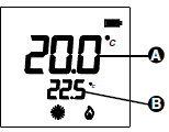
- The display shows the set-point temperature on the large digits (A ) by pressing the ‘
 ‘ key or one of the
 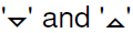 keys, and icon ‘
 ‘ switches on to indicate the set-point temperature is being displayed. The display also shows the icon relating to the regulation mode to which the displayed set-point temperature refers.
 - Press ‘ ‘ to display the set-point temperature of the other regulation modes settable by the user.
- Press to modify the display set-point temperature.
- Adequately configure parameters P15, P16, P17 and P18 to prevent the installer from modifying one or more set-points (see the ‘INSTALLER CONFIGURATION’ paragraph for further information).
CONTROL OF A SECOND STAGE
The thermostat can be configured to drive two heating systems, useful in rooms with two heating systems: a main one and a secondary one (second stage), e.g. a bathroom with radiant floor main heating and one towel rail warmer as secondary system. In a perspective of energy saving, the thermostat uses the main heating system and, only when required, the second stage. It will only switch-on the towel rail warmer when the room temperature is below the wanted set-point by a specified value (Δ set-point) in parameter P29, this way operating as an integration of the main floor heating. Furthermore, the second stage can be forced on together with the main heating in ‘Boost’ regulation mode. Both heating systems will be switched on to reach the set-point temperature by setting the regulation mode in Boost. By setting the regulation mode in Economy, the second stage always remains off, as it is a saving mode. Configure parameter P02 on ‘Yes’ and customise the integration set-point Δ on parameter P29, if the thermostat is desired to drive the second stage. Once the thermostat is set to drive the second stage, it will transmit to two different receivers or to two channels of the same receiver. The main channel is normally acquired by activating the ‘test’ function by simultaneously pressing the ‘3’ and ‘ ‘ keys. The second stage channel is acquired by activating the second stage ‘test’ function: once the main channel’s ‘test’ function is activated (‘3’ and ‘![]() ‘), press ‘ ‘, the small digits will show the writing “2OUt”. Then proceed with self-leaning of the second stage channel on the receiver.
‘), press ‘ ‘, the small digits will show the writing “2OUt”. Then proceed with self-leaning of the second stage channel on the receiver.
EXTERNAL NTC SENSOR
The thermostat has one input for connecting an external NTC sensor (optional) and an internal sensor. The external sensor can be used to detect the room temperature if the thermostat is to be installed in an unsuitable position for room temperature detection. Alternatively, the external sensor can be configured to measure the floor temperature, useful in floor heating systems. With external sensor on floor, the thermostat can consider a minimum and maximum floor temperature limit during the room temperature regulation. For example, a lower limit can be set in heating to which the floor must not drop in order to avoid feeling a cold floor, while a maximum limit can be set, beyond which the floor must not go, to guarantee maximum wellbeing. The thermostat gives priority to the temperature limits within which the floor must remain. The thermostat signals by flashing the ‘ ‘ symbol on display when it is regulating to maintain within the floor temperature limits. By pressing ‘ ![]() ‘, the thermostat can be configured so that the measured floor temperature can be shown on display (see the ‘INSTALLER CONFIGURATION’ paragraph for further information).
‘, the thermostat can be configured so that the measured floor temperature can be shown on display (see the ‘INSTALLER CONFIGURATION’ paragraph for further information).
RADIO SYSTEM CONFIGURATION
Check if the receiver to be coupled with the thermostat is compatible reading the “COMPATIBILITY WITH NEW WAVE RADIO SYSTEM” paragraph. Check that the receiver correctly receives the wireless thermostat’s signals before installing it in the wanted position. The operation is carried out by activating the ‘Test’ function by simultaneously pressing ‘3’ and ‘ ‘. The thermostat displays the writing ‘TEST’ and continuously transmits switch-on and off controls to the receiver, with a 2 second pause between them, in ‘Test’ mode; the symbol ‘ ‘ on the display switches on every time the thermostat transmits a radio control. The ‘Test’ mode can be ended at any time by pressing ‘ ‘. However, the ‘Test’ mode automatically ends after approx. 17 minutes. The ‘Test’ mode must be used to self-learn the thermostat address on the receiver and, subsequently, the relative output’s relay in the receiver, must continuously switch-on and off every 2 seconds; the relative LED also indicates the status. If so, the thermostat correctly communicates with the receiver. Ensure the two devices still correctly communicate when positioning the thermostat in the wanted area. The output relay always remains on or off if the thermostat is positioned too far from the receiver: if so, we recommend finding a better position, maybe closer to the receiver, and ensure it is not near metal screens or reinforced concrete walls that might weaken radio signal. The signal quality can be monitored in the receiver (see the relative documentation for further information).
ASSOCIATION WITH A PROGRAMMABLE THERMOSTAT
In a New Wave radio system, consisting of a multi-channel receiver module, a programmable thermostat and other simple thermostats, is possible to regulate the room temperature by the latter, according to the time program of the programmable thermostat. This can be obtained by associating the outputs controlled by the thermostats on the receiver, to the programmable thermostat ones. This way, a timer thermostat and the thermostats associated to it, form an ‘area’. For example, a day area and a night area can be created in a home, with regulation on several rooms based on the different programmable hourly bands on two programmable thermostats. The associated channels receive information from the programmable thermostat of which regulation mode to use and therefore, which temperature to work, comfort or economy, off or antifrost. If the programmable thermostat is working at a Comfort temperature, the associated thermostats work according to their Comfort set-point; whereas, if the programmable thermostat is working at economy temperature, the associated thermostats work with their economy temperature. Similarly, if the programmable thermostat is off with antifrost function at 5°C, the associated thermostats also regulate the antifrost temperature at 5°C. The display thermostat can also have the output associated to a programmable thermostat and, when set in ‘Auto’ mode, the receiver regulates with the regulation mode received from the programmable thermostat. The P01 parameter must be set at ‘rEC’, if it is desired to use the thermostat in association with a programmable thermostat. See the receiver instructions for the association procedure.
INSTALLER CONFIGURATION
The installer configuration allows defining the thermostat operation to regulate it to the different types of rooms andsystems. Holdsimultaneously pressed for a few seconds until the “key” symbol and the writing “COn” (configuration) appear on the display, to access configuration. Pressing ‘ ‘ from now, scrolls the different installer parameters identified with ‘P’ and by the parameter number, from P01 to
P29.
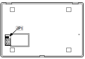
Configuration end is indicated with the wording ‘End’. Press ‘![]() ‘ again to save configuration and the thermostat switches to normal operation. Exit the configuration menu without saving the changes at any moment by pressing ‘ ‘. The large display digits show the parameter’s number and the small ones the parameter’s title, while scrolling the parameters. By pressing ‘ ‘ or ‘ in this phase, the large display digits show the current parameter setting. Use keys to modify the selected parameter’s configuration; the value is quickly increased or decreased by holding the keys pressed. The ‘test’ procedure is automatically activated after configuration end and saving. During this test, the thermostat communicates information on the output configuration to the receiver, which the latter saves in a versatile way and is used to regulate the temperature in the desired mode. It is important, therefore, to run self-learning procedure on the receiver before modify the configuration; and it is important to check that the receiver correctly receives the ‘test’ controls at the end of the configuration. Remove the jumper (JP1) indicated in Fig. 4 to prevent configuration access to unauthorised users; the display shows an error message if configuration access is attempted.
‘ again to save configuration and the thermostat switches to normal operation. Exit the configuration menu without saving the changes at any moment by pressing ‘ ‘. The large display digits show the parameter’s number and the small ones the parameter’s title, while scrolling the parameters. By pressing ‘ ‘ or ‘ in this phase, the large display digits show the current parameter setting. Use keys to modify the selected parameter’s configuration; the value is quickly increased or decreased by holding the keys pressed. The ‘test’ procedure is automatically activated after configuration end and saving. During this test, the thermostat communicates information on the output configuration to the receiver, which the latter saves in a versatile way and is used to regulate the temperature in the desired mode. It is important, therefore, to run self-learning procedure on the receiver before modify the configuration; and it is important to check that the receiver correctly receives the ‘test’ controls at the end of the configuration. Remove the jumper (JP1) indicated in Fig. 4 to prevent configuration access to unauthorised users; the display shows an error message if configuration access is attempted.
Reset installer configuration
Reset installer configuration in order to bring all parameters to default values by accessing configuration and, when the display shows ‘Con’, simultaneously press ![]() for a few seconds until the screen goes back to normal display.
for a few seconds until the screen goes back to normal display.
Description of configuration parameters
The installer configuration parameters are shown in table 1 and explained below.
ATTENTION
Some installer parameters may not be displayed as only current configuration required parameters are proposed (the way of configuring a parameter, may exclude one or more subsequent parameters).
- P01 (HC_S): allows to use the thermostat (trA) or receiver (rEC) in heating/cooling mode. This parameter must only be modified to ‘ rEC ‘ (receiver) when wanting to use the thermostat in association with a programmable thermostat in a New Wave radio system or the external heating/cooling selection input of the New Wave relay modules. The heating/cooling setting must be left on the thermostat (parameter setting on ‘ trA ‘), if it is desired to use the special function ‘second stage’.
- P02 (2OUt): allows activating (YES) or deactivating (no) the second stage control. See the “CONTROL OF A SECOND STAGE” paragraph.
- P03-P07 (MCOM – comfort mode, MbSt – boost mode, MrEd – economy mode, MOFF – switch-off mode, MAUt – automatic mode): these five parameters allow customising the room temperature’s regulation mode, selectable using the ‘ ‘ key and the thermostat switch-off. Each regulation mode can be configured with the following values:
- no: regulation mode not active, it cannot be selected using the ‘ ‘ key.
- YES: regulation mode active, it can be selected using the ‘ ‘ key.
- tMO: regulation mode active, it can be selected using the ‘ ‘ key but it temporary: the thermostat goes back to default regulation mode (settable by means of parameter P09) upon countdown time-out (settable by means of parameter
- no: regulation mode not active, it cannot be selected using the ‘
- P08). The user can modify time-out with keys ‘3’ or ‘4’. tFI: regulation mode active, can be selected using the ‘ ‘ key but it’s temporary: the thermostat goes back to default regulation mode (settable with the parameter P09) upon countdown time-out (settable with the parameter P08). The user cannot modify the time-out.
- P08 (tOUt): time-out of the temporary regulation modes. Countdown starts from the value set in this parameter, as soon as temporary regulation mode is set. Time can be set from 10 minutes to 24 hours, with 10 minute steps. Time-out is displayed in ‘hours.minutes by 10’ format, e.g. 2.3 means 2 hours and 30 minutes.
- P09 (MdEF): default regulation mode. Mode in which the thermostat returns upon temporary mode time -out. One of the following can be chosen: Comfort, Economy, OFF/Antifrost or Auto as long as (P03-P07) have been set to active, in previous parameters.
- P10 (OFS): room temperature offset. The detected room temperature can be correct by ±10.0 °C with the offset, in order to correct any systematic reading errors due to thermostat positioning in unsuitable areas for detection of the room temperature. By default the device is set with 0.0 °C offset.
- P11 (SPHL) and P12 (SPHU): these two parameters configure the temperature range within which the set-point temperature can be set when the thermostat is in heating mode. P11 is the lower limit and can be freely configured from 5.0 .. 35.0 °C, while
- P12 is the higher limit that can be configured in a range from the lower limit, chosen in P11, up to 35.0°C. Therefore, the maximum range is 5 .. 35 °C and can be easily reduced based on installation requirements.
- P13 (SPCL) and P14 (SPCU): these two parameters configure
the temperature range within which the set-point temperature can be set when the thermostat is in cooling mode, with the same logic of the previous two points. The set-point temperature limits are re-defined upon changing of the cooling/heating setting. In the event the cooling/heating selection is on the receiver (P01=rEC), these two parameters will not be used and the settings of parameters P11 and P12 are always used. - P15-P18 (SCOM – comfort mode, – SbSt – boost mode, SrEd – economy mode, SAFr – antifrost mode): allows choosing whether the relative set-point temperature, of each regulation mode, can be modified by the user by means of keys ‘3’ or ‘4’ or blocked so user action is limited.
- P19 (Entc): external NTC sensor configuration, the parameter can be set with the following values:
- ‘no’: No external sensor connected.
- ‘rOO’: External sensor connected to detect room temperature.
- ‘FLH’: External sensor connected to detect floor temperature, but is not shown on display.
- ‘FLS’: External sensor connected to detect floor temperature that can be shown on display.
- P20 (LinF) floor temperature lower limit and P21 (LSUP) floor temperature upper limit. A minimum and maximum floor temperature can be set in these parameters, in the event the external sensor is connected and configured to detect the floor temperature. The floor temperature lower limit can be set in the range 10 .. 30 °C, while the upper limit in the range 20 .. 50°C. The limits can be disabled by configuring the limit below the minimum value, until “no” appears. The device is default set with limits disabled.
- P22 (OPWM): output PWM regulation, allows choosing whether the receiver output must be driven in ON/OFF or PWM (Pulse Width Modulation) mode. regulation mode (settable by means of parameter P09) upon countdown time-out (settable by means of parameter P08). The user can modify time-out with keys ‘3’ or ‘4’. tFI: regulation mode active, can be selected using the ‘ ‘ key but it’s temporary: the thermostat goes back to default regulation mode (settable with the parameter P09) upon countdown time-out (settable with the parameter P08). The user cannot modify the time-out. P08 (tOUt): time-out of the temporary regulation modes. Countdown starts from the value set in this parameter, as soon as temporary regulation mode is set. Time can be set from 10 minutes to 24 hours, with 10-minute steps. Time-out is displayed in ‘hours.minutes by 10’ format, e.g. 2.3 means 2 hours and 30 minutes.
- P09 (MdEF): default regulation mode. Mode in which the thermostat returns upon temporary mode time-out. One of the following can be chosen: Comfort, Economy, OFF/Antifrost or Auto as long as (P03-
- P07) have been set to active, in previous parameters.
- P10 (OFS): room temperature offset. The detected room temperature can be corrected by ±10.0 °C with the offset, in order to correct any systematic reading errors due to thermostat positioning in unsuitable areas for detection of the room temperature. By default the device is set with 0.0 °C offset.
- P11 (SPHL) and P12 (SPHU): these two parameters configure the temperature range within which the set-point temperature can be set when the thermostat is in heating mode. P11 is the lower limit and can be freely configured from 5.0 .. 35.0 °C, while
- P12 is the higher limit that can be configured in a range from the lower limit, chosen in P11, up to 35.0°C. Therefore, the maximum range is 5 .. 35 °C and can be easily reduced based on installation requirements.
- P13 (SPCL) and P14 (SPCU): these two parameters configure the temperature range within which the set-point temperature can be set when the thermostat is in cooling mode, with the same logic of the previous two points. The set-point temperature limits are re-defined upon changing of the cooling/heating setting. In the event the cooling/heating selection is on the receiver (P01=rEC), these two parameters will not be used and the settings of parameters P11 and P12 are always used
- P15-P18 (SCOM – comfort mode, – SbSt – boost mode, SrEd – economy mode, SAFr – antifrost mode): allows choosing whether the relative set-point temperature, of each regulation mode, can be modified by the user by means of keys ‘3’ or ‘4’ or blocked so user action is limited.
- P19 (Entc): external NTC sensor configuration, the parameter can be set with the following values:
- ‘no’: No external sensor connected.
- ‘rOO’: External sensor connected to detect room temperature.
- ‘FLH’: External sensor connected to detect floor temperature, but is not shown on display. ‘FLS’: External sensor connected to detect floor temperature that can be shown on display.
- P20 (LinF) floor temperature lower limit and P21 (LSUP) floor temperature upper limit. A minimum and maximum floor temperature can be set in these parameters, in the event the external sensor is connected and configured to detect the floor temperature. The floor temperature lower limit can be set in the range 10 .. 30 °C, while the upper limit in the range 20 .. 50°C. The limits can be disabled by configuring the limit below the minimum value, until “no” appears. The device is default set with limits disabled.
- P22 (OPWM): output PWM regulation, allows choosing whether the receiver output must be driven in ON/OFF or PWM (Pulse Width Modulation) mode. Customisable hysteresis regulation on parameter
- P24 will be had with ON/OFF regulation, while a proportional regulation will be had with PWM regulation (YES) that can be adapted to the different room with proportional band, additional time and cycle time parameters.
- P23 (EOrM): extends drive mode of output to other channels; this parameter is only significant if the thermostat is paired with a more channel receiver (DLP —). If this parameter is set on ‘YES’, all receiver channels will be configured with ON/OFF or PWM setting chosen in parameter
- P22 and relative parameters from P24 to P28 hysteresis, proportional band, additional time and cycle time. This way, the thermostat can be used to configure the output drive mode on the channel on which self-learning was made and on the other channels also available on the receiver. For example, the receiver hysteresis can be changed in this mode or make an output become PWM, even if the channel will then be driven by a simple, not configurable, thermostat.
- P24 (HYSt): hysteresis, it represents the hysteresis width used when an ON/OFF regulation (no) is chosen in P22 or when the thermostat limits the floor temperature.
- P25 (BP): PWM proportional band, it is used for proportional regulation when the output is configured in P22, to be driven with PWM (YES).
- P26 (t int): additional time in minutes, it is used for proportional regulation when the output is configured in P22, to be driven with PWM. If set to zero, this parameter prevents to have any action.
- P27 (PCYC): PWM cycle time, it is the duration of each PWM cycle in minutes, meaning every how many minutes is the variable width impulse repeated.
- P28 (PM In): minimum time of PWM ON, meaning the minimum PWM impulse width or the minimum output switch-on time. This parameter must be set with the actuator’s opening time, in the event an electro-thermal actuator is connected, otherwise switches for lower times respect to opening time, do not generate significant output actions.
- P29 (dSPI): this parameter allows setting the integration setpoint Δ of the second stage (see the ‘Control of a second stage’ paragraph for further information).
DIMENSIONS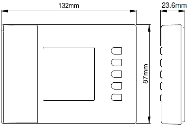
WARRANTY
In view of the constant development of their products, the manufacturer reserves the right for changing technical data and features without prior notice. The consumer is guaranteed against any lack of conformity according to the European Directive 1999/44/EC as well as to the manufacturer’s document about the warranty policy. The full text of the warranty is available on request from the seller.
REFERENCE:
DOWNLOAD MANUALS:
ESBE TPD214 WIRELESS DIGITAL THERMOSTAT Operating Manual
![]()