
Emos SARV105 WIRELESS THERMOSTAT
INTRODUCTION
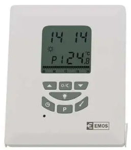
This thermostat can replace most common residential thermostats and is designed to be used to control heating or cooling system. Unlike ordinary single unit design thermostats, this unit is a new type of thermostat separating the thermostat function into two units. The Receiver serves for wiring connections and heat/cool on/off control. The Control Centre serves as user interface and temperature sensing/control. The two units are linked by RF. The advantage is that users can put the Control Centre nearby and can read/control the temperature of the living area.
Caution
- The appliance can only be mounted indoors and in areas free from any water or moisture.
- A suitable fuse with a rating not exceeding 20A should be placed in the power line.
- Observe the national regulations for wiring.
- A qualified electrician is recommended for installation and servicing.
- Read this manual carefully before installing.
SPECIFICATION
- Switching load: max. 230V AC; 16A resistive; 5A inductive
- Clock accuracy: +/ – 60 seconds/month
- Temp. measurement: 0°C to 40°C in 0.2°C resolution
- Temp. accuracy: +/ – 1°C at 20°C
- Temperature Control: 7°C to 30°C in step of 0.2°C
- Span: 0.4, 0.8,1.4 or 1.8°C
- Air conditioner cycle time: 3 minutes
- Operation temperature: 0°C to 40°C
- Storage temperature: -10°C to 60°C
- Frequency: 868MHz
- Range: 70m in open area
- Power Source: Control Centre 2x 1.5V AA (LR6) batteries
- Receiver 230V AC 50Hz
- Size and Weight: Control Centre 116 x 100 x 23.5mm, 126g
- Receiver 97 x 128 x 37mm, 190g
Control Centre
- Can be placed anywhere in the home to detect and control the temperature of an area of the user’s choice. Not limited by power control wiring locations.
- Link with the Receiver via RF. Control distance 70M open site
- LCD shows the “need to know” information only, which is easier to understand: Real time clock with day of the week display
- Room temperature display Control profile display
- Simplified temperature adjustment and programming procedure
- 6 pre-defined control profiles, 3 user programmable control profiles
- Protection against freezing
- Temporary set-temperature override
- User selectable temperature span;
- User selectable heater/cooler operation mode
- Slim housing design
- EL backlight.
Removing of back housing of Control Centre
- Push and hold internal lock by a screw driver.
- Remove the front housing.
- Receiver (Power Control Unit)
LED INDICATORS
There are two LEDs on the Power Control Unit as status indicators:
- Red LED turns on as long as there is power to the unit. When there is no power to the unit or when power switch on the front cover is put at the OFF position, the red LED is off.
- Green LED turns on as long as the heating/cooling device is energized.
POWER SWITCH
There is a power switch on the Power Control Unit. When there is no demand to turn on the heating/cooling device, e.g. when you go on holiday, it is recommended to turn the power switch to the OFF position.
INSTALLATION
RF Address Code Setting
- If there is another user nearby, e.g. in the next house, your receiver may be faulty triggered by their transmitter.
- You may select a different RF address code to prevent this. Receiver can only response to RF coding with the same address code setting as its own address code.
- To adjust address code of Power control unit, simply left or right of the 5 dip switch levers.
- To adjust address code of Control Centre, open the housing of the transmitter unit. See removing of back housing of Control Centre section on how to open the housing.
Caution:
- Address code of Control Centre must be the same as address code of Receiver.
- For any ON position of address code # in Control Centre, the same address code # of Receiver must be switched to ON.
- Disconnect AC power and remove batteries prior to adjusting address code.
Removing your old thermostat
Read the following instructions carefully before disconnecting the wires.
- Turn off your old thermostat.
- Remove the cover from the old thermostat.
- Unscrew the old thermostat from the wall plate.
- Now find the screws attaching the wall plate to the wall, and remove them.
- You should now be able to pull the wall plate a small distance from the wall. Do not disconnect any wire yet, simply locate the wires.
WARNING: After removing the wall plate, if you find that it is mounted on a junction box (e.g. a box similar to one behind a light switch or electric outlet), high voltage circuit may be present and there is a danger of electric shock. Please consult a qualified electrician.
Choosing a Location
Note: for a new installation, choose a mounting location about five feet (1.5 meters) above the floor in the area with good air circulation and away from:
- Drafts.
- Air ducts.
- Radiant heat from the sun or appliances.
- Concealed pipes and chimneys.
Mounting the Receiver onto the wall
- Remove the back plate from the Receiver.
- Mark the holes position.
- Drill two holes and insert the plastic anchors carefully into the holes, fasten the back plate to the wall with 2 screws.
- Connect the wires – see wiring diagram.
- Push on the wires in the wall.
- Securely fasten the Receiver to the back plate.
Wiring diagram
RECEIVER WIRING TERMINALS
- NO switch terminal – Normally opened
- COM switch terminal
- L Live feed 230V AC
- N Neutral
Mounting the Control Centre onto the wall (if you don’t need to use its mobility)
- Remove the back housing of the Control Centre.
- Mark the holes position.
- Drill two holes and insert the plastic anchors carefully into the holes, fasten the back housing to the wall with 2 screws.
- Securely fasten the Control Centre to the back housing.
SETTING OF CONTROL CENTRE
Heater/Cooler Selection
Before making any selection in the Control Centre, its back housing must be removed. Inside the Control Centre after the back housing is removed, you can find 3 DIP switches. These three switches are used to control the span and heat/cool system. Set the DIP switch (position 3) according to your selection of heater system or cooler system according to the following diagram. Switch no. 3
Temperature Span Selection
Span is the temperature difference between the turn on temperature and turn off temperature. For example, in heating systems, if you set temperature to 20°C and span to 0.8°C, the heater will operate when the room temperature drops to 19.2°C and turns off when the temperature rises to 20.8°C. Set the DIP switch (position 1 & 2) according to your selection of temperature span as the following diagram.
Battery Installation
- Your thermostat uses two “AA” size batteries to operate.
- To power-up the unit, insert two “AA” batteries into the battery compartment of the front housing. When power is applied for the first time, the display must show time and the day as well as the room temperature.
- If the display is different, press the RESET button. Use a fine probe such as straightened paper clip to gently push the RESET button.
- After installation of the batteries, push back the rear housing to the Control Centre and then the stand. Before turning on the main switch of the system, press the reset button once. The thermostat is ready for use.
Testing the RF Transmission Range
- Press UP button until the set-point temperature is higher than room temperature by a few degrees.
- Wait for a few seconds.
- Check the green LED on the Receiver. It should be ON.
- If the LED is not ON, try to place the Control Centre closer to the Receiver. Press the Down button to adjust the set-point temperature to be lower than room temperature to “turn off” the receiver.
- Repeat steps 1 to 4.
- The receiving range between Control Centre and Receiver is 70M in open area. When placed indoors, this distance may be shorter because of blocking by concrete walls etc, but is enough for most household applications.
- Press RESET button after testing of receiving range.
Setting Clock
- Press the SET TIME button to clear all digits except the day indicator and the time display. The day indicator is flashing.
- While day indicator is flashing, press UP or DOWN button to adjust.
- Press the SET TIME button again, hour digits are flashing instead of day indicator.
- Press UP or DOWN button to adjust. Press and hold the UP or DOWN button to speed up the adjustment rate.
- Press the SET TIME button again, minute digits are flashing instead of hour digit.
- Press UP or DOWN button to adjust. Press and hold the UP or DOWN button to speed up the adjustment rate.
- Press the SET TIME button again to return to normal operation mode.
- The unit will return to normal operation mode if no key is pressed for 15 seconds.
Setting Control Temperature
- Press the SET TEMPERATURE button to display the pre-defined set temperature.
- Press the CONF/ECON button to toggle between the setting of economic mode and comfortable mode.
- Press the UP or DOWN button to increase/decrease the set temperature by 0.2°C.
- Press the SET TEMPERATURE button again to save the set temperature.
- The unit will return to normal operation mode if no button is pressed for 15 seconds.
- The default setting of comfortable mode is 21°C for heater mode and 23°C for cooler mode. The economic mode is
for heater mode and 26°C for cooler mode.
PROGRAM SETTING
- Select Week-Day
- Press the SET PROGRAM button, the day indicator shows the program day and is flashing. Program number indicator shows the current program for the selected day.
- Press the UP or DOWN button to select the day needed to program. You can select the whole week, working week, weekend or individual day to program.
Select Control profile
- Press the SET PROGRAM button again, the day indicator stops flashing and the program number starts to flash.
- Press the UP or DOWN button to select the program profile. P1-P6 are predefined programs. Their profiles are shown as below
- If any of these programs are selected, press the SET PROGRAM button again to confirm this program for the specified day and return to normal operation mode.
- If user-defined programs P7-P9 are selected, press the CONF/ECON button to toggle the control temperaturesetting and advance the setting hour digit by one.
- Press the “P” button to terminate the setting procedure and to return to normal operation mode.
- The setting procedure will terminate automatically when no button is pressed for 15 seconds.
TEMPORARY OVERRIDE
Override the Operation Mode
At the normal operation mode, press the CONF/ECON button to toggle the current set temperature to comfortable mode or economic mode. If the operation mode is being overridden, the HAND icon will be turned on with the current operation mode icon.
Override the Temperature Setting
- In the normal operation mode, the current set temperature can be overridden by pressing the UP or DOWN button.
- When temperature is being overridden, the new set temperature will be displayed with the HAND icon and with both the CONF and ECON icons turned off.
- Press any button (except the UP or DOWN button), this will terminate the setting procedure and will revert back to normal mode with the new setting.
- The unit will revert to normal operation mode automatically when no button is pressed for 15 seconds.
ANTI-FREEZING MODE
- Pressing the UP and DOWN buttons simultaneously will activate the anti-freezing mode (for heater mode only).
- The ANTIFREEZING icon and the HAND icon will be turned on while both the COMF and ECON icon will be turned off.
- Pressing any button will terminate the anti-freezing mode and revert to normal operation mode.
- The default set temperature for the anti-freezing mode is 7°C.
BACKLIGHT
Press the BACKLIGHT button to turn on the backlight. The backlight will switch off when no button is pressed for 15 seconds.
BATTERY REPLACEMENT
- It is recommended that the batteries should be replaced when the display is showing the battery-low icon. To replace the battery:
- Turn off the power of the Receiver first.
- Remove the back housing and stand of the Control Centre.
- Replace the old batteries with 2 new AA alkaline batteries.
- Replace the back housing and stand.
- Press the reset button once and then turn on the power switch of the Receiver.
Disclaimer: The Control Centre and the Receiver contain no user-serviceable parts. The information in this document has been viewed and is believed to be accurate. However, neither the manufacturer nor its affiliates assume any responsibility for inaccuracies, errors or omissions that may be contained herein. In no event will the manufacturer or its affiliates be liable for direct, indirect, special, incidental or consequential damages arisen by using this product or resulting from any defect/omission in this document, even if advised of the possibility of such damages. The manufacturerand its affiliates reserve the right to make improvements or changes to this document and the products and services described at any time, without notice or obligation. Hereby, Emos spol. s r. o., declares that this SARV105 is in compliance with the essential requirements and other relevant provisions of Directive 1995/5/EC. Declaration of conformity is enclosed in manual or web sites www.emos.eu
Reference
Download Manual:
Emos SARV105 WIRELESS THERMOSTAT User Manual