Emerson 1F83H-21PR Programmable Thermostats
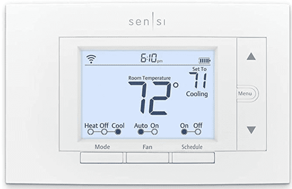
THERMOSTAT INSTALLATION
MERCURY NOTICE: This product does not contain mercury. However, this product may replace a product that contains mercury. Mercury and products containing mercury must not be discarded in household trash. Refer to www.thermostat-recycle.org for information on disposing of products containing mercury.
|
Thermostat Applications |
Maximum Stages Heat/ Cool |
| Single Stage Compressor, Heat Pump Systems (air source or geothermal)
– 1 Stage Aux/Emergency Heat, Electric or Gas (Dual Fuel) |
2/1 |
SPECIFICATIONS
| Electrical Rating: | |||
| Battery Power | 20 to 30 VAC, NEC Class II, 50/60 Hz | ||
| Input- Hardwire | 20 to 30 VAC, NEC Class II, 50/60 Hz | ||
| Terminal Load | 1.5 A per terminal, 2.5A maximum all terminals combined | ||
| Setpoint Range | 45° to 99° F (7° to 37° C) | ||
| Rated Differentials (@ 6° F/ Hr): |
Fast |
Med |
Slow |
| Heat Pump (Heat) | 0.9°F | 1.2°F | 1.7°F |
| Heat Pump (Cool) | 0.9°F | 1.2°F | 1.7°F |
| Auxiliary Heat | 0.5°F | 0.75°F | 1.9°F |
| Operating Ambient | 32°F to +105°F (0° to +41°C) | ||
| Display Temperature Ran ge |
32°F to +99°F (0 to 37°C) |
||
| Operating Humidity | 90% non-condensing maximum | ||
| Shipping Temperature Ra nge |
-20°F to + 150°F (-29° to +65°C) |
||
| Thermostat Dimensions | 3-3/4” H x 6” W x 1-1/8” D | ||
WIRING
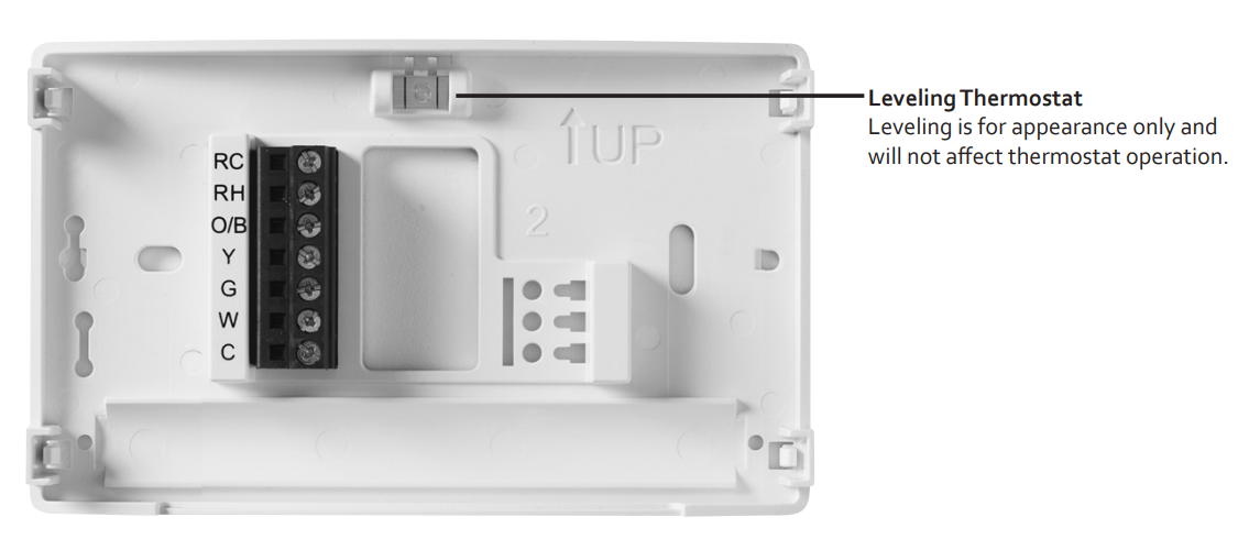
Refer to equipment manufacturer’s instructions for specific system wiring information. After wiring, see INSTALLER MENU for proper thermostat configuration. The wiring table shown is for typical systems and describes the thermostat terminal functions
| Terminal Designations |
Terminal Function |
| R | Power (24V) |
|
O/B |
Changeover Terminal-Energized in Cool (O) or Heat (B) for Heat Pump or Damper Syst ems |
| Y | Heat and Cool Mode 1st Stage Compressor |
| G | Fan Relay |
| E* | Auxiliary only Heat Mode (Emergency Heat) |
| C | Common wire for 24V (optional with batteries) |
| L | Heat Pump malfunction / Diagnostic terminal (input signal requires common) |
| W2* | Heat Mode – 2nd stage |
Cut W2/E jumper when separate heat sources are used for W2 and E.
Precautions
- Do not exceed the specification ratings.
- All wiring must conform to local and national electrical codes and ordinances.
- This control is a precision instrument and should be handled carefully. Rough handling or distorting components could cause the control to malfunction
- Do not use on circuits exceeding specified voltage.
- Higher voltage will damage control and could cause shock or fire hazards.
- Do not short out terminals on gas valve or primary control to test.
- Short or incorrect wiring will burn out the thermostat and could cause personal injury and/or property damage.
Battery Location
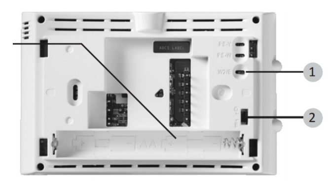
Premium AA alkaline batteries are required when C-wire is not available. When C-wire is available, the batteries provide a backup source of power (this will maintain the clock in the event of a power outage
- W2/E Jumper Wire This thermostat electrically connects the W2 and E terminals so that you do not need to do this with a jumper wire. If your system has separate W2 and E wires, clip the W2/E jumper located on the back of the thermostat. This will isolate both terminals so they can be used independently.
- O/B Terminal Switch The O/B switch on this thermostat is factory set to the O position. This will accommodate the majority of heat pump applications, which require the changeover relay to be energized in Cool. If the heat pump is installed requires a B terminal to energize the changeover relay in Heat, the O/B switch must be moved to the B position.
To prevent changes that may affect system performance, this thermostat has an INSTALLER’S MENU and a USER MENU. The INSTALLER’S MENU provides access to every option, while the USER MENU provides access to items that will not affect system performance. To access the INSTALLER’S MENU press the Menu button for 8 seconds. The display will show item 30 in the table below. Use Next and Back to navigate through menu items. Press  to change a menu setting.
|
Installer’s Menu # (Hold Menu 8 Seconds) |
Description |
Default Setting (flashing icons) |
Settings (Press
) |
30
|
Heat Cycle Rate (how oft en the heat will turn on) |
MEd |
SLO – slow MEd – medium FAS – fast |
| 32
|
Aux Cycle Rate (how oft en the auxiliary heat will turn on) |
MEd |
SLO – slow MEd – medium FAS – fast |
| 35
|
Cool Cycle Rate (how oft en the cooling will turn on) |
MEd |
SLO – slow MEd – medium FAS – fast |
| 50
|
Compressor Lockout (protects the compressor from short cycling) |
OFF |
On – 5 minute delay OFF – no delay |
60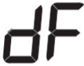
|
Duel Fuel Logic (turn On when using gas as the au xiliary heat source) |
OFF |
On-gas auxiliary heat OFF- electric auxiliary h eat |
|
65 |
Maximum Heat Limit (maximum set point for he at mode |
99 |
47 to 99 |
|
66 |
Minimum Cool Limit (minimum set point for co ol mode) |
45 |
45 to 97 |
|
74 |
Schedule Type (set as eit her 7-Day5-1-1 Day or No n-Programmable) |
5 |
7 – 7 Day
5 – 5-1-1 Day 0 – Non-Programmable |
|
76
|
Early Start (starts heating or
cooling early so you progr ammed temperature is reached by the programmed time) |
OFF |
On – start early OFF – start at program pe riod time |
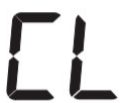

|
79 |
Fahrenheit or Celsius |
°F |
°F – Fahrenheit
°C – Celsius |
|
81 |
Temperature Display Ad justment (adjust the displ ayed “Room Temperature ”) |
0 |
-5 to +5 |
| 83
|
Continuous Display Lig ht (keep the backlight always on – “C” wire required) |
OFF |
On – always on OFF – momentarily |
|
86 |
Change Air Filter (set up a monthly
reminder) |
OFF |
1 to 12 – reminder time (months) |
| 99
|
Keypad Lock (prevent un wanted changes to the thermostat ) |
OFF |
OFF – no filter reminder On – disable buttons OFF – all buttons are acti ve |
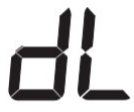

TEST EQUIPMENT
Turn on power to the system.
Fan Operation
- If your system does not have a G terminal connection, skip to Heating System.
- Move fan switch to On position. The blower should begin to operate.
- Move fan switch to the Auto position. The blower should stop immediately.
Heating System
- Move System Switch to Heat position. If the auxiliary heating system has a standing pilot, e sure to light it.
- Press
 to adjust thermostat setting to 1° above room temperature. The heat pump system should begin to operate and the thermostat will indicate Heat On.
 - Press
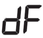 to adjust thermostat setting to 3° above room temperature. The auxiliary heat should begin to operate and the thermostat will indicate Heat On Auxiliary.
 - Press to adjust the thermostat setting 1° below room temperature. The heating system should stop operating and the thermostat should indicate Heat.
Auxiliary System
- Move System Switch to Aux position. If the auxiliary heating system has a standing pilot, be sure to light it.
- Press to adjust thermostat setting to 1° above room temperature. The auxiliary heating system should begin to operate and the thermostat will indicate Heat On Auxiliary.
- Press to adjust the thermostat setting 1° below room temperature. The auxiliary heating the system should stop operating and the thermostat should indicate Heat Auxiliary.
Cooling System
- Move System Switch to Cool position.
- Press to adjust the thermostat setting 1° below room temperature. The blower should come on immediately at high speed, followed by cold air circulation. The thermostat will indicate Cool On. There can be up to a 5-minute delay. (see INSTALLER MENU, item 50)
- Press to adjust thermostat setting to 1° above room temperature. The cooling system should stop operating and the thermostat will indicate Cool.
USING THE THERMOSTAT
THERMOSTAT OVERVIEW
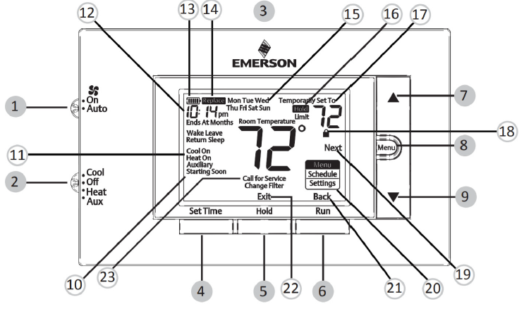
Before you begin using your thermostat, you should be familiar with its features, display, and the location/operation of the thermostat buttons and switches.
| THERMOSTAT BUTTONS AND SWITCHES | THE DISPLAY |
|
1.) Fan Switch |
10.) Thermostat is protecting the equipment from short cycling
(5-minute delay) |
|
2.) System Switch |
11.) Indicates that the system is running in cool, heat o r auxiliary
mode (The auxiliary will run in Heat mode when the he at pump cannot maintain the set temperature.) |
| 3.) Backlight Button (located on the top of the thermostat |
12.) Displays the current time |
| 4.) Set Correct Time | 13.) Battery status indicator |
| 5.) Hold a Permanent Temperature | 14.) Low battery indicator |
|
6.) Cancels Hold – Returns to Programmed Schedule |
15.) Day of the week used when programming a sched ule |
| 7.) Raises Temperature Setting | 16.) Permanent hold (bypassing the schedule) |
| 8.) Access Menu Options | 17.) Temperature setpoint |
|
9.) Lowers Temperature Setting |
18.) Appears when the keypad is locked (to prevent un wanted
changes) |
| 19.) Next (Menu button) is used to navigate within a m enu | |
| 20.) Access the schedule and customize thermostat fe atures | |
| 21.) Back (Run button) is used to navigate within a me nu | |
| 22.) Exit (Hold button) returns to the home screen | |
| 23.) SEE TROUBLESHOOTING |
USER MENU
To customize thermostat settings, press and hold the Menu button for ½ second from the home screen. Use the buttons to highlight Settings and press Next. Use Next and Back to navigate through menu items. Press change the setting.
| User’s Menu #
(Press Menu button and release) |
Description |
Default Setting (flashin g icons) |
Settings (Press or
) |
|
01 |
Schedule Type (set as eit her 7-Day, 5-1-1 Day, or Non-Programmable) |
5 |
7 – 7 Day
5 – 5-1-1 Day 0 – Non-Programmable |
| 02
|
Early Start (starts heating or cooling early so your pr ogrammed temperature is reached by the programm ed time) |
OFF |
On – start early OFF – start at program pe riod time |
| 03
|
Continuous Display Lig ht (keep the backlight alw ays on – “C” wire required ) |
OFF |
On – always on OFF – momentarily |
|
04 |
Change Air Filter (set up a monthly reminder) |
OFF |
1 to 12 – reminder time ( months)
OFF – no filter reminder |
THERMOSTAT OPERATION
Set Current Time and Day
- Press Set Time
- Use to adjust the hour
- Press Next to advance to set the minutes and day of the week
- Press Exit when finished.
The default program is 5-1-1 Day but can be set up as a 7-Day or Non-Programmable thermostat (refer to the User Menu above)
- Hold Temperature (bypassing the schedule) – With the System Switch set to Heat or Cool, momentarily press the Hold button. Hold will be displayed. Use to adjust the temperature. The thermostat will hold the room temperature at the selected setting until you press Run to start the program operation again.
- Program Override (Temporary Hold) – Press until the desired temperature is displayed. The thermostat will override the schedule until the next programmed time period with a minimum override of 2 hours. Then the thermostat will automatically revert to the program.
- Keypad Lockout – To prevent unwanted changes, the buttons can be disabled. To turn this feature On, press and hold and the Menu button until the icon appears. To turn Off, press and hold and the Menu button for 3 seconds
THERMOSTAT SCHEDULE / PROGRAMMING
Energy Saving Factory Schedule
This thermostat is programmed with the energy-saving settings shown in the table below for all days of the week.
| P1/Wake | P2/Leave | P3/Return | P4/Sleep | |
| Heating Schedule | 6:00 AM – 70°F | 8:00 AM – 62°F | 5:00 PM – 70°F | 10:00 PM – 62°F |
| Cooling Schedule | 6:00 AM – 78°F | 8:00 AM – 85°F | 5:00 PM – 78°F | 10:00 PM – 82°F |
Modify the Heating Schedule
- Slide the system switch to Heat
- Press Menu
- Press Next to enter the schedule
- The time icons will flash – use to set the time for the start of a period
- Press Next – the setpoint icons will flash – use or to set the temperature for the current period
- Continue to press Next to advance through all periods (P1/Wake, P2/Leave, P3/Return,
- Sleep) for all days of the week
TROUBLESHOOTING
| Symptom | Possible Cause | Corrective Action |
| 1.) Blown fuse or tripped circuit b |
1.) Replace fuse or reset the breaker 2.) Turn the switch to ON 3.) Replace the door panel in the proper position to en gage the safety interlock or door switch 4.) Tighten Connections |
|
| reaker | ||
| No Heat/ | 2.) Furnace power switch to OFF | |
| No Cool/ | 3.) Furnace blower compartment | |
| No Fan | door panel loose or not properly i | |
| (common problem) | nstalled | |
| 4.) Lose connection to thermosta | ||
| t or system |
|
No Heat |
1.) System Switch not set to Hea t 2.) Lose connection to thermosta t or system 3.) Heating System requires serv ice or thermostat requires replac ement |
Verify thermostat and system wires are securely attached.
Diagnostic: Set System Switch to Heat and raise the s etpoint above room temperature. Within five minutes t he thermostat should make a soft click sound and “He at On” should appear on display. This sound indicates the thermostat is operating properly. If the thermostat does not click, try the reset operation listed below. If th e thermostat does not click after being reset, contact your heating and co oling service person or place of purchase for a replace ment. If the thermostat clicks, contact the furnace man ufacturer or a service person to verify the heating syst em is operating correctly. |
|
No Cool |
1.) System Switch not set to Coo l 2.) Lose connection to the therm ostat or system 3.) Cooling System requires serv ice or thermostat requires replac ement |
Verify thermostat and system wires are securely attached.
Diagnostic: Set System Switch to Cool and lower setp oint below room temperature. Same procedures as dia gnostic for “No Heat” condition except set the thermost at to Cool and lower the setpoint below the room temp erature. There may be up to a five-minute delay before the thermostat clicks in Cooling if the compressor lock- out option is selected in the installer menu. (see INST ALLER MENU, item 50) |
|
Heat, Cool, or Fan Runs Constantly |
Possible short in wiring, thermostat, heat, cool or fan syst em |
Check each wire connection to verify they are not shor ted or touching other wires. Try resetting the thermosta
t. If the condition persists contact your HVAC service p erson. |
| Thermostat Displa y &
Thermometer Disa gree |
Thermostat display requires adju stment |
The display can be adjusted +/-5°. See User Menu ite m 04 |
|
Furnace (Air Condi tioner) Cycles Too Fast or Slow (narrow or wi de temperature sw ing) |
The location of the thermostat and/ or the size of the Heating S ystem may be influencing the cy cle rate |
Digital thermostats provide precise control and cycle fa ster than older mechanical models. The system turns o n and off more frequently but runs for a shorter time. If you would like to increase cycle time, choose SLO for slow cycle in the Installer menu. (Reference menu ite ms 30 & 35) If an acceptable cycle rate is not achieved
, contact your HVAC service person. |
|
“Call for Service” ic on appears on the display |
1.) Heating system is not able to heat the space to within 10 degr ees of the setpoint within 2 hours 2.) Cooling system is not able to cool the space to within 10 degre es of the setpoint within 2 hours 3.) If “–” is displayed for the Roo m Temperature, a replacement t hermostat is needed
4.) None of the buttons operate on the thermostat 5.) If “Call for Service” is flashing , compressor self-diagnostic is d etecting an issue with the outdoo r unit |
1.) See corrective action for “No Heat” 2.) See corrective action for “No Cool” 3.) Replace the thermostat 4.) Make sure keypad lockout is not turned on (denote
d by the icon) 5.) Contact a service person to verify the equipment is operating correctly |
Resetting the Thermostat or Thermostat Settings
If the thermostat has good batteries, but has a blank display or does not respond to keypresses, the thermostat should be reset by removing the batteries for 2 minutes. This reset will not change the menu settings or program. If the condition persists after reinstalling the batteries, replace the thermostat. To conveniently reset only the schedule and user settings back to factory defaults, press the Menu and Backlight buttons at the same time and hold until the display goes blank and resets.
Reference
DOWNLOAD MANUAL
Emerson 1F83H-21PR Programmable Thermostats Instruction Manual

Emerson 1F83H-21PR Programmable Thermostats Instruction Manual