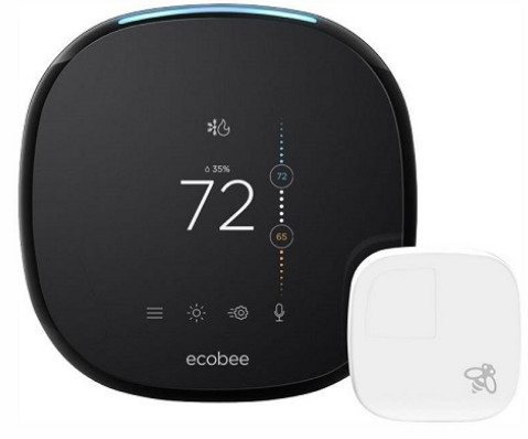
ECOBEE 4 Thermostat
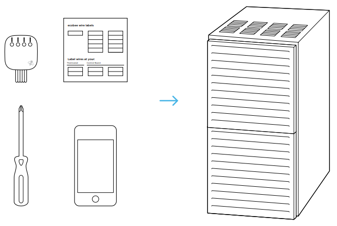
IN THE BOX
You’ll also need these tools
DOWNLOAD
Guide 1 or Guide 2? Start here to find out.
The steps in this section will help you decide which install guide you’ll use to complete the installation.
INSTALLATION
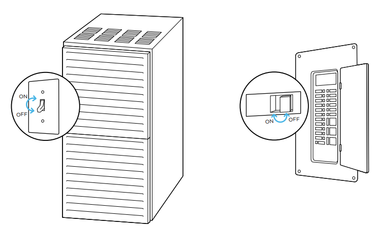
- STEP 1: Power off your Heating, Ventilation, and Air Conditioning (HVAC) system by using the master switch or circuit breaker box. This is important for your safety.

- STEP 2 Confirm your system is off by turning on your heat (during winter) or your AC (during summer). Wait a few minutes—you should not feel air coming from your vents.
 STEP 3 Remove your old thermostat cover from the wall
 CHECKPOINT: COMPATIBILITY
Does your old thermostat’s backplate have any of these indicators?
- STEP4: Take a picture of the wires connected to the terminals of your old thermostat. You may need to reference this photo later on.

CHECKPOINT COMPATIBILITY
Does your old thermostat’s backplate have any of these indicators?
CHECKPOINT: C WIRE
Do you have a C wire connected to your old thermostat?
Install your ecobee with a C wire
- STEP 5: If you have a C wire, it will power your ecobee. You won’t need the Power Extender Kit included in the box.
CHECKPOINT: DON’T SKIP AHEAD
Have you completed steps 1–4 in the ‘Start Your Install’ section?

- STEP 6: Carefully disconnect and label the wires from your old thermostat one at a time, using the labels provided.Unscrew the mounting plate of your old thermostat to remove it from the wall

- STEP 7: Decide if you want to use the trim plate with your ecobee. The trim plate is useful if you want to hide marks or holes left on the wall by your old thermostat.

- STEP 8: If using the trim plate, align the mounting holes on the trim plate and backplate and press them into place together.
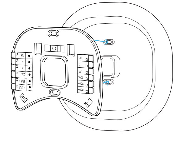
- STEP 9: Pull the wires through the hole in the middle of the backplate and then attach the backplate to the wall using the drywall anchors and screws provided

CHECKPOINT: INSERT YOUR R WIRE(S)
Do you have more than one R wire? (That includes R, Rc, and Rh
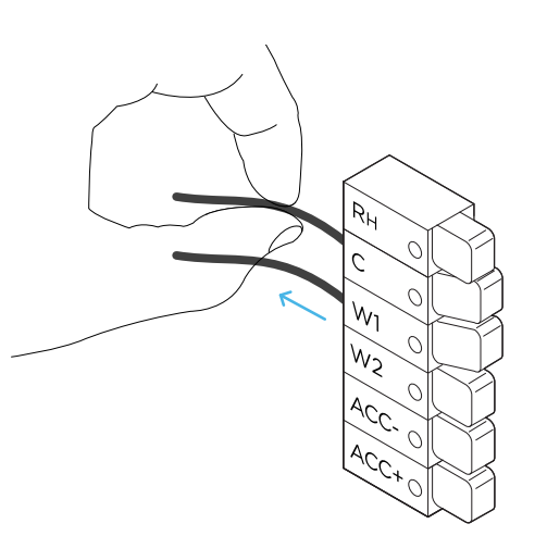
- STEP 10: Insert your remaining wires into the side (not the front) of their corresponding terminal blocks.

- STEP 11: Tug on the wires gently to ensure they are securely connected.

- STEP 12: Carefully push any excess wires back into the hole and ensure there are no drafts coming from the hole(s) in the wall.

- STEP 13: Gently press your ecobee into the backplate until it ‘clicks’ into place.

- STEP 14: Turn the power to your HVAC system back on using the master switch or at the circuit breaker box.
 STEP 15: Say hi to your new ecobee! The screen will power on and guide you through the setup and registration.
Install your ecobee without a C wire
STEP 17: If you don’t have a C wire, you’ll need to use the Power Extender Kit (PEK) included to reliably power your ecobee.
CHECKPOINT: DON’T SKIP AHEAD
Have you completed steps 1–4 in the ‘Start Your Install’ section?
CHECKPOINT: 3 OR 4 WIRES
The Power Extender Kit requires your system to have the following wires
- 4 wires: W/W1, Y/Y1, G, and R (or Rc or Rh)
- 3 wires: Y/Y1, G, and R (or Rc or Rh)
Do you have these wires?
- STEP 5: Take your Power Extender Kit, wire labels, tools, your smartphone, and go to your HVAC system.
- STEP 6: Open your HVAC system’s cover to reveal the control board.

- STEP 7: Take a picture of the wires connected to your control board. You may need to reference this photo later on.

- STEP 8: Label only the R, Y or Y1, G, and W or W1 wires with the matching labels provided. If you have more than one wire going into these terminals, only label those going to your thermostat.

- STEP 9: Disconnect the wires labeled R, Y, G, and W from the control board

- STEP 10: Connect the wires you disconnected from the control board into their matching gray terminal blocks on the Power Extender Kit.

- STEP 11: Tug on the wires gently to ensure they are securely connected.

- STEP 12: Connect the five white wires coming out of your Power Extender Kit to their corresponding terminals on the control board.

CHECKPOINT: POWER EXTENDER KIT
Check that you have installed the Power Extender Kit correctly. It should be installed between your thermostat wiring and your control board
- STEP 13: Mount the Power Extender Kit inside your HVAC system, taking care not to strain the wires. Close the HVAC cover panel securely and return to your thermostat

- STEP 14: Back at your thermostat: Carefully disconnect and label the wires from your old thermostat one at a time, using the labels provided

- STEP 15: Unscrew the mounting plate of your old thermostat to remove it from the wall.

- STEP 16: Decide if you want to use the trim plate with your ecobee. The trim plate is useful if you want to hide marks or holes on the wall left by your old thermostat

- STEP 17: If using the trim plate, align the mounting holes on the trim plate and backplate and press them into place together.

- STEP 18: Pull the wires through the hole in the middle of the backplate and then attach it to the wall using the drywall anchors and screws provided

CHECKPOINT: DON’T SKIP AHEAD
Did you connect the correct wires to the Rc, C, and PEK terminals, as shown below?
- STEP 20: Tug on the wires gently to ensure they are securely connected
- STEP 21: Carefully push any excess wires back into the hole and ensure there are no drafts coming from the hole(s) in the wall.

- STEP 22: Gently press your ecobee into the backplate until it ‘clicks’ into place

TROUBLESHOOTING
- Check that all wires are properly inserted into the terminal blocks at the thermostat. Tug on the wires to ensure they are not loose
- Make sure your HVAC cover panel is closed. Some systems will not turn on if the cover panel has not been closed properly.

- If you have only one R wire (either R, Rc, or Rh), make sure it’s inserted into the Rc terminal.
- If you installed the Power Extender Kit, make sure you inserted the wires into the correct terminals

MEET YOUR ECOBEE
Here’s what you’ll see on the home screen
And here’s what that means
- System Mode
- Shows your current ecobee setting (heat/cool/auto/off).
- Humidity
- Shows the indoor humidity in your home.
- Indoor Temperature
- Shows the indoor temperature in your home.
- Slider to adjust Temperature
- Slide the bubble up or down to adjust your preferred temperature.
- Menu
- Allows you to control your system, schedule a vacation, and more.
- Weather
- Shows the local weather and forecast for the week.
- Quick Changes
- Touch this button to easily switch between Home and Away.
- Voice Control
- Allows you to turn volume up/down and enable/disable microphone.
These system mode icons are shown on the Home screen and in Quick Changes.
-
 Heat Your system is in heat mode. A white icon means your system is off. An orange icon means your system is running.Auto
  Auto Your system is in Auto mode, meaning your system will heat or cool as required.
 Cool Your system is in cool mode. A white icon means your system is off. A blue icon means your system is running.
 Fan Your fan is currently running.
More common icons you’ll find
WIRING DIAGRAM
Conventional heating and cooling (up to 2 stages each).
Heat pump (air or geothermal) with auxiliary heat.
WIRE SETUP
HUMIDIFIER / DEHUMIDIFIER (1- WIRE SETUP)
- Step 1: Locate the humidifier/dehumidifer control and remove the plate

- Step 2: Wire the humidifier/dehumidifer as shown below.

HUMIDIFIER / DEHUMIDIFIER (2- WIRE SETUP)
- Step 1: Locate the humidifier/dehumidifer control and remove the plate.

- Step 2: Wire the humidifier/dehumidifer as shown below.

- Boiler or radiant system with air handler and conventional cooling or heating

- Power Extender Kit thermostat wiring.

VENTILATOR
(2-WIRE SETUP)
- Step 1: Locate the ventilator timer control and remove the plate.

- Step 2: Wire the ventilator as shown below.

LEGAL
Approvals This product was designed and built in accordance to RoHS directive 2002/95/EC and contains no hazardous substances as defined by this directive
RF Exposure Information
This equipment complies with FCC radiation exposure limits set forth for an uncontrolled environment. In order to avoid the possibility of exceeding the FCC radio frequency exposure limits, human proximity to the antenna shall not be less than 8 inches during normal operation.
RF Exposure Statement
This equipment complies with IC RSS-102 radiation exposure limits set forth for an uncontrolled environment. This transmitter must be installed to provide a separation distance of at least 8 inches from all persons and must not be collocated or operating in conjunction with any other antenna or transmitter.
WARRANTY
This warranty does not cover removal or reinstallation costs and shall not apply if the damages were found to be caused by something other than defects in materials or workmanship, including without limitation, if the Product:
- Was operated/stored in abnormal use or maintenance conditions
- Is repaired, modified or altered, unless ecobee expressly authorizes such repair, modification or alteration in writing
- Was subject to abuse, neglect, electrical fault, improper handling, accident or acts of nature
- Was not installed by a licensed Heating Ventilating and Air Conditioning (HVAC) contractor
- Was installed improperly.
NEED HELP
We’re here to help.
- ecobee.com
- [email protected]
- 1.877.932.6233
2016 ecobee, Inc. All rights reserved. ecobee and the ecobee logo are trademarks of ecobee Inc., registered in the U.S. and other countries.
ecobee support is here to help:
CALL
- 1 877.932.6233 (North America)
- 1 647.428.2220 (International)
FCC
This device complies with part 15 of FCC rules. Operation is subject to the following two conditions:
- This device may not cause harmful interference.
- This device must accept any interference received, including interference that may cause undesired operation.
This equipment has been tested and found to comply with the limits for a Class B digital device, pursuant to part 15 of the FCC Rules. These limits are designed to provide reasonable protection against harmful interference in a residential installation. This equipment generates, uses and can radiate radio frequency energy and, if not installed and used in accordance with the instructions, may cause harmful interference to radio communications. However, there is no guarantee that interference will not occur in a particular installation. If this equipment does cause harmful interference to radio or television reception, which can be determined by turning the equipment off and on, the user is encouraged to try to correct the interference by one or more of the following measures:
- Reorient or relocate the receiving antenna.
- I increased the separation between the equipment and the receiver.
- Connect the equipment into an outlet on a circuit different from that to which the receiver is connected.
- Consult the dealer or an experienced radio/ TV technician for help.
REFERENCE:
Download Manual:
ECOBEE 4 Thermostat Installation Guide
![]()