
Eberle easy 3s Electronic Clock Thermostat
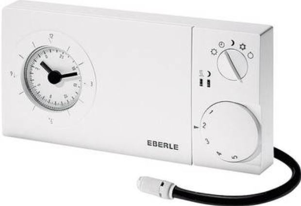
Applications
The easy 3s electronic clock thermostat is designed for room temperature control in conjunction with:
- heating systems, e.g. hot-water heaters, convector heaters or floor heating
- electric convector heaters, ceiling and storage heating
- night-storage heaters
- chillers
- circulation pumps
- burners and boilers
- heat pumps, etc.
- airconditioning applications (cooling only)
Warning!
This unit must not be opened and installed except by authorized persons and in compliance with the circuit diagram provided inside the cover. It is mandatory in all work on the unit to observe the current safety regulations.
In order to classify for protection class II it is necessary to take adequate installation measures.
This separately mounted unit is designed for temperature control exclusively in dry and closed rooms with standard environments. The unit features radio-interference suppression in compliance with VDE 0875 T.14 and EN 55014, respectively, and works according to operating principle 1 C (EN 60730).
Features
- very simple operation
- comfort and setback temperature adjustable
- 5 operating modes (by rotary switch) for:
➩ permanent comfort temperature (5…30°C)
➩ permanent setback temperature (5…30°C)
➩ clock mode (automatic)
➩ frost protection (5°C fixed)
➩ OFF - Indicator lamps for:
➩ heat demand
➩ setback mode - available with daily or weekly timer
- control by phone remote switch possible
- output signal PWM or ON/OFF regulation (adjustable via jumper)
- relay output, 1 x changeover contact
- remote sensor optional
- emergency operation at sensor failure
- hinged cover
- new design 2000
Function description
The clock thermostat is designed to control the room temperature. In the automatic mode, a changeover is effected between comfort and setback mode by the built-in timer. The optionally remote sensor can be used instead of a built-in sensor.
In setback mode, the green indicator lamp lights up. If the room temperature drops below the set value, heating will start, and the red indicator lamp will light up.
Indicator lamps
- Red indicates when the controller demands heat,
- Green indicates when setback mode is activated.
- Red flashing for failure. Operating voltage to be switched OFF and ON again.
Controller heat demand at PWM
If the room temperature drops below the set value, the heating mode will start. The controller output is in the form of pulses of varying lengths (PWM). The length of the pulses depends on the difference between the set and the actual room temperature.
The sum of pulse and pause times can be selected with J4 (between 10 or 25 min.).
If there are large temperature differences, the controller will switch ON or OFF permanently, e.g. when changing over to temperature setback mode. PWM should only be used for current ≤ 10A.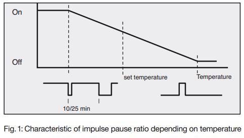
Cycle time setting
For inert applications (e.g. burners) we recommend a long cycle time.
For quick applications (e.g. electric direct heaters) we recommend the short cycle time.
| Plug-in jumper J4
(right side of board) |
Time |
| Double-pole jumper connection | 25 min
(as-delivered condition) |
| Single-pole jumper connection | 10 min |
Heat demand of the controller at ON/OFF regulation
When room temperature drops below set temperature the output will be switched on, whereas it will be switched off, when set value is exceeded.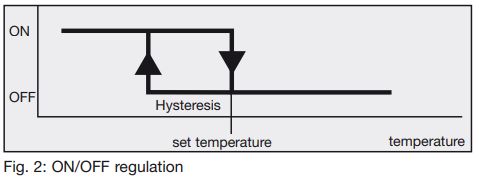
| Plug-in jumper J3
(right side of board) |
Regulation |
| Double-pole jumper connection | ON/OFF |
| Single-pole jumper connection | PWM
(as delivered condition) |
Phone remote switch (only available at special variants)
Via an external phone switching device the controller can be put into mode of comfort or setback temperature. As long as contact (terminal 19) is closed, the comfort temperature
will be “used“. This function ist activated in the modes automatic,
 setback temperature permanent and
 Frostprotection.
Installation
The controller should be arranged in a place within the room which:
- is easily accessible for operation
- is free from curtains, cupboards, shelves, etc.
- enables free air circulation
- is free from direct sun radiation
- is free from draughts (e.g. opening of windows and doors)
- is not affected directly by the source of heat
- is not located on an external wall
- is located approx. 1,5 m above floor level
Mounting directly on conduit box or with adapter frame ARA easy.
Electric connection
Warning! Disconnect electric circuit from supply.
Proceed as follows:
- pull off temperature setting knob
- push retaining hook outwards using screwdriver
- remove housing cover
- make connection in compliance with wiring diagram (see housing cover).
- watch notes
Remote sensor
Having connected the remote sensor, the integral sensing component will be switched off automatically.
The sensor cable is extendable up to a length of max. 50 m. Please use a two-core 230 V cable with a cross section of 1.5 mm2.
The sensor cable (F 193 720) should be installed into a protection tube (pocket). This facilitates later replacement. In case of failure (break or short-circuit) the controller switches into emergency operation:
- at PWM: 30% heating capacitiy
- at ON/OFF: Relay OFF
Warning! Sensor cables carry operating voltage.
Technical data
- Temperature setting range:
comfort temperature 5…30°C
setback temperature 5…30°C
frost protection approx. 5°C fixed - Regulation proportional controller (due to PWM quasi-continuous, see Fig.1)
- Cycle period adjustable 10 or 25 min. (sum of PWM ON and OFF times)
- Proportional band 1,5 K
- Hysteresis ~0,5 K, ≤ 10 A see Fig. 2
~0,5K at 16 A and use with remote sensor
~2,5 K, at 16 A without remote sensor - ON/OFF regulation adjustable via jumper
- Output relay, 1 volt-free* changeover contact
- Switching current 10mA…16 A cos ϕ = 1
max. 4 A cos ϕ = 0,6
max. 10 electro-thermal actuators - Switching voltage 24…250 V AC
- Mode selector switch comfort / automatic / setback / frost protection / OFF
- Phone remote switch Input for 230 V AC (via an external (as variant) phone switching device)
- Indicator lamp: red controller demands heat green setback mode
- Temperature sensor: internal
- Remote sensor type F 190 021 (wall mounting) type F 193 720 length 4m both extendable up to 50m
Sensor Characteristics
42 kΩ at 20°C
26 kΩ at 30°C - Range limitation inside setting knob
Clock:
- accuracy < 10 min./year
- switching time setting every 15 min. with daily timer every hour with weekly timer
- Power reserve approx. 100 h
- Protection class of housingIP 30
- Degree of protection II (see Warning 1)
- Ambient temperature –10…40°C, without condensation
- Storage temperature –25…65°C
- Dimensions 160 x 80 x 36 mm
- Weight approx. 220 g
Note: The volt-free contact of this mains-operated unit does not ensure the requirement for the use of safety extra-low voltage (SELV).
For units with 230 V supply voltage
- Type easy 3st with daily timer easy 3sw with weekly timer
- Article-Nr. easy 3st 517 2701 51 100 easy 3sw 517 2702 51 100
- Operating voltage 195…253 V AC 50/60 Hz
- Power consumption < 1,5 W
For units with low voltage output
- Type easy 3st 1mA with daily timer easy 3sw 1mA with weekly timer
- Article No. easy 3st 1mA 517 2711 51 100 easy 3sw 1mA 517 2712 51 100
- Operating voltage 195…253V AC 50/60Hz
- Switching current >1mA, >1V or max. 10(4) A AC
- Power consumption < 1,5 W
Wiring diagram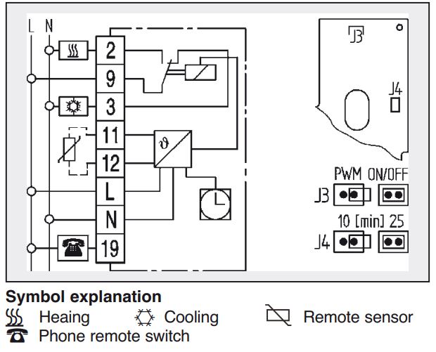
Note
For heating applications
- connect n/c actuators to terminal 2.
- connect n/o actuators to terminal 3.
For cooling applications
- connect n/c actuators to terminal 3
- connect n/o actuators to terminal 2
- To use the red lamp as an indicator for “cooling ON”, connect n/o actuators to terminal 2
- When the mode selector switch is in OFF position n/c and n/o actuators will be closed logically.
Operation
Temperature setting
- Comfort temperature (daytime temperature) is set by means of externally visible seting knob (1)
- Setback temperature (night temperature) is set by means of adjustment knob (2) beneath cover.
Time setting - by putting one finger on dial (3) and turning in any direction, you can set the time.
- Arrow (4) points to the selected time.
Switching time setting - Bring movable tappets (5) into required position using a pointed object.
Outer ring = comfort temperature
Inner ring = setback temperature - Mode selector switch (6) – externally
 Comfort temperature, permanent
Automatic mode, time-controlled changeover between comfort and setback temperature
Setback temperature, permanent
Frost protection, permanent (5°C)
 OFF, there is no control activity. The controller itself is not disconnected from operating voltage.
Batteries
In compliance with the EU Directive 2006/66/EC, the button cell battery located on the printed circuit board inside this product can be removed at the end of the product life, by professional personnel only.
REFERENCE:
DOWNLOAD MANUALS:
Eberle easy 3s Electronic Clock Thermostat Operation Instructions
Eberle Easy 3s Electronic Clock Thermostat Operation Instructions