Drayton Wiser thermostat kit 1

Introduction
Welcome!
Save this guide for future reference. If you are replacing an existing controller/programmer and don’t need to make any wiring changes that’s great news. All you need to do is remove the old product and fit your new Wiser Heat HubR to the existing wallplate. If you are fitting a new system or require re-wiring please contact an installer. If you are fitting a new system or require re-wiring please contact an installer.
IMPORTANT
- Do not attempt to install this product if you are not familiar with how to install mains-powered electrical appliances.
- Always switch off the mains before removing a controller and never fit it to a live wallplate.
Step 1
Mounting the wallplate

Step 1 Continued…
Option 1: Fitting a new wallplate
The ideal location should have reasonable lighting, good access, no condensation, no extremes of temperature, and a supporting surface that fully covers the back of the unit. Position with 70mm clearance to the right, 25mm above, and sufficient room to access the securing screws underneath. Fix, with terminals at the top, either direct to a flat wall using wall plugs and No. 6 x 1” (25mm) woodscrews, or on a flush mounting single conduit box type UA1 (BS4662) using M3.5 x 14 bolts. Now fit the Wiser Heat HubR onto the wallplate and tighten the securing screws. Check the 3A fuse, and switch on the mains.
Option 2: Using an existing industry standard wallplate
Loosen the securing screws on the old controller/ programmer and unplug it. Check that there is 70mm clearance to the right of the wallplate and 25mm above it. Check the wiring diagram for your product model to compare terminals and, if necessary, change the wiring of the wallplate to suit. Now fit the Wiser Heat HubR onto the wallplate and tighten the securing screws. Check the 3A fuse, and switch on the mains.
- DO NOT use a surface mounting box as the wallplate is not designed for this purpose.
- Note: Ensure the Heat HubR is installed in a position with WiFi coverage.
Step 2a: Wiring – wallplate
Make sure the mains input has a 3 amp fuse.
CAUTION! Before installation, make sure the mains supply is switched off!

One channel only: Note that the output contacts are voltage-free, so power needs to be put onto Terminal 1 either by linking from Terminal L or from a separate supply with a 3A fuse.
Note: If there is an existing wired thermostat connected via the wallplate, this must be disconnected, i.e. remove the thermostat wires from the wallplate.
Three channels only: Make a note of which circuit is connected to CH1 and CH3 respectively as this information is needed later, during commissioning, when room thermostats are added to the system.
Note: After wiring, fit the Wiser Heat HubR onto the wallplate and tighten the securing screws. Check the 3A fuse and switch on the mains.
Step 2b:
Wiring – boiler with OpenTherm interface
If your boiler supports OpenTherm, please follow the instructions under this step.
Existing OpenTherm installation
- Remove the OpenTherm cables from the existing controller or thermostat.
- Remove the OpenTherm module from the rear of the Wiser Heat HubR.
- Wire in the OpenTherm cables into the OpenTherm module. It does not matter which way the cables are wired.
- Replace the OpenTherm module with the Heat HubR.
- Wire L & N on the wallplate from a separate supply with a 3A fuse.
- Mount the HubR on the wallplate.
Re-wiring to OpenTherm from the standard installation
Any motorized valves need to be disconnected and set to open. Then follow steps 2-5 above to wire in the OpenTherm.
Important
For compatibility with combi boilers and conventional boilers with hot water cylinders please consult the digital user guide found on wiser.draytoncontrols.co.uk

Step 3: Testing the system
Heating and Hot Water buttons

Pressing & holding the Hot Water button for >3s will turn on the Hot Water for 1 hour. In this state, the hot water will be regulated by a cylinder thermostat or
the boiler. When the Hot Water override is active, the Hot Water LED will flash green. To turn off the override press the Hot Water button again. This will put the hot water back under system control. Depending on the system settings the hot water may stay on which will be indicated by a solid green LED. Tip: This feature can be used to ‘test’ an installation prior to adding any devices.
Note: The heating and hot water button override states are not shown in the app. These act as a fallback state in the event that other controls are unavailable.
Heating override button
Pressing & holding the Heating button for >3s will turn on the heating for 2 hours. In this state, the boiler will self-regulate its temperature. When the Heating override is active, the Heating LED will flash green. To turn off the override press the Heating button again. This will put the heating back under system control. Depending on the system settings the heating may stay on which will be indicated by a solid green LED.
Connection Charts
Always switch off the mains before removing the Wiser Heat HubR – and never fit it to a live wallplate! Make the wiring connections, as shown in the connection charts, for the appropriate system. For surface wiring, snap out the cable entry strip on the bottom edge of the wall plate. The Wiser Heat HubR is double-insulated and needs no earth connection, but an earthing continuity (loop) terminal is provided for convenience.
Note: If there is an existing wired thermostat, it must be completely disconnected, i.e. remove the thermostat wires from the wiring center – a link must be inserted between the terminals where the thermostat is common and call for heat wires located in the wiring center.
Arrowed numbers relate to the junction box.
Consult the boiler handbook for details of the pump overrun wiring.
After wiring, clip on the unit and tighten the securing screws. Check the mains input has a 3A fuse, and switch on the mains.
- LS = Live Supply
- LR = Live Return

Connection Charts
Always switch off the mains before removing the Wiser Heat HubR – and never fit it to a live wallplate! Make the wiring connections, as shown in the connection charts, for the appropriate system. For surface wiring, snap out the cable entry strip on the the bottom edge of the wall plate. The Wiser Heat HubR is double-insulated and needs no earth connection, but an earthing continuity (loop) terminal is provided for convenience.
Note: If there is an existing wired thermostat, it must be completely disconnected, i.e. remove the thermostat wires from the wiring centre – a link must be inserted between the terminals where the thermostat common and call for heat wires are located in the wiring centre.
Arrowed numbers relate to the junction box. Consult boiler handbook for details of pump overrun wiring.
After wiring, clip on the unit and tighten the securing screws. Check the mains input has a 3A fuse, and switch on the mains.
- LS = Live Supply
- LR = Live Return

Step 4: Download the app
Adding Room Thermostats and Radiator Thermostats In order to continue the installation of your Wiser Room Thermostat(s) or Wiser Radiator Thermostat(s)
you will now need to download the Wiser Heat app for your smartphone. The Wiser Heat app is available from the App Store or Google Play. Please ensure you
download the app named ‘Wiser Heat’.

The app guides you through the setup and installation process which connects your Room Thermostat(s) and Radiator Thermostats with the Wiser Heat HubR
and thereafter connects the Heat HubR to the internet. Please note that when connecting the Heat HubR to the internet you will be prompted for your e-mail and address. A verification e-mail will be sent to you to confirm your e-mail address before the app can be used to control your Wiser system. If the email does
not arrive please check your junk email.

Once the Room Thermostat (and Radiator Thermostats) have been added to the system and you have confirmed your email, Wiser is ready to control your heating and hot water. To control your Wiser system from additional smartphones simply download and install the app and login using the same e-mail address and password.
Wiser Room Thermostat
Mounting Options C
are should be taken to mount the Room Thermostat in a position which is not subject to direct sunlight or draughts. Preferably it should be mounted on an inside wall about 1.2m (4ft) above the floor in a position where it can respond to room temperature but away from the direct influence of radiators or other appliances giving off heat.

Once the best position has been identified, the Wiser Room Thermostat should be fixed to the wall using the wall bracket as shown. It can also be positioned
using the table stand included. It has to be positioned in a location where it will be able to control the room temperature.

Mounting Options continued…
It is important to note where to put the Room Thermostat(s) and Radiator Thermostat(s). Please see below for a quick guide.
Thermostat Kits 1, 2 & 3:
Place 1 Room Thermostat in each zone For optimum comfort and savings, each radiator in your home should be fitted with a Wiser Radiator Thermostat. These can be purchased and installed individually.
Signal Strength
It is recommended that the signal strength icon on the Room Thermostat shows two or three bars to ensure communication is maintained with the Wiser
Heat HubR. If this cannot be achieved for any of the preferred locations, a range extender is needed. These are available through Drayton, please call Customer Services on the number indicated on the front page of this guide. If the Room Thermostat has no signal this will be indicated by an LED on the Room Thermostat flashing red 4 times periodically.
Boost
Feeling a bit cool?
- Go to the Room Thermostat and touch any button to wake it up.
- Touch the centre button again to activate boost
- 1st touch = 30 minutes,
- 2nd touch = 1 hour
- 3rd touch = 2 hours,
- 4th touch = 3 hours
- 5th touch = Cancel
- Shortly after the room will start to warm.
Note: A boost will increase the setpoint to 2˚C above the mbient temperature for the time period selected. You can still adjust the setpoint when boosted.
Wiser Radiator Thermostat
Multi-zone System
Economy use
- Place the Room Thermostat in a room which is heated most of the time, typically the lounge/ hallway.
- place the Radiator Thermostat(s) in rooms that are not used all day such as bedrooms.
- The room with Radiator Thermostats can now be scheduled separately to avoid heating them with the rest of the rooms. For optimum comfort and savings, each radiator in your home should be fitted with a Wiser Radiator Thermostat. These can be purchased and installed individuall
Mounting Options

As radiator valve bodies are not all the same, Wiser Radiator Thermostats come with two valve adapters; M30x1.5mm and Danfoss RA. First remove the old thermostatic head from the valve body. Water should not leak from the valve whilst doing this. (Refer to the manufacturer’s instructions if needed.) You are now ready to install your new Wiser Radiator Thermostat.
Note: Turning the head to the highest position/ number will simplify de-installation Once you have set up your Radiator Thermostat(s) through the app, you will be asked to select and fit the required adapter. When fitting and tightening the adapter to the Radiator Thermostat, please make sure that the O-ring is firmly seated above the thread as to avoid damaging the O-ring. Tighten by hand only.
Fitting M30x1.5mm

Place the small black plastic adapter serrated face down onto the valve. Position the metal ring nut over the black plastic adapter and screw it onto the valve. Now screw the Radiator Thermostat onto the black plastic adapter until tight. If the Radiator Thermostat is not facing the right direction, slacken the metal
ring nut and rotate the Radiator Thermostat as required and re-tighten the metal ring nut. Thermostatic head calibration Upon fitting of the relevant valve adapter, twist th cap of the Radiator Thermostat in the – direction for 2 seconds until the right LED shows a solid blue.
Fitting the Danfoss RA
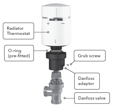
Slide the larger black plastic adapter small end first over the valve. Make sure that the hole containing the grub screw is facing away from you. This way, once its mounted, the markings of the Radiator Thermostat will be in the required position. Use an appropriate size Allen key to tighten the grub screw. Now screw
the Radiator Thermostat onto the larger black plastic adapter until tight.
Thermostatic head calibration
Upon fitting of the relevant valve adapter, twist the cap of the Radiator Thermostat in the – direction for 2 seconds until the right LED shows a solid blue.
IMPORTANT
To limit temperature in other rooms use existing thermostatic radiator heads. We suggest regulating these according to manufacturer’s documentation to provide either economy or comfort use.
LED Behaviour for Radiator Thermostat and Heat HubR
Radiator Thermostat – Calibration
| State User Interaction | Left LED | Centre LED | Right LED | Behaviour | |
| Start up | Insert the batteries | Red | Green | Blue | Single quick flash |
| Opening the valve | Automatic upon inserting batteries
OR Twist and hold the cap in + direction for 8 seconds (For changing batteries) |
Red | Solid until the valve is open | ||
| Ready to install on the valve | The Radiator Thermostat is ready to install when the valve is fully Open (see above) | Red | Orange (not joined)
OR Green (joined) |
Blue | Red/Blue LED Flash for up to
5 minutes – the centre LED is solid |
| Closing the valve | Twist and hold the cap in the – direction for 2 seconds | Blue | Solid until the valve is closed | ||
| Joining | Twist and hold the cap in the + direction for 3 seconds | Green | Pulses for up to 2 minutes | ||
| Join success | N/A | Green | Solid for 5 seconds | ||
| Joining failed | If no network is found after 2 minutes | Orange | Flash for 5 seconds | ||
Radiator Thermostat – Normal Use
| State User Interaction | Left LED | Centre LED | Right LED | Duration | |
| Boost up | Twist the cap in the + direction | Red | Solid for 5 seconds | ||
| Boost down | Twist the cap in the – direction | Blue | Solid for 5 seconds | ||
Radiator Thermostat – Error States
| State User Interaction | Left LED | Centre LED | Right LED | Duration | |
| Low battery | N/A | Red | Solid for 1 second (Repeated) | ||
| Critical battery | N/A | Red | Fast flash for 5 seconds (Repeated) | ||
| No network | Twist the cap in the + or – direction to start a boost | Orange | Solid with fade-out after 2 seconds (In this event the Radiator Thermostat has not joined the Wiser system and must either join the Heat HubR or be re-installed) | ||
Heat HubR – Setup
| State Button Press | LED | Description | |
| Normal | Solid Green | Indicates that the Heat HubR is powered On and operating as normal | |
| Setup | Single press | Flashing Green | This is the Setup state, in this mode it is possible to connect directly to the Heat HubR via WiFi and make changes to the system |
| Adding a Device | Press and hold for >2s (or initiate from the App) | Cycle between Green/Orange | Indicates that the Heat HubR is open to new devices joining the network |
| WiFi Error | Flashing Red | The Heat HubR is unable to connect to your WiFi Network, check that your WiFi router is powered on and connected to the internet. If you’ve changed you WiFi credentials (e.g. password), or if you have a new router you will need to connect to your Heat HubR in Setup mode and update your WiFi network details. | |
| Cloud Connection Lost | Solid Red | The Heat HubR is currently unable to contact the Wiser Cloud service. You will still be able to use the app at home when connected to the same WiFi network as your Heat HubR | |
Adding a Range Extender
| Press and Hold the ‘Setup’ button on the Heat HubR for >2s | Heat HubR Setup LED alternating Green/Orange | Indicates that the Heat HubR is ready to pair a range extender. |
How do I know when to change the batteries?
Room Thermostat
For the majority of time you will see three bars indicated for battery life. When the batteries reach 5% capacity two bars will be shown. One bar will be
shown at 2% capacity. At 1% there will be no bars and the battery icon will be red. At this point the batteries are exhausted and must be replaced or the Room
Thermostat will cease to function. When a Room Thermostat has low batteries this will be indicated by an LED flashing red once

- Remove the battery covers as shown below.
- Replace the exhausted batteries with 2 x 1.5V IEC LR6 (AA) alkaline batteries ensuring correct orientation. Do not use rechargeable batteries.
- Replace the battery covers pressing fully home.

Radiator Thermostat
When the batteries are low (2%) the centre LED will flash red once every hour. For critical batteries (1%) the centre LED will flash red every minute until the
batteries are replaced or exhausted. Low or critical battery level will also be shown by flashing the centre LED red when the cap is twisted. Battery life indication is shown in the app under “Rooms and Devices”. Low or critical battery level will also be notified in the app.
- Remove the battery cover as shown. You may need to unscrew the Radiator Thermostat slightly to access the battery cover.
- Replace the exhausted batteries with 2 x 1.5V IEC LR6 (AA) alkaline batteries ensuring correct orientation. Do not use rechargeable batteries.
- Replace the battery cover.
- Screw on the Radiator Thermostat if loosened or removed.
- Twist the cap in the minus direction for 2 seconds immediately calibrate the Radiator Thermostat. If this step is not done then the Radiator Thermostat
will not function.
Battery Handling
Batteries, rechargeable or not, should not be disposed of into ordinary household waste. Instead, they must be recycled properly to protect the environment and cut down the waste of precious resources. Your local waste management authority can supply details concerning the proper disposal of batteries. In compliance with the EC Directive 2006/66/EC, the button cell battery located on the printed circuit board inside the Wiser Heat HubR, can be removed at the end of the product life, by professional personnel only.
Removing devices from a system
Devices can be removed from the Wiser system either via the Wiser Heat app or the Room Thermostat/Radiator Thermostat.
- Via the app, login to the system and navigate to ‘Rooms and Devices’. Locate the device you want to remove and select ‘Remove Device’.
- Via the Room Thermostat, remove the batteries and re-insert them. Once the splash screen is displayed, press and hold the + and – buttons on the Room Thermostat for 20 seconds until ‘Join a network’ is displayed. The Room Thermostat has now been removed from the Wiser system.
- Via the Radiator Thermostat, twist and hold the cap of the Radiator Thermostat in the – direction until the centre LED flashes red 8 times. Upon releasing the Radiator Thermostat cap all LEDs will flash once. If successful the valve will automatically open and the left and right LEDs will flash red and blue respectively and the centre LED will show a solid orange (for up to 5 minutes). The Radiator Thermostat has been removed from the Wiser system once the two LEDs start to flash red and blue.
- It is also possible to return the Heat HubR to factory settings and thereby removing all devices from the system instantly. This is done by pressing and holding the Setup button on the Heat HubR for more than 20 seconds. The setup LED will first go out, then light up orange followed by red. When the LED is red release the button. After a few seconds the LED goes back to solid green. The Heat HubR has now returned to factory settings and all devices have been removed. Note that to re-use the devices you will also need to perform a device reset on all individual products in accordance with the instructions in this section.
ErP Rating
| ErP Class with Modulating boiler | ErP rating | ErP Class with on/off boiler | ErP rating | |
| Wiser Thermostat Kit 1 | VI | 4% | VII | 3.5% |
| Wiser Thermostat Kit 2 | VI | 4% | VII | 3.5% |
| Wiser Thermostat Kit 3 | VI | 4% | VII | 3.5% |
| Wiser Multi-zoning Kit 1 | VIII | 5% | VII | 3.5% |
| Wiser Multi-zoning Kit 2 | VIII | 5% | VII | 3.5% |
Technical Data
| Wiser Heat HubR | Wiser Room Thermostat | Wiser Radiator Thermostat | |
| Dimensions | 93mm(w), 148mm(h), 31mm(d) | 76mm(w), 76mm(h), 25mm(d) | 93mm(h), 51mm(dia) |
| Power Supply | 230V a.c. ±10% 50Hz | 2×1.5V IEC LR6 (AA) alkaline batteries | |
| Switch Rating | 2(1)A 230V a.c. each switch Total load must not exceed 2.5A | N/A | |
| Wiring | Fixed wiring only, to comply with current IET regulations (BS7671) | No wiring required | |
| Battery Life | N/A | 2 years typical | |
| Interfaces | User: Push Button/LED; I/O: Mains Relays (1-3), Digital Boiler Interface | User: TFT display, touch buttons; I/O: None | User: Twist Cap, LED; I/O: None |
| Operating Temperature | 0°C to 45°C | ||
| Storage Temperature | -10°C to 55°C | ||
| Maximum Mounting Surface Temperature | N/A | 93°C | |
| Maximum Water Temperature | N/A | 73°C continuous and 110°C max | |
| Ingress Protection | IP 30 | IP 20 | IP 30 |
| Ambient Humidity (non-condensing) | Operating 25% to 90%, Storage 15% to 95% | ||
| Set-point Range | 5°C to 30°C | ||
| Control Accuracy | <0.6°C at 4°C/hour (with Room Thermostat) | N/A | |
| <0.8°C at 4°C/hour (with Radiator Thermostat) | N/A | ||
| Timing Resolution | 1 minute | ||
| Temperature Resolution | 0.5°C | ||
| Ball Pressure Test Temperature | 92°C | 75°C | |
| Pollution Degree | 2 | ||
| Software Class | A | ||
| Without Mains Power | Display: LEDs off; Time: always kept; Program times: always preserved | N/A | |
| Rated Impulse Voltage | 2.5kV | N/A | |
| Radio Technology/Frequency | 2.4GHz (Bi-directional, Mesh) | ||
| Radio Signal Range | 30m Free Space | ||
| Maximum Radio-Frequency Power Transmitted | 17dBm (50mW) | +10dBm (10mW) | +10dBm (10mW) |
| Mounting | Industry standard wall plate | Wall bracket or desk stand | Radiator Valve |
| Relevant Directives | Radio Equipment Directive (RED) 2014/53/EU, Batteries Directive 2006/66/EC, RoHS Directive 2011/65/EU | ||
| Applied Standards | EN60730-1; EN60730-2-7; EN60730-2-9, EN 300 328 | ||
Hereby, Schneider Electric Controls UK Ltd, declares that these products are in compliance with the essential requirements and other relevant provisions of RED 2014/53/EU. Declaration of Conformity can be downloaded from: www.draytoncontrols.co.uk
- Schneider Electric Controls UK Ltd
- 401 Southway Drive
- Plymouth
- PL6 6QT
- United Kingdom
REFERENCE:
Download Manual: Drayton Wiser thermostat kit 1 Installation Guide
