
Drayton LP10RF & DIGISTAT+2RF

Radiofrequency-controlled programmable room thermostat with domestic hot water programmer. For GREENSTAR CDi, GREENSTAR JUNIOR, and GREENSTAR Si MODELS also GREENSTAR SYSTEM and GREENSTAR CDi SYSTEM MODEL(only when used with the optional integral diverter).
Support
- 401 Southway Drive
- Plymouth
- PL6 6QT
- United Kingdom
- Technical: +44(0)333 7000 622
- [email protected]
- www.draytoncontrols.co.uk
- DraytonHeating /DraytonControls
PLEASE READ THESE INSTRUCTIONS CAREFULLY BEFORE STARTING
These instructions are applicable to the Drayton model(s) stated on the front cover of this manual only and must not be used with any other make or model.
These instructions apply in the UK only and should be followed except for any statutory obligation. If you are in any doubt contact the Drayton technical helpline. This accessory must be fitted by a competent person. Failure to comply could lead to prosecution. Leave these instructions with the user or at the appliance.
Symbols
![]() Domestic Hot Water
Domestic Hot Water
![]() Radio Frequency (RF) Transmitter
Radio Frequency (RF) Transmitter
Abbreviations
- CH = Central Heating
- DHW = Domestic Hot Water
- RF = Radio Frequency
- DLS = Daylight Saving
- BST = British Summer Time
- GMT = Greenwich Mean Time
- C = Celsius (Centigrade)
- IP = Ingress Protection
- V = Volt
- m = metre
- mA = milliAmpere
Definitions (DLS/BST)
Summertime begins Last Sunday in March at 1:00 am GMT (Clocks are put forward by 1 hour) Summertime ends: Last Sunday in October at 2:00 am BST (Clocks are put back by 1 hour)
 Protect your environment
Proper battery recycling
Electronic devices and batteries, rechargeable or not, should not be disposed of into ordinary household waste. Instead, they must be recycled properly to protect the environment and cut down on the waste of precious resources. Your local waste management authority can supply details concerning the proper disposal of batteries.
Technical Data
| Digistat +2RF Transmitter Thermostat | LP10RF Receiver | |
| Dimensions | 137mm x 96.5mm x 31.3mm | — |
| Power supply | 2xAA 1.5V alkaline batteries | 24Vd.c. less than 65mA |
| Radio frequency | 433 MHz | 433 MHz |
| Radio signal range | 30m typically. The range may be affected by the composition / density and number of walls between the Digistat+2RF and LP10RF. | |
| Temperature range | 5°C to 32°C | — |
| Ambient operating temperature | 0°C to +40°C | 0°C to +50°C |
| Humidity operating range | 25 – 90% non condensing up to 45°C | 30 – 95% non condensing up to 45°C |
| Class of operation | — | II |
| Degrees of protection | IP30 | IP24 |
| Control Accuracy | +0.5°C @ 20°C | Better than ±1 second per day @ 25°C |
| Battery life (with alkaline batteries) | approx. 2 years | N/A |
| Battery back up time and date | 10 years min. | 10 years min. |
| Shortest switching period | 1 minute | 1 minute |
| Hot water pre-heat settings | — | 3 ON / 3 OFF |
| Central heating settings | 6 per day | — |
| Energy Class | IV = 2% (Acc. EU 811/2013, 812/2013, 813/2013, 814/2013) | |
| Pollution Class | 2 | 2 |
| Software Class | A | A |
| Ball pressure test | 90°C | 90°C |
| Software version | 6712056 | — |
| Max. radiated power | +7.5 dBM (5.6mW) | — |
Relevant EC Directives
- 2014/53/EU RED Directive
- 2006/66/EC Battery Directive
- 2011/65/EU RoHS Directive
Applied Standards
- EN60730-1; EN60730-2-7; EN60730-2-9
- EN 300 220-2; EN 301 489-3
Pack Contents
- LP10RF Programmer / RF receiver
- Digistat+2RF transmitter
- Screws (x2)
- Wall Plugs (x2)
- Instructions
Batteries (x2) AA Alkaline
Hereby, Schneider Electric Controls UK Limited, declares that this programmable room thermostat is in compliance with the essential requirements and other provisions of RED Directive 2014/53/EU. Declaration of conformity can be downloaded at: www.draytoncontrols.co.uk.
LP10RF Installation
DANGER
230 volts do not touch the electrical components or circuits.
CAUTION
Isolate the mains electricity supply before starting any work and observe all relevant safety precautions. Observe electro-static discharge precautions: do not touch the PCB circuit.

NOTE
This accessory must be fitted by a competent person. Failure to comply could lead to prosecution.
- Remove the boiler outer casing and control panel fascia to gain access to the boiler control panel.
- Release the securing screws.
- Pull the cover panel up to remove it.
- Grip the tab and pull upwards to disengage clips, and pull forward to remove the blanking plate or existing programmer.
- Align the connector plug pins into the socket on the PCB and push fully home.
- Feed the ribbon cable into the recess.
- Align the programmer and locate the clips, push into the slots then down to secure.
- Locate the cover panel in place and secure it with the screw.
- Replace the fascia cover and outer casing before switching on the electrical supply and boiler.

Wireless Commissioning & Signal Strength
NOTE
Before fixing the DIGISTAT+2RF to the wall it is recommended to first check the signal strength from that location. Wireless commissioning: after initial start-up, the colon, CH, and antenna symbols should be flashing on the LP10RF display.

Follow either ![]() to below
to below
- Press & hold the set? button for 5s and Learn and OFF will be displayed. OR
- Press the set? button 4 times.
- Press the OK button once.
- Press the set? button 4 times; Learn and OFF will be displayed.

- Press the + button so the display shows ON and a flashing antenna symbol. The learning mode is now ready to receive a signal from the transmitter during the next two minutes.

- Take the Digistat+2RF unit and stand near the boiler.
- Remove the battery cover and fit the batteries

- The symbols on the LP10RF will stop flashing and the display will show ‘SSI, Antenna, and ON’.
NOTE
If you want to exit the home screen now without checking the signal strength then please press the ‘OK/-’ button, then the ‘set?’ button. Alternatively, you can leave for 2mins and the LP10RF will automatically return to the home screen. See p.6 for how to mount the Digistat to the wall.
- Press ‘SET’ on the LP10RF and the display will show ‘SSI and Antenna’.
- After a few seconds, the display will show ‘- – -’. Remove the batteries from the Digistat+2RF, and press and hold the ‘+’ button whilst refitting the batteries, keep the ‘+’ button held and after a few seconds, the display will show ‘rF’ which indicates that the DIGISTAT+2RF is continuously sending a signal to the LP10RF (receiver). The LP10RF display will now show the ‘learned’ transmitter code and the antenna’ as well as the signal strength as indicated by the chevrons on the right-hand side of the display.
- Place the Digistat+2RF in the desired final position and return to the boiler to check the LP10RF display. The ideal Digistat+2RF position will result in the LP10RF display showing 4 chevrons and the LED will be green.
- If the LED is red or no LED is showing and the display indicates 1 or 2 chevrons, the Digistat+2RF will need to be re-positioned until the LED changes to amber or green and 3 or 4 chevrons are indicated on the display
NOTE
If there is no LED and the display on the LP10RF shows ‘- – -’, there is no signal being received at all from the Digistat+2RF. The transmission will resume once the Digistat+2RF is re-positioned in a part of the house where an amber or green LED and 3 or 4 chevrons are achieved. - Once you are happy that, when in the desired location, the Digistat+2RF is sending a good signal to the LP10RF i.e. amber or green and 3 or 4 chevrons, the Digistat+2RF can be fixed to the wall.
NOTE
Continue on the next page to cancel the signal strength mode.
LED indicator shows different colours depending on signal strength (see table below)
| LED Indication | Chevrons | RF Strength |
| Green | 4 | Very strong |
| Amber | 3 | Strong |
| Red | 2 | Weak |
| None | 1 | Very weak |
To cancel signal strength mode
- Remove the batteries from the Digistat+2RF transmitter to cancel the constant transmission.
- After a few seconds, the LP10RF display will show

- Press ‘OK’ on the LP10RF and the display will return to the time with the ‘CH and Antenna’ flashing.

- Re-insert the batteries into the Digistat+2RF and the RF link will be re-established
Positioning the Digistat +2RF room thermostat
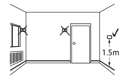
The Digistat is a radio frequency device that is very flexible for positioning as there is no need for hard wiring to the appliance. The device should be mounted in an open area, no closer than 30cm from metal objects, including wall boxes. Mount the Digistat+2RF on a wall that is not subject to direct sunlight or draughts, preferably on an inside wall, 1.5 meters above the floor. The Digistat+2RF must also not be directly influenced by radiators or other appliances giving off heat.
Mounting the Digistat+2RF room thermostat
- Remove the front cover using a flat screwdriver and separate it from the back plate.

- Fix the back plate directly onto the wall using the allocated fixing points and suitable wall plugs and screws.

- Replace the front cover by locating it in position and pushing it fully onto the back cover.

- Remove the battery cover using a coin

- Install the 2 AA batteries provided

- Replace battery cover

Signal Strength
To check the signal strength on previously installed and paired units:
Follow either ![]() below
below
- Press & hold the set? button for 10s and ‘SSI and OFF’ will be displayed.
- Press the set? button 4 times.
- Press the OK button once.
- Press the set? button 5 times; ‘SSI and OFF’ will be displayed.

- Press the ‘+’ button so that the display shows ‘SSI, Antenna, and ON’.

- Press the ‘set’ button so the display shows ‘SSI and Antenna’.

- After a few seconds, the display will show
- Remove the batteries from the Digistat+2RF and wait until the display has faded away.
- Press and hold the ‘+’ button on the Digistat+2RF while re-inserting the batteries and keeping the button depressed until the display shows

LED indicator shows different colors depending on signal strength (see table below)
| LED Indication | Chevrons | RF Strength |
| Green | 4 | Very strong |
| Amber | 3 | Strong |
| Red | 2 | Weak |
| None | 1 | Very weak |
To cancel signal strength mode
- Remove the batteries from the Digistat+2RF to cancel the constant transmission.
- After a few seconds, the LP10RF display will show
- Press ‘OK’ on the LP10RF and the display will return to the time with the ‘CH and Antenna’ flashing.

- Re-insert the batteries into the Digistat+2RF and the RF link will be re-established
Installer Options
If you wish to change any of the Installer Options as shown in the table below, enter the Installer Options Menu from Auto mode by pressing: ![]() and +
and +
simultaneously for 5 seconds.

Pressing![]() and + again for 5 seconds will exit the Menu and return to Auto mode. Once the
and + again for 5 seconds will exit the Menu and return to Auto mode. Once the![]() Installer Options screen has been selected, the buttons allow you to scroll through the Menu (shown below). The + and
Installer Options screen has been selected, the buttons allow you to scroll through the Menu (shown below). The + and ![]() – allow you to change values. Once a value has been changed pressing
– allow you to change values. Once a value has been changed pressing![]() before exiting the Menu will save the new setting. (The below display shows Option 02 OFF).
before exiting the Menu will save the new setting. (The below display shows Option 02 OFF).

| Installer Options | Function | Select Option | Default | |
| 02 | Freeze protection | On | Off | On |
| 04 | Low Set Point °C | 5 | High Limit | 5 |
| 05 | High Set Point °C | Low Limit | 32 | 32 |
| 06 | Delayed Start (Energy saving feature) | On | Off | Off |
| 10 | Valve protection | On | Off | Off |
| 11 | Valve protection time (Mins) | 1 | 5 | 3 |
| 12 | Application type | 0 | 1 | 0 |
| 13 | System Capability | 0 | 1 | 0 |
Option 02 – Freeze Protection
Freeze protection will switch on the heating if the room temperature falls to 5°C and will then control the temperature at 7°C even if the Digistat is in OFF mode. The Freeze Protection default is ON. To switch off the Freeze Protection mode enter the Installer Options Menu (Refer to Installer Options 02) and change to OFF. Press to accept.
Option 04 & 05 – Low and High Limit set points.
The user temperature set points defaults are High 32°C and Low 5°C, to change these limits enter the Installer Options Menu (Refer to Installer Options 04 & 05).
Option 06 – Intelligent Delayed Start (Energy saving feature)
The Intelligent Delayed Start is an energy-saving feature that automatically reduces the warm-up time for the heating system. If enabled, the start time should be set an hour earlier then the time you want the property to reach the set temperature. Intelligent Start will delay that start time, by an amount that it has been calculated based on the actual and set temperature. As the weather becomes milder, the start time is delayed, so that fuel is not wasted bringing the room up to temperature earlier than necessary. The Digistat calculates approximately 10 minutes to raise the temperature by 1°C, up to a maximum of 6°C.
NOTE
Intelligent Delayed Start only applies in Auto mode. Intelligent Delayed Start default is in OFF mode. To switch ON Intelligent Delayed Start enter the Installer Options Menu (see Installer Options 06).
NOTE
The Intelligent Delayed start option is not suitable for underfloor applications. Ensure Installer option 06 is set to OFF before final commissioning for underfloor application.
SPECIAL NOTE
If the Intelligent delayed start feature is enabled, (Off changed to On in Installer option 06), please inform the end user of this feature.

The following special note has been added to the user instruction to explain the adjustment requirement: When the delay period is operating as indicated by the flame symbol flashing, pressing any button returns the Digital to auto mode allowing normal button operation until the next time/ temperature event, when it will resume the delay start mode or follows the Holiday, Manual, Override, or Off modes as selected. Changes to the installer options and pre-set programs must be made with the flame symbol not flashing.
Option 10 – Valve Protection
In some heating systems, there may be a requirement to protect the system by operating it once a day, for a given period. If valve protection is selected the system will be operated for a period as shown in valve protection time (mins). Valve protection time is every day at 10.00 am. The valve protection default is OFF. To enable the valve protection mode enter the Installer Options Menu (Refer to Installer Option 10).
Option 11 – Valve Protection time (mins)
Valve protection time can be set between 1 and 5 minutes (default 3 minutes). To change this once a day on time enters the Installer Options Menu (Refer to Installer Option 11).
Option 12 – Application Type
Digistat+2RF can be used for different applications.
In the installer menu, select:
- 00 = Gas Boiler
- 0 1 = Oil Boiler
Option 13- System Capability
Adjust this setting to suit the heating system capability.
In the installer menu, select:
- 00 = Fast – the house usually reaches setpoint in ‹ 1 hour
- 0 1 = Slow – the house usually reaches setpoint in › 1 hour
Display Error code E1
When the display shows an error code (E1) this indicates a sensor fault and the heating system will remain Off. Please contact your local heating service engineer to replace your Digistat +2RF.
OTHER MANUAL:
Drayton LP10RF & DIGISTAT+2RF User Guide
Drayton LP10RF & DIGISTAT+2RF Installation
Skip to PDF content