
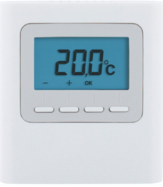
Delta Dore 8000-TA-BUS Zone Thermostat
TECHNICAL CHARACTERISTICS
- Power supply by the bus: 24V
- Bus Input/output: 2 wires
- Class III: insulation
- Surface-mounted or on flush-mounting: box
- Dimensions: 81 x 88 x 21 mm
- Degree of protection: IP 30
- Operating temperature: 0 to +40°C
- Storage temperature: -10 to +70°C
- Installation in an environment with normal: Pollution levels
LOCATION/MOUNTING
Since the temperature measurement sensor is inside the unit, you must install the thermostat flush-mounting box: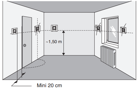
- on an accessible wall at a height of 1.50 m
- away from heat sources (fireplaces, sunlight) and draughts (windows, doors)
IMPORTANT: Do not install the thermostat on a wall in contact with the outdoors or with an unheated room (e.g. garage, etc.)
The sleeve output in the flush-mounting box must be blanked off (with mastic) in order to avoid unwanted air movements that would cause the sensor reading to be inaccurate.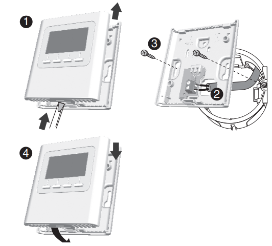
- Separate the unit from its base by pushing the pin using a screwdriver.
- Connect the bus to the terminal on the base
- Mount the base to the flush-mounting box.
- Refit the thermostat back on its base.
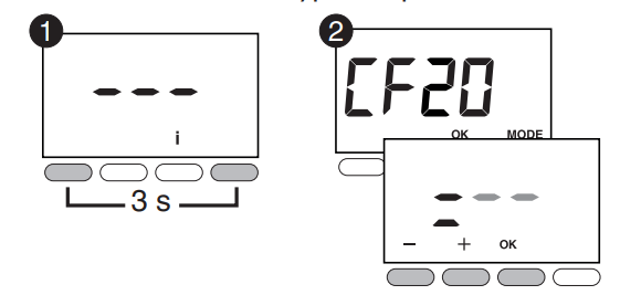
ASSOCIATION OF THE THERMOSTAT WITH THE TECHNICAL UNIT
- Press and hold the 1st and the 4th button for 3 seconds. Release.
- The screen displays CF20.
Press OK then press + and – to select the output with which the room thermostat will be associated.
Confirm with OK. - The screen displays CF21.
Select the transmitter and press OK. - The screen displays CF05.
Select the thermostat type and press OK.
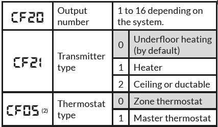
CF05: the Master thermostat enables the centralised use of ON/OFF and HEAT/COOL (at least one Master thermostat is required in an installation without a programmer).
CONFIGURING THE ROOM THERMOSTAT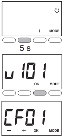
- From the OFF mode. Press and hold the 2nd button from the left for 5 seconds.
Release. - Tap the OK button. Release.
- The screen displays CF01.
- Press + or – to select the menu.
- Press OK to enter the setting mode, then + and – to perform the setting.
|
Temperature management |
On/Off management |
HEAT/ COOL
mode management |
|
| Master thermostat | On the controlled zone |
On all zones |
On all zones |
| Zone thermostat | On the controlled zone | On the controlled zone |
– |
| Correction of the measured
temperature |
+/- 5°C in 0.1°C increments (0°C by default) | ||
|
Temperature displayed in normal mode |
0 | Setting display (default selection) | |
| 1 | Display of the measured temperature. | ||
|
|
Ban on the Cool regulation on the thermal zones of the Room Temperature (if SW2 = ON) | 0 | No ban (default selection) |
| 1 | Ban | ||
| Display the status (ON) of the
associated output |
0 | No (default selection) | |
| 1 | Yes | ||
|
Thermostat type | 0 | Zone thermostat (default selection) |
| 1 | Master thermostat | ||
- CF03 only appears in Heat/Cool production mode (SW2=ON, refer to the technical unit manual) and for underfloor heating (CF21 =0) or for ceiling/ductable (CF21 = 2).
- CF05: the Master thermostat enables the centralised use of ON/OFF and HEAT/COOL (at least one Master thermostat is required in an installation without a programmer).
| Activation of the window/door magnetic contact function (the room thermostat switches to Frost Protection mode if the window/door magnetic contact is activated). | 0 | Not activated | |
|
1 |
Activated (default selection) |
||
| ‘Presence detection’ function
(the thermostat lowers its setting in the event that no presence is detected). |
0 | Not activated | |
| 1 | Activated (default selection) | ||
|
Standby mode |
0 | Display off after a 10 seconds time-out
period |
|
| 1 | Display illuminated continuously (default
selection) |
||
|
Backlighting |
0 | Deactivated | |
| 1 | When activated, it goes out after a 5-second time-out period (default) | ||
| Output number | 1 to 16 depending on the system. ‘–‘ is displayed if none are allocated. | ||
|
Transmitter type |
0 | Underfloor heating (by default) | |
| 1 | Heater | ||
| 2 | Ceiling or ductable | ||
| Heating percentage limitation | From 10 to 100% in increments of 10 (100%= No limitation, by default). | ||
INITIALISATION
DELETING ALL THE ASSOCIATION BUS WITH THE TECHNICAL UNIT
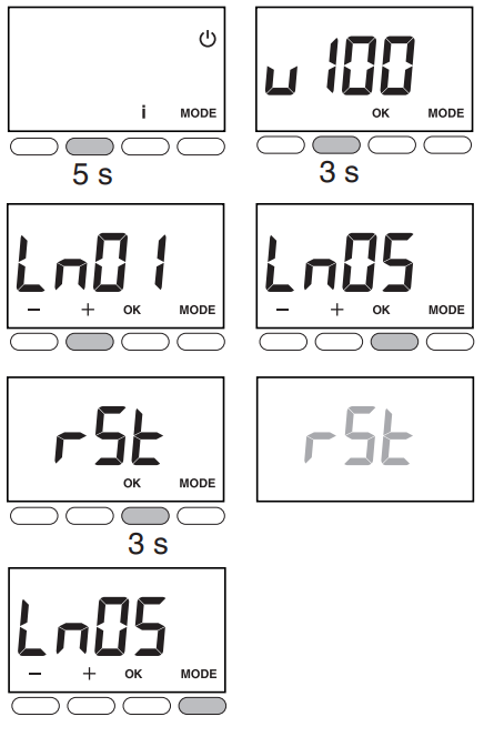
- From the OFF mode.
Press and hold the 2nd button from the left for 5 seconds. Release. - Press and hold the 2nd button from the left again for 3 seconds. Release.
- The screen displays Ln01. Press + to display Ln05.
- Press OK. The screen displays rSt.. Press and hold OK for 3 seconds. rSt flashes for 2 seconds.
Release. - Press MODE to exit.
DELETING THE ASSOCIATION OF THE THERMOSTAT WITH THE TECHNICAL UNIT
Press OK to open the setting, then press + and – to select «= –». Confirm with OK.

INITIALISING THE ROOM THERMOSTAT SETTINGS
This menu restores the system to factory settings.
- From the OFF mode. Simultaneously press the 1st and 3rd buttons from the left for 10 seconds. The screen displays rSt1. Release.
- Press and hold OK for 3 seconds until the rSt display flashes. Release.
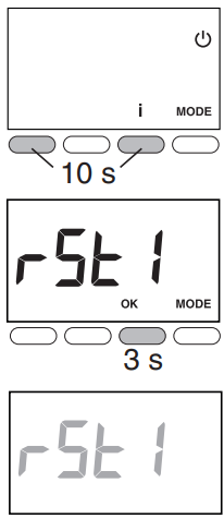
The system automatically returns to OFF mode.
Reference
Download Manual:
Delta Dore 8000-TA-BUS Zone Thermostat Installation Instructions
Delta Dore 8000-TA-BUS Zone Thermostat Installation Instructions
Leave a Reply