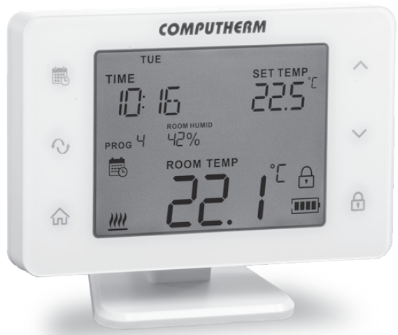
COMPUTHERM Q20RF Programmable Wireless Thermostat
A GENERAL DESCRIPTION OF THE THERMOSTAT
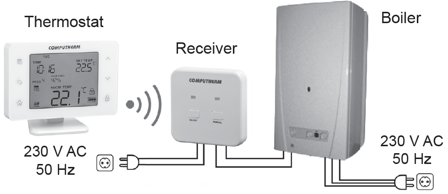
The COMPUTHERM Q20RF type switch mode room thermostat is suitable for regulating a large majority of boilers, air conditioners, humidifiers and dehumidifiers in circulation. It can easily be connected to any gas boiler, air conditioner, humidifier and dehumidifier with a two-wire room thermostat connection point and to other electrical devices, regardless of whether the device has a 24 V or 230 V control circuit.
The device can be programmed as needed so that the heating/cooling or humidifier/dehumidifier system heats/cools and humidifies/dehumidifies your apartment or office to the desired temperature or humidity at the times you want, and it contributes to the reduction of energy costs in addition to providing comfort. Separate independent daily programs can be created for each day of the week. For each day, besides 1 fixed switching time.
(PROG 0) 10 freely adjustable (in 10 minutes increments) switching times (PROG 1– PROG 10) can be set, and a different temperature (in 0.5 °C increments) and humidity (in 1 percent increments) can be assigned to every switching times. The device is composed of two units: a portable control unit (thermostat) and a receiver unit that controls the device to be regulated. There is a wireless (radio frequency) connection between the two units therefore there is no need to lay a cable between the thermostat and the device to be regulated. The two units are practically in a synchronized state set at the factory. The thermostat and its receiver have their own safety code which guarantees secure operation of the device. For installation and connection of the receiver unit and its synchronisation with the thermostat please refer to Chapter 5. To extend the lifetime of batteries, the thermostat will not transmit signals continuously. Instead, it will repeat its relevant switch command every 5 minutes. Therefore, control is ensured even after a blackout.
The portability of the thermostat offers the following advantages:
- no need to lay a cable, which is especially advantageous when old buildings are being modernized,
- the optimal location of the device can be selected during operation,
- it is also advantageous when you intend to locate the thermostat in different rooms in the course of the day (e.g. in the living room during the day but in the bedroom at night).
The effective range of the transmitter incorporated in the thermostat is approximately 50 m in open terrain. This distance may become considerably shorter within a building, especially when a metal structure, reinforced concrete or adobe wall stands in the way of radio waves.
This wireless (radio-frequency) thermostat can also be easily extended with the COMPUTHERM Q1RX socket if needed, with which the thermostat is able to control any electrical device (e.g. fan heaters, pumps, zone valves, etc.) operating on 230 V (50 Hz; max. 16 A) according to the room temperature. (Detailed description of the COMPUTHERM Q1RX socket and usage suggestions can be found on our website www.computherm.info.)
The COMPUTHERM Q20RF thermostat can be used as an extension to the COMPUTHERM Q5RF or Q8RF multi-zone devices. The simultaneous use of several COMPUTHERM room thermostats and one COMPUTHERM Q4Z or Q10Z zone controller provides the possibility for the thermostats to also control a pump or a zone valve in addition to starting the heater or cooler. This way it is easy to divide a heating / cooling system into zones, thanks to which the heating/cooling of each room can be controlled separately, thus greatly increasing comfort. Furthermore, the zoning of the heating / cooling system will greatly contribute to the reduction of energy costs, as due to this only those rooms will be heated / cooled at any time where it is required.
IMPORTANT WARNINGS AND SAFETY RECOMMENDATIONS
- Before starting to use the device, please study carefully the instructions for use and follow strictly the instructions therein.
- The thermostat is designed for business or household (non-industrial) use, it can be used to control any electrical device, the power of which does not exceed 1.38 kW (load capacity: max. 30 V DC / 250 V AC; 6 A [2 A inductive load]).
- This device is designed for indoor use. Do not use in wet, chemically aggressive or dusty environments.
- This device is a thermostat that communicates wirelessly. To avoid signal interference, keep it away from electrical equipment that may interfere with this communication.
- The manufacturer will assume no responsibility for any possible direct or indirect damages or income losses incurring during the use of the device.
- The device does not work without power, but the thermostat can remember the settings. In the event of a possible power supply failure (power cut/battery replacement), it can continue to operate without any external intervention after the power supply is restored. If you intend to use the device in an environment where there are frequent power outages, we recommend that you regularly check the correct operation of the thermostat for safety reasons.
- Before starting the actual control of the device connected to the thermostat, make sure that the device works perfectly and can be operated reliably even when controlled by the thermostat.
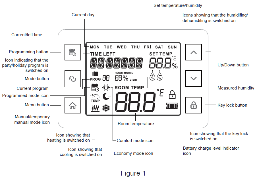
INFORMATION APPEARING ON THE DISPLAY OF THE THERMOSTAT
LOCATION OF THE THERMOSTAT AND RECEIVER UNIT
It is reasonable to locate it in a room used regularly or for many hours per day so that it is in the direction of natural ventilation in the room but protected from drought or extreme heat (e.g. direct sunlight, refrigerator, chimney, etc). Its optimal location is 0.75 – 1.5 m above floor level. It is advisable to install the receiver of the COMPUTHERM Q20RF in wet, chemically aggressive or dusty environment. thermostat near the boiler, in a place protected from moisture, dust, chemicals and heat. When choosing the location of the receiver, also consider that a propagation of radio waves is prevented by heavy metal objects (e.g. boiler, buffer tank, etc.) or can be adversely affected by metal building structures. If you have it possibility, in order to ensure an interference-free radio frequency connection, we recommend that the receiver be away from the boiler and another large install it at a distance of at least 1 – 2 m from metal structures, at a height of 1.5 – 2 m. We recommend that you check the reliability of the radio frequency connection in the selected location before installing the receiver.
ATTENTION: Do not install the receiver under the boiler cover or in the immediate vicinity of hot pipes, as this may damage the device’s components and endanger the wireless (radio frequency) connection. To avoid electric shock, entrust the connection of the receiver to the boiler to a specialist.
IMPORTANT WARNING: If the radiator valves in your flat are equipped with a thermostatic head, adjust it to maximum temperature or replace the thermostatic head of the radiator valve with a manual control knob in the room where the room thermostat is to be located, otherwise the thermostatic head may disturb the temperature control of the flat.
PUTTING THE THERMOSTAT INTO OPERATION, BASIC SETTINGS
Commissioning the thermostat
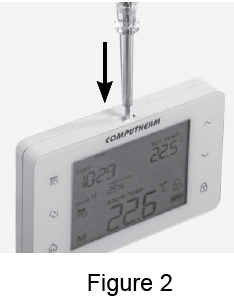
- Pressing the lock on the upper side of the housing of the thermostat, remove the back cover of the thermostat as shown in the figure 2.
- The battery compartment is in the inner side of the front panel of the housing. Insert 2 AA alkaline batteries (LR6 type) in accordance with the diagram in the battery compartment.
Warning: Alkaline batteries may only be used for this appliance. Carbon-zinc batteries known as durable or long life batteries and chargeable accumulators are not suitable for the operation of this appliance. Icon![]() appearing on the display to indicate low battery voltage warns reliably that the batteries should be replaced only when alkaline batteries are used.
appearing on the display to indicate low battery voltage warns reliably that the batteries should be replaced only when alkaline batteries are used.
After the batteries have been inserted, the display flashes the day, time, program number, adjusted and measured temperatures, measured humidity level and icons showing the operating mode and battery power level. After inserting the batteries, snap the front panel of the device into the rear panel and touch the![]() button. After touching the
button. After touching the ![]() button, the display stops flashing, the thermostat goes to the main screen and the setting process can be started.
button, the display stops flashing, the thermostat goes to the main screen and the setting process can be started.
Connection of the receiver unit
WARNING: The device must be installed and connected by a qualified professional. Before installing, make sure that neither the thermostat or the device to be controlled is connected to the 230 V mains voltage. Modifying the thermostat can cause electric shock or product failure.
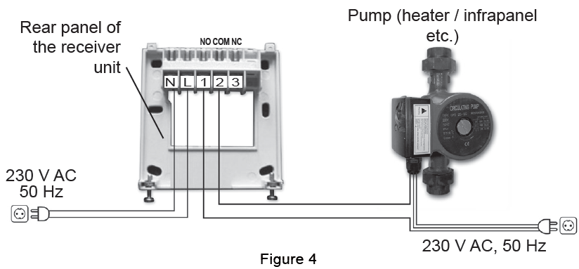
Unscrew the two screws at the bottom of the receiver unit without removing them. Following this, remove the front panel of the receiver unit then fix the back panel to the wall in the vicinity of the boiler with the screws provided. The marks of the connections are pressed into the plastic above the connection points: N, L, 1, 2, and 3.
Connecting the controlled device to the receiver unit
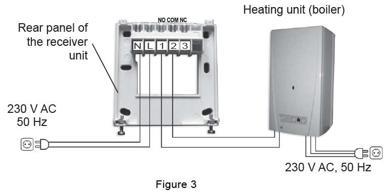
The receiver unit controls the boiler or air conditioner through a potential-free alternating relay whose connection points are: 1 (NO), 2 (COM) and 3 (NC). Connect the two connection points of the heating or cooling equipment to be controlled to the normally open 1 (NO) and 2 (COM) terminals of the relay, as shown on the below figure.
If you would like to operate an old boiler or any other device that has no connection points for thermostats, then the 1 (NO) and 2 (COM) connection points of the thermostat should be connected to the mains cable of the device, similarly as a switch would be connected, as shown in the figure below.
ATTENTION: Always consider the load ability of the receiver unit and follow the manufacturer’s instructions of the heating or cooling equipment. The device must be installed and connected by a qualified professional!
The voltage appearing at terminals 1 (NO) and 2 (COM) depends only on the system being controlled, therefore the dimensions of the wire are determined by the type of the device to be controlled. The length of the wire is of no significance, the receiver unit may be installed either near the boiler or far away from it, but do not install it under the housing of the boiler.
Connecting the receiver unit to the mains
230 V supply voltage should be applied to the receiver unit. This ensures power supply to the receiver unit but this voltage does not appear on the output connection points (1, 2 and 3). The neutral conductor and the phase line of the network should be connected to points N and L (Figure 3; no need to check correct phase sequence). There is no need for earth connection because the product is equipped with double insulation.
Putting the receiver unit into operation
Turn the power on for the receiver unit. After a few seconds the wireless (radiofrequency) system (thermostat and receiver unit) are tuned into the operating frequency. As a test, in heating mode touch the![]() button of the thermostat several times until the set temperature exceeds the room temperature by at least 0.5 °C. Following this, within a few seconds, the
button of the thermostat several times until the set temperature exceeds the room temperature by at least 0.5 °C. Following this, within a few seconds, the ![]() icon showing the power-on state must appear on the display of the thermostat. At the same time, on the receiver unit the red LED should switch on to indicate that the receiver unit has accepted the command of the transmitter (thermostat). If that does not happen, the system must be tuned again. You can do it as described in Chapter 7.8 If the distance between the receiver and the transmitter too large due to local circumstances and this makes the wireless (radio frequency) connection uncertain, install the receiver unit closer to the location of the thermostat or use a COMPUTHERM Q2RF radiofrequency signal repeater to extend the transmission distance.
icon showing the power-on state must appear on the display of the thermostat. At the same time, on the receiver unit the red LED should switch on to indicate that the receiver unit has accepted the command of the transmitter (thermostat). If that does not happen, the system must be tuned again. You can do it as described in Chapter 7.8 If the distance between the receiver and the transmitter too large due to local circumstances and this makes the wireless (radio frequency) connection uncertain, install the receiver unit closer to the location of the thermostat or use a COMPUTHERM Q2RF radiofrequency signal repeater to extend the transmission distance.
OPERATION OF THE THERMOSTAT
OPERATION OF THE THERMOSTAT THAT HAS BEEN PUT INTO OPERATION
The thermostat controls (manually or via programming) the devices (e.g. gas boiler, pump or dehumidifier) connected thereto on the basis of the humidity/temperature measured by it and being set, considering the switching sensitivity of the thermostat (±0.2 °C/±1.0% according to factory default) This means that when the thermostat is set to heating mode and 22 °C then at switching sensitivity of ±0.2 °C the connection points of the output relay of the receiver unit 1 (NO) and 2 (COM) close at a temperature below 21.8 °C (the heating system switches on), and open at a temperature above 22.2 °C (the heating system switches off). In cooling mode the relay switches conversely.
When the thermostat is set to humidifying mode and to 60%, then at switching sensitivity of ±1.0% the output relay of the receiver unit 1 (NO) and 2 (COM) close at a relative humidity below 49% (the humidifier switches on) and open at a relative humidity above 51% (the humidifier switches off). In dehumidifying mode the relay switches conversely. The closed state of the connection points 1 (NO) and 2 (COM) of the output relay is indicated by the![]() ,
,![]() ,
,![]() or
or![]() icons appearing on the display of the device, according to the selected mode.
icons appearing on the display of the device, according to the selected mode.
SETTINGS
ATTENTION: According to factory default setting the key lock of the thermostat automatically switches on after 30 seconds which is indicated by the![]() icon that appears in the bottom right corner of the display. To unlock the
icon that appears in the bottom right corner of the display. To unlock the ![]() keyboard, touch the button for 2 seconds
keyboard, touch the button for 2 seconds![]() until the icon disappears from the display.
until the icon disappears from the display.
The thermostat allows a number of setting options by which the operation of the thermostat can be tailored to your liking. You can enter the setting menu of the thermostat by pressing the button![]() for 2 seconds. Then the continuously illuminated time and the flashing English abbreviation of the relevant day (Monday: MON; Tuesday: TUE; Wednesday: WED and so on) appear on the screen. In the setting menu you can modify the current setting with buttons
for 2 seconds. Then the continuously illuminated time and the flashing English abbreviation of the relevant day (Monday: MON; Tuesday: TUE; Wednesday: WED and so on) appear on the screen. In the setting menu you can modify the current setting with buttons ![]() and
and![]() touching the
touching the ![]() button you can move to the next setting.
button you can move to the next setting.
The currently modifiable setting is flashing on the display. After the current day and exact time have been set, you can perform additional settings as follows:
|
Displayed abbreviation |
Description of the setting |
Setting options |
Factory default setting |
Detailed description |
|
FUNC |
Operating mode |
HEA: heating |
HEA |
Chapter 7.1. |
| COO: cooling | ||||
| HUM: humidifying | ||||
| DEH: dehumidifying | ||||
|
PROGRAM |
Switching on and off of programmed mode |
OFF: Switched off. In this case the thermostat is working in a manually set Economy mode or comfort mode. |
ON |
Chapter 7.2. |
| ON: Switched on. In this case the thermostat is working according to a pre-set program or manual mode. | ||||
|
T UNIT |
Temperature unit |
°C |
°C |
— |
| °F | ||||
|
HYSTER |
Switching sensitivity |
±0.1 – ±1.0 °C | ±0.2 °C |
Chapter 7.3. |
| ±0.2 – ±2.0 °F | ±0.4 °F | |||
| ±1 – ±5% RH | ±1% RH | |||
|
MIN |
Minimum adjustable temperature/ humidity |
5 – 45 °C | 5 °C |
— |
| 41 – 97 °F | 41 °F | |||
| 0 – 98% RH | 30% RH | |||
|
MAX |
Maximum adjustable temperature/ humidity |
5 – 45 °C | 35 °C |
— |
| 41 – 97 °F | 95 °F | |||
| 1 – 99% RH | 80% RH | |||
|
T CALIB |
Calibration of the temperature sensor |
-3.0 – +3.0 °C | 0.0 °C |
Chapter 7.4. |
| -6.0 – +6.0 °F | 0.0 °F |
| Displayed
abbreviation |
Description of the setting | Setting options | Factory default setting | Detailed
description |
| H CALIB | Calibration of the humidity sensor | -10 – +10% RH | 0% RH | Chapter 7.5. |
|
H LIMIT |
Setting humidity limit in case of cooling |
OFF: function switched off |
80% RH |
Chapter 7.6. |
| 30-99: if the measured humidity is higher than the set value then the cooling system switches off | ||||
|
A LIGHT |
Automatic backlight |
OFF: switched off |
ON |
— |
| ON: switched on (backlight switches on for 10
seconds after any button has been pressed) |
||||
| BRIGHT | Backlight brightness | 0 – 10 | 7 | — |
|
B LIGHT |
Backlight of the buttons |
OFF: switched off |
ON |
— |
| ON: switched on (backlight of the keys switches on and off simultaneously with the backlight of the display) | ||||
|
B SOUND |
Acoustic signal when buttons are touched |
OFF: switched off |
OFF |
— |
| ON: switched on | ||||
|
LOCK |
Automatic key lock |
OFF: automatic key lock is switched off |
ON |
— |
| ON: automatic key lock is switched on (the key lock is activated 30 seconds after touching the last button) | ||||
|
PUMP |
Switching on and off of the pump
protection function |
OFF: switched off |
OFF |
Chapter 7.7. |
| ON: switched on |
| Displayed
abbreviation |
Description of the setting | Setting options | Factory default setting | Detailed
description |
|
SYNC |
Synchronisation with the receiver unit(s) |
–: moving to the next setting after touching the button |
— |
Chapter 7.8. |
|
SYN: the thermostat is synchronised with the receiver(s) set to synchronisation mode in its environment after touching the button |
||||
|
TEST |
Testing wireless communications |
–: moving to the next setting after touching the button |
— |
Chapter 7.9. |
| ON: the thermostat changes to test mode after touching the button | ||||
|
RESET |
Restoring factory default settings |
–: saving the settings and
exiting the settings menu after touching the button |
— |
Chapter 7.10. |
|
ON: restoring factory default setting after touching button |
To exit the setting menu and save the settings:
- touch the
 button, or
 - wait for 30 seconds until the display of the thermostat is reset to the default screen, or
- go through the settings with the
 button.
Selecting the operating mode (FUNC)
You can easily switch between heating (HEA; factory default setting), cooling (COO), humidifying (HUM) and dehumidifying (DEH) modes. The connection points of the output relay of the receiver unit 1 (NO) and 2 (COM) close at temperatures below those set in the heating mode, at temperatures above those set in the cooling mode, below the humidity level set in the humidifying mode and above the humidity level set in the dehumidifying mode (taking the switching sensitivities into account).
Switching on and off of the programmed mode (PROGRAM)
The thermostat can be used in both programmed and non-programmed modes. When the programmed mode is on, in automatic (programmed) mode the thermostat controls the devices connected thereto according to the pre-set program, but it can be switched to manual mode by touching the ![]() button, and in this case it will constantly control the devices according to the temperature/humidity set manually, regardless of the pre-set program. When you switch off the programmed mode, you can set two independent temperatures/humidity levels (comfort and economy), and you can easily switch between the two modes by touching the
button, and in this case it will constantly control the devices according to the temperature/humidity set manually, regardless of the pre-set program. When you switch off the programmed mode, you can set two independent temperatures/humidity levels (comfort and economy), and you can easily switch between the two modes by touching the![]() button. In this case the devices connected to the thermostat cannot be controlled according to the pre-set program.
button. In this case the devices connected to the thermostat cannot be controlled according to the pre-set program.
Selecting switching sensitivity (HYSTER)
The switching sensitivity can be adjusted. By modifying this value, you can define the difference below/above the set temperature/humidity where the thermostat should switch on/off the device connected thereto. The smaller this value, the more stable is the inner temperature/humidity in the room and the comfort improves. Switching sensitivity does not affect the heat loss of the room (building) and vapour formation.
When higher comfort level is needed, it is reasonable to select the switching sensitivity so that it ensures as stable inner temperature/humidity as possible. On the other hand, two frequent starts and stops of the controlled device should be avoided because this may reduce the efficiency and lifetime of the device. The switching sensitivity can be set in the temperature range of ±0.1 °C to ±1.0 °C / ±0.2 to ±2.0 °F and in the humidity range of ±1 to ±5% RH. Apart from some special cases, we propose to use ±0.1 °C or ±0.2 °C (factory default) when a heating/cooling system should be controlled. For humidification/ dehumidification, we recommend you use a switching sensitivity of ±1% (factory default) or ±2%. For more information about switching sensitivity please refer to Chapter 6.
Calibration of the temperature sensor (T CALIB)
The accuracy of the thermometer of the thermostat is ±0,5 °C. The temperature displayed by the thermostat can be modified by maximum ±3.0 °C / ±6,0 °F compared to the temperature measured by the temperature sensor, in increments of ±3.0 °C / ±6.0 °F or 0.1 °C / 0.1 °F.
Calibration of the humidity sensor (H CALIB)
- The accuracy of the humidity sensor of the thermostat is ±3% RH.
- The relative humidity displayed by the thermostat can be modified by maximum ±10% compared to the humidity measured by the sensor, in increments of 1%.
Setting the humidity limit for cooling (H LIMIT)
When a cooling system including surface cooling is controlled, it is important that the air in the room must not reach dew point because in this case condensation occurs which can cause serious damages. Using this function, you can set the humidity level above which the thermostat will stop cooling to prevent condensation.
Switching on and off of the pump protecting function (PUMP)
In order to prevent the pump from jamming, the activated pump protection function will start the devices connected thereto for 1 minute every day at 12:00 p.m. (noon), if switching was not done either on the respective day or on the previous day (e.g. during non-heating period). The pump protectionfunction only works when the controlled device is in operable condition.
Synchronisation with the receiver unit(s) (SYNC)
The thermostat and its receiver unit have been synchronized at the factory. When communication is not working between the two units they should be synchronized again. To do so, press and hold (for approx. 10 seconds) the “ON/OFF” button of the receiver unit until the green LED start to flash. Now the receiver unit is in synchronization mode. Then in the setting menu at function SYNC choose option “SYN” and move on with the ![]() button. Now the thermostat and the receiver unit are synchronized and the green LED on the receiver unit stops flashing. The two units remain synchronized even after a possible power failure or battery replacement.
button. Now the thermostat and the receiver unit are synchronized and the green LED on the receiver unit stops flashing. The two units remain synchronized even after a possible power failure or battery replacement.
Attention: If you wish to synchronize several wireless COMPUTHERM Q series products with one thermostat at the same time or to synchronize a single wireless COMPUTHERM Q series product with several thermostats simultaneously, for detailed information please read Chapter 12.2.
Testing wireless communications (TEST)
With the “TEST” function you can check whether the wireless (radio frequency) connection between the thermostat and its receiver unit functions properly. To this end choose the “ON” option at the “TEST” function in the setting menu and move on with the![]() button. Following this, the thermostat sends power on and off control signals alternating every 5 seconds for 2 minutes.
button. Following this, the thermostat sends power on and off control signals alternating every 5 seconds for 2 minutes.
In the meantime, ![]() /
/ ![]() /
/![]() /
/ ![]() icons appear then go out on the display, and the “tE5T” notice is continuously visible in the place of the exact time. Detection of the control signal is indicated by the illumination and extinguishing of the red LED on the receiver unit. If the receiver fails to detect the signals sent by the thermostat then the receiver unit is out of the range of the wireless (radio frequency) transmitter and the two units should be placed closer to each other. If it is not feasible due to local circumstances, use a COMPUTHERM Q2RF radio-frequency signal repeater to extend the transmission distance. To exit “TEST” function touch the
icons appear then go out on the display, and the “tE5T” notice is continuously visible in the place of the exact time. Detection of the control signal is indicated by the illumination and extinguishing of the red LED on the receiver unit. If the receiver fails to detect the signals sent by the thermostat then the receiver unit is out of the range of the wireless (radio frequency) transmitter and the two units should be placed closer to each other. If it is not feasible due to local circumstances, use a COMPUTHERM Q2RF radio-frequency signal repeater to extend the transmission distance. To exit “TEST” function touch the![]() button and the thermostat will return to the mode where it was before this function has been switched on.
button and the thermostat will return to the mode where it was before this function has been switched on.
Restoring factory default setting (RESET)
This function resets all settings of the thermostat to factory default. To restore factory default setting choose option “RES” at “RESET” function in the setting menu and move on with the![]() button. Leaving the “RESET” function in default state (
button. Leaving the “RESET” function in default state (![]() ) after touching the
) after touching the ![]() button the thermostat saves the settings, exits this menu, and after returning to the home screen continues its operation according to the operating mode set beforehand.
button the thermostat saves the settings, exits this menu, and after returning to the home screen continues its operation according to the operating mode set beforehand.
OPERATING MODES OF THE DEVICE
The thermostat has the following four operating modes:
- When the programmed mode is off
- Economy mode (
 ; Chapter 8.1.)
 - Comfort mode (
 ; Chapter 8.2.)
- Economy mode (
- When the programmed mode is on
- Manual mode (
 ; Chapter 8.3.)
 - Automatic (programmed) mode(
 ; Chapter 8.4.)
- Manual mode (
Touching the![]() button you can switch between the modes. When you intend to operate your device temporarily in a way other than the set default mode (e.g. on the occasion of a family gathering, a holiday or a winter vacation) then you can choose from the following 3 supplementary operating modes:
button you can switch between the modes. When you intend to operate your device temporarily in a way other than the set default mode (e.g. on the occasion of a family gathering, a holiday or a winter vacation) then you can choose from the following 3 supplementary operating modes:
- Temporary manual mode until the next program switching (
 ; Chapter 8.5.) (only in case of programmed mode)
 - Temporary manual mode for 1 to 99 hours (party program) (
 ;Chapter 8.6.)
 - Temporary manual mode for 1 to 99 days (holiday program) ( ;Chapter 8.7.)
The thermostat can be used for control on the basis of temperature and humidity alike. In every mode the temperature/humidity to be maintained by the thermostat can be defined in 0.5 °C / 0.5 °F / 1% increments within the intervals specified in the settings.
Economy mode (![]() )
)
In economy mode the thermostat provides the economical (e.g. nighttime) temperature/humidity corresponding to the set temperature/humidity in the vicinity of the place of installation. Using the ![]() and
and![]() buttons these values can be modified at any time while this operating mode is used.
buttons these values can be modified at any time while this operating mode is used.
Comfort mode (![]() )
)
In comfort mode the thermostat provides the comfort (e.g. daytime) temperature/humidity corresponding to the set temperature/humidity in the vicinity of the place of installation. Using the![]() and
and ![]() buttons these values can be modified at any time while this operating mode is used.
buttons these values can be modified at any time while this operating mode is used.
Manual mode (![]() )
)
In manual mode the thermostat provides the temperature/humidity corresponding to the set temperature/humidity in the vicinity of the place of installation until the next intervention. Using![]() and
and![]() buttons these values can be modified at any time while this operating mode is used.
buttons these values can be modified at any time while this operating mode is used.
Programmed mode ( )
A description of programming
- Programming includes setting the switching times and selecting associated temperature/humidity levels. The devices can be programmed for a one week period. Its operation is automatic, repeating the set switchings cyclically every 7 days. For each day, 1 fixed switching time (PROG 0) and 10 optional switching times (PROG 1 – PROG 10) can be set. A different temperature/humidity value can be assigned to every switching time. Every temperature/humidity level set to a switching will remain valid until the time of next switching. For example, temperature/humidity values set to PROG switching time will be kept until the time of PROG switching. The temperature/humidity level selected to PROG 1 switching will remain valid from the time of PROG 1 switching to the time of next switching (PROG 2).
- The time of PROG 0 switching is 00:00 that cannot be modified, only the temperature assigned thereto can be changed to meet individual requirements. In default setting the thermostat carries on only 1 switching (PROG 0) every day, which is valid from 00:00 to 00:00 on the following day.
- Remark: 1 switching a day (factory default setting) only makes sense if you need uniform temperature all day. (For example, if you want to maintain a continuous economical temperature, e.g. 16 °C, on weekdays, while you wish to maintain a comfort temperature, e.g. 22 °C, on weekend days). In other cases, it is advisable to activate several switchings a day for comfort and energy-saving reasons. Considering energy savings, it is recommended that the comfort temperature is activated only during the periods when the room is being used, because lowering the room temperature by 1 °C will result in approx. 6 percent energy savings on average during a heating season.
- In default position PROG 1– PROG 10 switchings are inactive (their time is
 ), but can be activated according to needs. The times of PROG 1 – PROG 10 switchings are freely adjustable in 10 minutes increments between OO:10 és 23:5O with the proviso that the device enables settings of times only in ascending chronological order so that there should be at least 10 minutes difference between switching times. The min. 10 minutes difference between switching times remains even when you modify the times of a previously set program in order to avoid coincidence or overlap of switching times. In this case the device pushes forward the respective times so that the min. 10 minutes difference always remains. If due to time modifications the time of one or more switchings is moved after the last adjustable daily switching time (23:5o) it or they will become inactive automatically.
 - To enter programming mode touch the button for 2 seconds. During programming the values being set (date, time, temperature/humidity) flash on the display of the device. The values are always modified by using buttons
 and
and  on the front panel of the device. Use the button to record the set value and to move on. The set program can be saved by touching the button. A more detailed description of programming can be found in Chapter 8.4.2.
 - If there are days of the week on which you intend to use the same program then it is sufficient to write this program only once because it can be easily adopted to an optional day with the help of the “COPY” function according to Chapter 8.4.3. If you want the same program for each day or intend to write programs to be used from Monday to Friday and from Saturday to Sundays which are different but are the same on a given day, you can program the device this way as described in Chapter 8.4.2. But keep in mind that when you programmed several days similarly this way, you can modify their program only together. Therefore, if you want a program that differs from the others even for a single day, you should program the days separately, and the repeated programs can be copied with the “COPY” function.
- Separate programs can be written for cooling, heating, humidifying and dehumidifying modes, and the thermostat will save them when switching between modes. Therefore you can use your thermostat in more than one mode, and you do not have to rewrite the program according to the operating mode whenever switching between modes.
Steps of programming the device
- Touch the button to move the thermostat to home screen then touch the button for 2 seconds. Then the device gets to programming mode and the syllable indicating the relevant day(s) flashes in the top line of the display.
- Using the and buttons select the day to be programmed (the MON syllable indicates Monday, the TUE and WED syllables indicate Tuesday and Wednesday, and soon). If you wish to write the same program for every day of the week it is reasonable to select all days of the week at the same time (indicated by simultaneous flashing of syllables MON, TUE, WED, THU, FRI, SAT, and SUN) instead of programming the days of the week separately. If you want to write programs to be used from Monday to Friday and from Saturday to Sundays which are different but are the same on a given day, it is advisable to choose the 5+2 programming mode (it is indicated by simultaneous flashing of syllables MON, TUE, WED, THU and FRI, while syllables SAT and SUN are shown continuously). After the day(s) has/have been selected, touch the button to save the setting and move on.
- Then the device offers to set the temperature/humidity of PROG 0 switching that belongs to the day(s) selected. During the setting process the currently set value (in case of heating function the default setting is 20 °C) is flashing. Using and button set the desired temperature/humidity then touch the button to record the setting and move on.
- This is followed by the next step of programming, i.e. setting the start time of PROG 1 switching that belongs to the selected day(s), and the display of the device will flash the time value (the default setting is
) to be set. Using and buttons on the front panel of the device set the desired time of PROG 1 setting then touch the button to record the setting and move on. - Now the programming process is continued by setting the temperature belonging to PROG setting and the display flashes the value to be set (in case of heating function the default setting is 20 °C). Using and buttons set the desired temperature/humidity of PROG 1 setting then touch button to record the setting and move on.
- Then the device offers to set the time of PROG setting, and the display of the device will flash the time value (the default setting is ) to be set. To set switchings PROG 2 — PROG 10(in the same was as PROG 1 has been set) repeat steps “d” – “e”. If you do not intend to activate further switching options for the day(s) selected in addition to those that have already been set then touch the button, without resetting the start date of the next offered switching from the default position. Then programming of the respective day(s) is completed and the device immediately offers selection of a new day and programming can be continued from step.“b”. If you have set all switchings from PROG 0 to PROG 10 for the selected day(s) then, after the temperature/humidity of switching PROG 10 has been set, programming the respective day(s) is finished and the device immediately offers selection of a new day and programming can be continued from step “b”.
- You can save and finish programming by touching the button. The device will automatically acknowledge settings even if no button is touched for 1 minute. Then the display of the device returns to the home screen.
If you would like to copy the program written for the day selected in section “b” to another day/other days you can easily do it by means of the “COPY” function as described in Chapter 8.4.3.
The use of “COPY” function (copying the program of a day to another day or other days)
Attention: The “COPY” function may only be used for programming the days of the week separately!
Touch the![]() button to move the display of the thermostat to the home screen then enter the programming menu by touching the
button to move the display of the thermostat to the home screen then enter the programming menu by touching the ![]() button for 2 seconds. Following this, touch the
button for 2 seconds. Following this, touch the ![]() button for 2 seconds to activate the “COPY” function. The state of being ready for copying the program is indicated by the “COPY” notice appearing in the place of hour characters and flashing of the syllable showing the day being programmed.
button for 2 seconds to activate the “COPY” function. The state of being ready for copying the program is indicated by the “COPY” notice appearing in the place of hour characters and flashing of the syllable showing the day being programmed.
- Using and buttons select the day whose program you intend to copy to another day/other days.
- Touch the button to copy the program of the selected day. After copying has been completed, the syllable indicating the copied day stops flashing and becomes continuously visible.
- Using és buttons select the day to which you wish to copy the day that has been copied previously. Thy syllable indicating the day being selected will be flashing during the setting.
- After you have chosen the day to which you wish to copy the day that has been copied previously touch the button to copy the program. Then the syllable indicating the day to which you have copied the program also becomes continuously visible and its flashing stops. Using buttons and you can select additional days to which you can copy the program that has been copied previously with the button.
- You can save the copied programs by touching the button for 2 seconds. The thermostat returns to programming mode and you can continue to program the device. The thermostat saves program modifications and returns to the home screen after touching the button or after 15 seconds.
- You can perform further copying of programs according to your need by repeating the steps described above.
Modifying the programs of the device
- Set values can be freely modified at any time by repeating the programming steps.
- You can increase the number of switchings activated previously as you like according to Chapter 8.4.2.
- You can cancel a switching activated beforehand so that during the modification of the time of switching with buttons and you reset the time set previously to factory default () or touch the button for 2 seconds. Touch the button to cancel respective switching. If you cancelled an intermediary number the remaining switchings will be renumbered.
- If you want to finish modification of the switchings of the selected day then repeatedly touching the button step through the switchings of the respective day until the sign of the respective day start flashing on the screen. Now you can continue modifications by selecting the next day.
- Touching the button you can save and finish modifications. The device will automatically acknowledge the settings even if no button is touched for 1 minute. Then the display of the device returns to the home screen.
- If you intend to write a whole new program then cancel the set programs as described above or reset the device to factory default as described in Chapter 7.10. In this case the device should be set and programmed again as described in Chapters 7. and 8.4.
Program inspection
- Touch the button to move the display of the thermostat to the home screen then touch the button. Syllable(s) indicating the day(s), the symbol of the PROG 0 switching, the 00:00 time and the temperature/humidity value appear on the screen (none of the values is flashing).
- Repeatedly touching the button you can check the values of PROG 1, PROG 2 etc. switchings that belong to the respective day(s). Using and buttons you can switch between the days. If during the programming process you programmed every day of the week (MON, TUE, WED, THU, FRI, SAT, and SUN), simultaneously then you can view the programs of all days only together. If you selected the 5+2 (MON, TUE, WED, THU, FRI, SAT and SUN) programming mode, you can inspect either programming of the first 5 days (MON, TUE, WED, THU, and FRI) or of the last two days (SAT SUN) and you can swich between these options with and buttons.
- After checking the program, touching the button you can return to the home screen (if no button has been touched for 15 seconds, the display will automatically return to the home screen).
Temporary manual mode until the next program switching
The temporary manual mode can only be used in programmed mode until the next program switching. For activation, with buttons ![]() and
and![]() , modify the temperature/humidity set according to programming. After setting, the program number disappears and
, modify the temperature/humidity set according to programming. After setting, the program number disappears and![]() icon appears on the display, indicating that the thermostat will be operated by temporary manual control until the next program switching. Following this, the thermostat will maintain the modified temperature/humidity until the time of the next switching, and during this time the temperature and humidity can be freely modified with buttons
icon appears on the display, indicating that the thermostat will be operated by temporary manual control until the next program switching. Following this, the thermostat will maintain the modified temperature/humidity until the time of the next switching, and during this time the temperature and humidity can be freely modified with buttons![]() and
and![]() .
.
During the temporary manual mode the segments indicating the time on the display alternately show the exact time (TIME), and the time remaining in manual control (TIME LEFT) (e.g.4:o2, that is 4 hours and 2 minutes). After this time, the ![]() icon disappears and the device returns to the set program. If you wish to return to the set program before the switching time, touch the
icon disappears and the device returns to the set program. If you wish to return to the set program before the switching time, touch the![]() button.
button.
Temporary manual mode for 1 to 99 hours (party program)
The party program can be used in any default mode of the thermostat. For activation touch the ![]() button for 2 seconds. Then the
button for 2 seconds. Then the![]() icon appears on the display together with the “ H” notice in place of the exact time segments to show the duration of the party program in hours (the “ ” number that indicates the number of the hours is flashing to show that the duration is adjustable). Using
icon appears on the display together with the “ H” notice in place of the exact time segments to show the duration of the party program in hours (the “ ” number that indicates the number of the hours is flashing to show that the duration is adjustable). Using![]() and
and ![]() buttons the intended duration can be freely set between 1 and 99 hours. The set party program starts automatically and enters into effect after approx. 10 seconds. Then using
buttons the intended duration can be freely set between 1 and 99 hours. The set party program starts automatically and enters into effect after approx. 10 seconds. Then using ![]() and
and![]() buttons set the temperature to be maintained during the party program period. Until the expiry of the set period the device will maintain the temporary temperature/humidity that differ from the default mode and can be freely modified with buttons
buttons set the temperature to be maintained during the party program period. Until the expiry of the set period the device will maintain the temporary temperature/humidity that differ from the default mode and can be freely modified with buttons![]() and
and ![]() during the party program period.
during the party program period.
During the holiday program the segments indicating the hour on the display alternately show the exact time (TIME) and the number of days remaining in temporary manual control (TIME LEFT) (e.g. “ 3D ” that is 3 days). When the remaining time decreases below 24 hours then from then on the remaining time is displayed in the same as at the party program (e.g. 22: 18, that is 10:18 p.m.). After this time, the icon![]() disappears and the device returns to operation according to the mode used before the holiday mode. Touch the
disappears and the device returns to operation according to the mode used before the holiday mode. Touch the ![]() button if you wish to return to the previously used mode before the set time expires.
button if you wish to return to the previously used mode before the set time expires.
OPERATION OF BACKLIGHT
By factory default the backlight of the thermostat automatically switches on for 15 seconds after touching any button. Regardless of the automatic backlight, touching the ![]() button you can switch on/off the backlight. If you touch any button while the backlight is active, the backlight will go out only 10 seconds after the last button has been touched. You can modify the automatic backlight of the thermostat, the backlight of the keys and the backlight brightness as described in Chapter 7.
button you can switch on/off the backlight. If you touch any button while the backlight is active, the backlight will go out only 10 seconds after the last button has been touched. You can modify the automatic backlight of the thermostat, the backlight of the keys and the backlight brightness as described in Chapter 7.
You can switch off the control buttons of the thermostat to prevent the settings from accidental or unauthorized modifications. Touching the![]() button for 2 seconds you can lock and unlock the control buttons. The
button for 2 seconds you can lock and unlock the control buttons. The ![]() icon appearing/ disappearing in the right bottom corner of the display indicates the locked/unlocked state of the control buttons. By default setting the thermostat automatically locks the control buttons 30 seconds after the last button has been touched. This setting can be switched off as described in Chapter 7.
icon appearing/ disappearing in the right bottom corner of the display indicates the locked/unlocked state of the control buttons. By default setting the thermostat automatically locks the control buttons 30 seconds after the last button has been touched. This setting can be switched off as described in Chapter 7.
BATTERY REPLACEMENT
The average life span of the batteries is 1 year, but frequent use of backlight can shorten this period considerably. When the ![]() icon indicating low voltage supply flashes on the display, the batteries should be replaced (see Chapter 5.1.). The exact time should be set again after the batteries have been replaced, but the device saves the program that has been loaded as well as the settings even without batteries therefore there is no need to reprogram or reset them.
icon indicating low voltage supply flashes on the display, the batteries should be replaced (see Chapter 5.1.). The exact time should be set again after the batteries have been replaced, but the device saves the program that has been loaded as well as the settings even without batteries therefore there is no need to reprogram or reset them.
Attention: Only high-quality alkaline batteries may be used in the device. So called durable or long-life zinc-carbon batteries are unsuitable for the operation of the devices. The ![]() low battery icon appearing on the display warns the necessity of battery replacement reliably only when high quality alkaline batteries are being used.
low battery icon appearing on the display warns the necessity of battery replacement reliably only when high quality alkaline batteries are being used.
RECEIVER UNIT OF THE THERMOSTAT
Operation of the receiver unit, meaning of its LED signs
The receiver unit switches its potential-free output in accordance with the switching signals of the wireless Q series COMPUTHERM room thermostat(s) which is/are synchronized with the unit.
A green and a red LEDs indicates the operating condition of the receiver unit as detailed below:
- Continuous light of the green LED indicates the manual mode. If it is not lit, the receiver unit is in automatic mode (controlled by the thermostat).
- Flashing of the green LED indicates synchronized mode.
- Continuous light of the red LED indicates that the output is on.
Chapter 4. outlines optimal location of the receiver unit, its connection and commissioning are discussed in Chapters 5.2. and 5.3., testing of the wireless communication are found in Chapter 7.9., while the synchronization process and manual operating mode are described in the following sub-chapters.
Synchronizing the receiver unit(s) with one or more thermostats
The receiver unit and its thermostat were harmonized at the factory. If you find that the thermostat fails to control the receiver unit or you intend to control it with another COMPUTHERM Q series room thermostat (too), then they should be synchronized. Synchronize the thermostat as described in Chapter 7.8. If you intend to synchronize several wireless COMPUTHERM Q series receiver units/sockets with one thermostat then first set all receiver units to synchronization mode than perform the steps of synchronization.
If you wish to synchronize more than one thermostat with the receiver unit then repeat the previous steps with the other thermostats, too. When you reach the maximum permissible number of synchronizable products (12) then, after pressing the “ON/OFF” button for 10 seconds, the red and green LEDs on the product flash alternately three times. In this case, pressing the “ON/OFF” and “MANUAL” buttons for 10 seconds, the receiver unit should be set to the default position for the synchronization of the new thermostat. Then both LEDs light up for 2 seconds, indicating that the receiver unit is reset and the synchronization of the new thermostat can commence.
Attention: If you want a given thermostat not to control the receiver unit then synchronize the thermostat with another wireless COMPUTHERM Q series device, perform the steps of synchronization on the thermostat alone (without receiver unit), or reset the receiver unit to factory default as described above.
Manual control of the receiver unit
Pressing the “MANUAL” button disconnects the thermostat(s) from the receiver unit synchronized with it/them. Then the device connected to the thermostat can only be switched on and off manually, without any temperature/humidity control. The continuous light of the green LED indicates the manual mode. Pressing the “ON/OFF” button switches on or off the device connected to the receiver unit. (The red LED lights when the output is on). Pressing the “MANUAL” button again ceases manual control and resets automatic operation (controlled by thermostat) (the green LED goes out).
FREQUENTLY ASKED QUESTIONS
When you think that your appliance is operating incorrectly or encounter any problem while the appliance is being used then we recommend that you read Frequently Asked Questions (FAQ) available on our website, where we collected the problems and questions that most frequently occur while our appliances are being used, along with the solutions thereto: https://www.computherm.info/en/faq

The vast majority of the problems encountered can be solved easily by using the hints available on our website, without seeking professional help. If you have not found a solution to you problem, please pay a visit to our qualified service.
PRODUCT INFORMATION DATA SHEET
- Trademark: COMPUTHERM
- Model identifier: Q20RF
- Temperature control class: I. class
- Contribution to the efficiency of seasonal space heating: 1%
Remark
In addition to using modern temperature regulators, the following up-to-date regulation methods also contribute significantly to the improvement of the comfort provided by the heating network, the energy efficiency of the heating network and the coefficient of performance:
- By dividing the heating network into sections or zones (e.g. by means of COMPUTHERM Q4Z vagy Q10Z zone controller and the associated COMPUTHERM zone valves) and with their separate regulation we can ensure that every room (zone) is heated only when it is necessary. (You can obtain information on the establishment of the heating network and apparatuses and fittings needed for division into zones in our publication titled “Energy Savings and Comfort” which is also available on our website www.computherm.info
- Using programmable thermostats you can ensure that every room (zone) is just heated according to a timetable preset in accordance with the demands.
- Using modern modular heating devices equipped with an external temperature sensor the boiler can be operated at higher efficienty.
- Using low temperature heating networks (e.g. 60/40 °C) and condensing boilers the temperature of the flue gas leaving the boiler can be reduced, and this way fuel efficiency can be improved significantly.
TECHNICAL DATA
Technical data of the thermostat (transmitter):
- Temperature measurement range: 0 to 48 °C (in 0.1 °C increments) / 32 to 100 °F (in 0.1 °F increments)
- Humidity measurement range: 0 to 99% RH (in 1.0% increments)
- Adjustable temperature range: 5 to 45 °C (in 0.5 °C- increments) / 41 to 97 °F (in 0.5 °F increments)
- Adjustable humidity range: 0 to 99% RH (in 1.0% increments)
- Temperature measurement accuracy: ±0.5 °C / ±0.9 °F
- Humidity measurement accuracy: ±3% RH
- Temperature calibration range: ±3 °C (in 0.1 °C increments) / ±6 °F ( in 0.1 °F increments)
- Humidity calibration range: ±10% RH (in 1% increments)
- Optional switching sensitivity: ±0.1 °C – ±1.0 °C / ±0.2 °F – ±2.0 °F / ±1% – ±5% RH
- Battery voltage: 2 x 1.5 V alkaline batteries (LR6 type; AA size)
- Battery lifetime: approx. 1 year
- Storage temperature: -10 °C to +50 °C
- Operating temperature: 0 °C to +48 °C
- Operating humidity: 5% to 90% (without condesation)
- Protection against environmental impacts: IP30
- Operating frequency: 868,35 MHz
- Transmission distance: approx. 50 m in open terrain
- Dimensions: 125 x 82 x 24.5 mm (W x H x D) (without holder)
- Weight: 134 g
- Temperature and humidity sensor type: GXCAS GXHT30 digital sensor
Technical data of the receiver unit:
- Power supply voltage: 230 V AC, 50 Hz
- Switchable voltage: max. 30 V DC / 250 V AC
- Switchable current: 6 A (2 A inductive load)
- Storage temperature: 10 °C to +50 °C
- Operating humidity: 5 % to 90 % (without condesation)
- Protection against environmental impacts: IP30
- Standby mode: max. 0.5 W
- Dimensions: 90 x 90 x 30 mm (W x H x D)
- Weight: 126 g
Total weight of the device: approx. 351 g (thermostat + receiver + holder)
The COMPUTHERM Q20RF type thermostat complies with the requirements of directives RED 2014/53/EU and RoHS 2011/65/EU.
![]()

Manufacturer
- Manufacturer: QUANTRAX Ltd.
- Fülemüle u. 34., Szeged, H-6726, Hungary
- Phone: +36 62 424 133
- Fax: +36 62 424 672
- E-mail: [email protected]
- Web: www.quantrax.hu
- www.computherm.info
- Origin: designed in the EU, manufactured in China
Copyright © 2022 Quantrax Ltd. All rights reserved.
Reference:
DOWNLOAD MANUALS:
COMPUTHERM Q20RF Programmable Wireless Thermostat Operating Instructions
![]()
COMPUTHERM Q20RF Programmable Wireless Thermostat Operating Instructions