
COMPUTHERM E400RF Wi-Fi Thermostat
A GENERAL DESCRIPTION OF THE THERMOSTAT
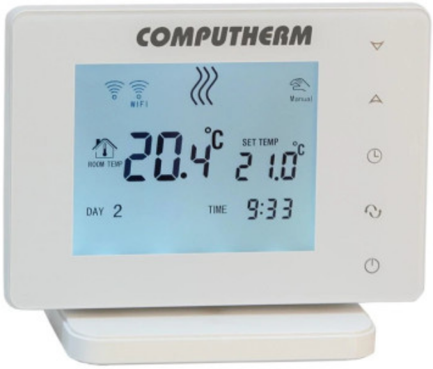
COMPUTHERM E400RF Wi-Fi thermostat is a switching device that can be operated by a smartphone or tablet via Internet, and we especially recommend it for controlling heating or cooling systems. It can be easily connected to any gas boiler having a two-wire thermostat connection point and to any air conditioning apparatus or electrical apparatus, regardless of whether they have a 24 V or 230 V control circuit.
The device consists of two units. One is the thermostat (transmitter unit), the other is the receiver unit that controls the boiler. There is a wireless (radio frequency) connection between the two units, so there is no need to build a wire between the thermostat and the boiler. The two units are factory syncronized. The thermostat and its receiver have their own security code, which guarantees the safe operation of the device. See Chapter 7 for installation, connection and sycronization of the receiver with the thermostat. The thermostat does not transmit continuously, but repeats its current switching command every 5 minutes, and heating/cooling control is provided even after a power failure, if this option is selected in the settings.
The portability of the thermostat offers the following advantages:
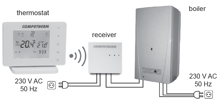
- no need to lay a cable, which is especially advantageous when old buildings are being modernized,
- the optimal location of the device can be selected during operation,
- it is also advantageous when you intend to locate the thermostat in different rooms in the course of the day (e.g. in the living room during the day but in the bedroom at night).
The range of the thermostat-mounted transmitter in open field is approx. 250 m. This distance can be significantly reduced inside a building, especially if a metal structure, reinforced concrete, or adobe wall gets in the way of radio waves. The device can be easily controlled via both Internet and touch button interface, and its operating conditions can be checked continuously. The device also facilitates automatic control on the basis of temperatures and times. Several thermostats that are put into operation at different locations can be registered to the same account and controlled.
COMPUTHERM E400RF Wi-Fi thermostats can be used to control:
- gas boilers
- an existing heating/cooling system remotely
- electric water heaters
- solar systems
- certain groups of other electric devices
With the help of the product the heating/cooling system of your flat, house or holiday home can be made controllable from any place and at any time. This product is especially useful when you do not use your flat or house according to a predefined schedule, you leave your home for an uncertain period of time during the hating season or you intend to use your holiday home during the heating season as well.
The simultaneous use of several COMPUTHERM room thermostats and one COMPUTHERM Q4Z zone controller provides the possibility to e.g. in addition to starting the heater or cooler, a particular thermostat must also control a pump or a zone valve. In this way, it is easy to divide a heating / cooling system into zones, thanks to which the heating / cooling of each room can be controlled separately, thus greatly increasing comfort. Furthermore, the zoning of the heating / cooling system will greatly contribute to the reduction of energy costs, as this will always only heat / cool the rooms where it is required.
IMPORTANT WARNINGS AND SAFETY RECOMMENDATIONS
- Before starting to use the device, please study carefully the instructions for use and follow strictly the instructions therein.
- The thermostat was designed for business or household (not industrial) use, and can be used to control any electric device whose performance does not exceed 2.3 kW (loadability: max. 24 V DC / 250 V AC; 10 A [3 A inductive load]
- Before starting to use the thermostat, make sure that the Wi-Fi network is reliably accessible at the place where you intend to use the apparatus.
- This device has been designed for indoor use. Do not use it in a humid, dusty or chemically aggressive environment.
- This device is a thermostat that can be controlled via a wireless Wi-Fi network. To prevent jamming, keep it away from such electric equipment which may interfere with wireless communications.
- The manufacturer will assume no responsibility for any possible direct or indirect damages or income losses incurring during the use of the device.
- The device will not work without power supply, but the thermostat is able to memorize settings. In case of power failure (outage) it can resume operation without any external intervention after the power supply is restored, provided that this option has been chosen among settings (see Chapter 11). If you intend to use the device in an environment where power outages occur frequently, for safety purposes we propose you to control proper operation of the thermostat regularly.
- Before actually starting to control the device connected to the thermostat, make sure that the device is perfectly functioning when it is controlled by the thermostat and it can be operated reliably.
- The software of the thermostat and the telephone application is constantly upgraded and updated. For proper operation please check regularly whether there is any accessible software or telephone application update, and always use their latest version! Due to constant updates it is possible that some functions of the device and the applications operate and appear in a way other than described in these instructions for use.
- After modifying the desired temperature or any setting on the thermostat by using the touch buttons, the thermostat will send the changed settings to the web server and the receiver after approx. 15 seconds (after the display backlight is turned off).
MEANING OF THE LED LIGHTS ON RECEIVER UNIT
The operating status of the receiver unit is indicated by a green, an orange and a red LED as described below:
- The illuminated green LED indicates that the receiver is properly powered and ready to use.
- The orange LED flashes every second to indicate normal operation of the receiver.
- The illuminated red LED indicates that the output of the receiver is on.
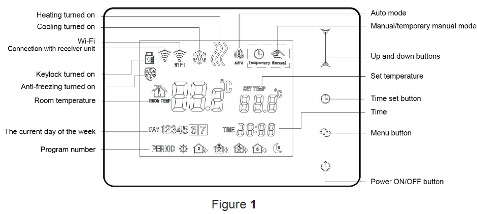
INFORMATION APPEARING ON THE DISPLAY OF THE THERMOSTAT
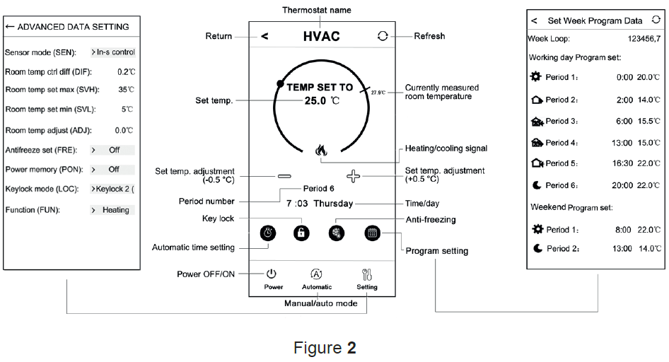
FUNCTIONS ACCESSIBLE IN THE PHONE APPLICATION
LOCATION OF THE THERMOSTAT AND THE RECEIVER UNIT
It is expedient to install the thermostat on the wall of a room used regularly or for a prolonged stay, so that it is located in the direction of natural air movement in the room, but do not expose it to draughts of air or extreme heat effects (e.g. solar radiation, refrigerator or chimney). Its optimal position is at a height of 0.75-1.5 m from the floor level. The receiver of the COMPUTHERM E400RF thermostat should be installed near the boiler, in a place protected from moisture, dust, chemicals and heat. When selecting the location of the receiver, also take it into account that the propagation of radio waves is caused by large metal objects (eg boilers, buffer tanks, etc.) or metal building structures may be adversely affected. If possible, we recommend to install the receiver at a distance of at least 1-2 m from the boiler and other large metal structures, at a height of 1.5-2 m, to ensure interference-free radio frequency communication. We recommend to check the reliability of the radio frequency connection at the selected location before installing the receiver.
ATTENTION: Do not install the receiver under the boiler cover or in the immediate vicinity of hot pipes, as this may damage the components of the appliance and endanger the wireless (radio frequency) connection. To prevent electric shock, entrust a professional to connect the receiver unit to the boiler.
IMPORTANT WARNING: If the radiator valves in your flat are equipped with thermostat head then set the thermostat head to maximum level in the room where you intend to locate the room thermostat or replace the thermostat head of the radiator valve with manual regulating knob, otherwise the thermostat head may disturb the temperature control in the flat.
CONNECTION AND INSTALLATION OF THE THERMOSTAT AND THE RECEIVER UNIT
Attention: Make sure that the COMPUTHERM E400RF thermostat and the apparatus to be controlled are de-energized while putting them into operation. The device should be installed and put into operation by a competent person! If you do not possess the necessary skills and qualifications, please get in touch with an authorized service.
Caution: The modification of the device poses a risk of electric shock or breakdown!
Putting the thermostat into operation
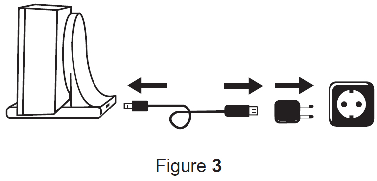
Connect the front of the thermostat to its holder, then connect the USB-C power cable to the back of the holder. Then connect the other end of the USB cable to the adapter included in the package and connect it to the 230 V mains. (Figure 3)
Putting the receiver unit into operation
To put the receiver into operation, snap the front of the receiver unit off the back part using a flat-blade screwdriver. To remove the front panel, press the retaining claws on the top and bottom of the product. After this, the front panel of the receiver should be removed from the back panel and then the back panel should be fixed to the wall near the boiler with the supplied screws. Above the connection points, the N-L and the NO-COM-NC are marked to indicate the connection points.
Connecting the controlled device to the receiver unit
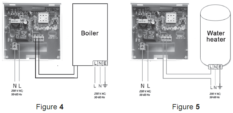
The receiver with changeover output controls the boiler (or air conditioner) via a potential-free relay with connection points: NO, COM and NC. The connection points for the room thermostat of the heating or cooling device to be controlled should be connected to the NO and COM terminals of the terminal that are normaly open (Figure 4). In case the device to be controlled does not have a thermostat connection point, the power supply wire of the device to be controlled must be disconnected and connected to the NO and COM connection points of the thermostat (Figure 5).
Connecting the receiver unit to the mains
The 230 V power supply should be connected to the terminals marked N-L inside the receiver unit with a two-wire cable. It is not necessary to pay attention to the phase correctness when connecting the power supply and it is not necessary to connect a ground because the product is double insulated.
Synchronization of the thermostat and the receiver unit
The two units are syncronized in the factory. The thermostat and its receiver have their own security code, which guarantees the safe operation of the device. If for some reason the thermostat and its receiver unit do not communicate with each other, or if you do not want to use the factory-paired thermostat and receiver together, make the following steps to syncronized the thermostat and the receiver unit:
- Look at the 14 digit identification code on the top of the receiver unit cover or inside the detachable front panel.
- Enable the “Synchronize with Receiver” function in the thermostat asdescribed in Chapter 11.
- Turn off the thermostat, then touch and hold the
 arrow while tapping
  button. Then the
  sign appears on the right side of the display and a two digit number appears on the left. This
 value must match the first 2 digits of the identification code on the receiver unit. If the displayed number and the first two digit numbers of the receiver identification code do not match, use the arrows to change it.
 - Press the menu button on the thermostat. Then the SN2 sign appears onthe right side of the display and a two digit number also appears on the left side. If the displayed number and the third and fourth digits of the receiver identification code do not match, use the arrows to change it.
- Also set
 and
and  in a similar way as above discribed.
 - After setting the appropriate value, touch the menu button. Then the
 sign will appear on the right side of the thermostat display, and a two-digit number will appear on the left side, which is a verification code. If this number does not match with the last two digits of the number sequence on the receiver unit, one of the
  values has been set incorrectly. In this case, start the alignment again and check the set values.
 - If the value displayed on the thermostat matches the last two digits of the number on the receiver, press the
 button again.
 - The thermostat’s display shows the
 text on the right and the number on the left. This funcion may be used in a future development of the product. Do not change this value, just tap to complete the syncronization.
Attention: After a short time when finishing synchronization, the “Synchronize with receiver” function is automatically disabled and remains disabled until it is re-enabled. The thermostat repeats the on/off commands to the receiver unit every 5 minutes.
SETTING UP THE INTERNET CONTROL
Installing the application
The thermostat can be controlled by both a smartphone and a tablet with the help of free application COMPUTHERM E Series. Application COMPUTHERM E Series can be downloaded to iOS and Android operating systems. The applications are accessible through the following link or using a QR code: https://computherm.info/en/wi-fi_thermostats
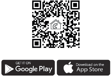
Attention: In addition to English, the application is also available in Hungarian and Romanian languages, and is automatically displayed in the language corresponding to the default settings of the phone (in case of default settings are other than these three languages, it is displayed in English).
Connecting the thermostat to a Wi-Fi network
To be able to control the device remotely, you need to be connected to the Internet via a Wi-Fi network. The already configured COMPUTHERM E400RF can work according to a pre-set program without the need for a permanent Internet connection.
Attention: The thermostat can only be connected to a 2.4 GHz Wi-Fi network.
To complete the synchronization, follow these steps:
- On your phone/tablet switch on Wi-Fi connection. Join the 2.4 GHz Wi-Fi network to be used for the thermostat.
- Activate the positioning (GPS location) feature on your phone.
- Start the COMPUTHERM E Series application.
- Give all the requested access to the application in order for it to work properly.
- Turn off the device by tapping button on the thermostat.
- Touch and hold the
 button for approx. for 10 seconds until the
 symbol on the display flashes quickly.
 - Now touch the “Configure” icon in the right bottom corner in the application.
- On that appears, the name of the Wi-Fi network you want to use is displayed (if not, make sure your phone is connected to that Wi-Fi network, that your phone application has all the necessary permissions, and that the GPS location data is turned on). Enter the network password, then tap the „Connect” icon.
- The connection has been established successfully between the thermostat and the Wi-Fi network when on the display of the thermostat the symbol starts to illuminate continuously.
Connecting the thermostat to the application
- You can search for COMPUTHERM E400RF thermostats connected to the Wi-Fi network concerned by tapping the “Search” icon in the left bottom corner (i.e. this requires that the thermostat is connected to the same Wi-Fi network used for the phone).
- On the appearing page “Search List” you can choose the thermostat you wish to assign to the installed application. Touching the name of the thermostat concerned, it is assigned to the application and from now on the thermostat can be controlled from anywhere. Following this, on the start screen of the application all assigned thermostats appear, together with currently measured (PV) and set (SV) temperatures.
Controlling a thermostat by multiple users
When several users wish to control the same thermostat, after the thermostat has been put into operation the following steps should be carried out to add further users:
- Connect your smartphone/tablet to the Wi-Fi network to which the COMPUTHERM E400RF thermostat has been connected.
- On the apparatus you want to use for controlling download then start application COMPUTHERM E Series.
- Tapping the “Search” icon in the left bottom corner, the phone/table will search COMPUTHERM E Series thermostats connected to the Wi-Fi net work concerned.
- On the appearing “Search List” you can choose the thermostat you wish to assign to the installed application. Touching the name of the thermostat concerned, it will be assigned to the application, and from now on the thermostat can be controlled from anywhere. Following this, on the start screen of the application all assigned thermostats appear, together with currently measured (PV) and set (SV) temperatures.
Attention: If you want to avoid that other users can add your COMPUTHERM E400RF thermostat to their phone applications, you can disable this operation as described in Sub-chapter 10.2.
BASIC OPERATION OF THE THERMOSTAT
When it is switched on, on the basis of the temperature measured by itself and currently set (manually or through programming), the thermostat controls the apparatus(es) (e.g. gas boiler, pump) connected thereto, considering the switch sensitivity of the thermostat (±0.2 °C by factory default). This means that when the temperature is set to 22 °C on the thermostat and then at a switching sensitivity of ± 0.2 °C, the NO and COM connection points of the receiver output relay close at temperatures below 21.8 °C (heating on) and open at temperatures above 22.2 °C (heating off). In cooling mode, the relay switches in the exact opposite direction. The closed status of the NO and COM connection points of the output relay is indicated by the or
or  icon on the device display and in the telephone application according to the selected operating mode.
Attention: Make sure that any settings for the thermostat in the event of a power failure are stored on an external server and it will take a few seconds to update the data on the server. Therefore, if you modify any of the settings of the thermostat (eg operating settings, programming, set temperature, etc.) and then the power supply to the appliance is cut off within a few seconds, the changed settings not be saved.
BASIC SETTINGS
After the application has been started, COMPUTHERM E Series thermostats assigned to the application concerned appear on page “My Thermostat’s”.
Renaming the thermostat assigned to the application
To modify the factory name, tap and hold the thermostat concerned within the application until a pop-up window with the name of “Edit Thermostat” appears. Here you can modify the name of the thermostat within the application by tapping the “Modify current thermostat” icon.
Disabling further connections of the thermostat assigned to the application
If you want to prevent other users from assigning the thermostat to their phone applications then tap and hold the thermostat concerned within the application until a pop-up window with the name of “Edit Thermostat” appears. Tapping the “Lock current thermostat” icon, here you can disable matching the application for other users. Until this function is unlocked the thermostat can only be used by users who have already added the device to their application, and new users will not be able to join the device through the Wi-Fi network.
Attention: When a phone/tablet has already been connected to the Wi-Fi network concerned and application COMPUTHERM E Series has been opened on it then addition of the thermostat to this phone/tablet cannot be disabled with function “Lock current thermostat” any longer.
Deleting the thermostat assigned to the application
If you want to delete the assigned thermostat from the application then tap and hold the thermostat concerned within the application until a pop-up window with the name of “Edit Thermostat” appears. Here you can delete the thermostat from the application by tapping the “Delete current thermostat” icon.
Setting the day and time
- Using phone application:
- To set date and time click on the
 icon in the phone application after the thermostat has been selected. Now the thermostat sets date and time automatically via Internet.
- To set date and time click on the
- On the thermostat:
- While the thermostat is on, tap the button on the thermostat. Then the numbers indicating the hour are flashing on the display. With the help of the buttons set the exact hour then tap the button again. Then the numbers indicating the minute are flashing on the display. With the help of the buttons set the exact minute then tap the button again. Then one of the numbers
 and
and , which indicates the days of the week, will be flashing. With the help of the buttons set the day. By tapping the button again the thermostat will be reset to its initial state.
- While the thermostat is on, tap the
Locking operating buttons
- Using phone application:
- To lock operating buttons tap the
 icon in the phone application after the thermostat has been selected. Henceforward the device cannot be controlled by the touch buttons on the thermostat until the operating buttons are unlocked. To unlock the operating buttons tap the icon again in the phone application.
- To lock operating buttons tap the
- On the thermostat:
- While the thermostat is turned on, tap and hold the button for long (for approx. 10 seconds) until the icon appears on the display of the thermostat. Henceforward the device cannot be controlled by the touch buttons on the thermostat until the operating buttons are unlocked. To unlock the operating buttons tap and hold the icon for long (for approx. 10 seconds) until the icon disappears on the display of the thermostat.
- While the thermostat is turned on, tap and hold the
For the operation of the thermostat some functions can be set. Operation-related settings can be performed in the following way:
- Using phone application:
- Tap the
 icon in the right bottom corner. The settings menu of thermostat, where you can modify the settings, will appear.
- Tap the
- On the thermostat:
- Turn off the device by tapping the button.
- Tap and hold the button and at the same time, touch the button for a short time.
- Now the thermostat enters the settings menu:
 will appear on the rightside of the center of the screen and
  will appear instead of the set temperature.
 - Tapping the button you can switch between the functions to be set.
- A given function can be set by arrows.
- To exit the settings menu and save the settings:
- switch the appliance off and on again using the button, or
- wait 15 seconds until the thermostat display returns to the main screen, or
- scroll through the settings by pressing the button.
- switch the appliance off and on again using the
- Turn off the device by tapping the
The setting options are shown in the table below:
| Display | Function | Setting Options | Default Setting | Detailed Description |
| DIF | Selecting switching sensitivity | 0.1 – 1.0 °C | 0.2 °C | Chapter 11.1 |
|
SVH |
Defining maximum settable temperature |
5 – 99 °C |
35 °C |
—- |
|
SVL |
Defining minimum settable temperature |
5 – 99 °C |
5 °C |
—- |
|
ADJ |
Calibration of the temperature sensor |
-3 – +3 °C |
0 °C |
Chapter 11.2 |
|
FRE |
Antifreezing |
00: OFF |
00 |
Chapter 11.3 |
| 01: ON | ||||
|
PON |
Memorizing ON/OFF status in case of a power failture | 00: OFF |
01 |
Chapter 11.4 |
| 01: ON | ||||
|
LOC |
Setting the keylock funcion |
01: only On/Off button works 02: all buttons locked |
02 |
—- |
|
FUN |
Changing between heating or cooling mode | 00: heating
01: cooling |
00 |
Chapter 11.5. |
|
SNP |
Synchronization with a receiver unit |
00: disable synchronization
01: enable synchronization |
00 |
Chapter 7.3. |
|
FAC |
Resetting to factory default |
00: Resetting to factory default 08: Saving settings |
08 |
Chapter 11.6 |
Selecting the switching sensitivity (DIF)
It is possible to set the switching sensitivity. By setting this value, you can specify how much the appliance switches the connected device on/off below/above the set temperature. The lower this value, the more uniform the internal temperature of the room, the greater the comfort will be. The switching sensitivity does not affect the heat loss of the room (building).
In case of higher comfort requirements, the switching sensitivity should be chosen so as to ensure the most constant internal temperature. However, also make sure that the boiler is switched on several times hourly only at low outdoor temperatures (eg -10 °C), as frequent switching off and on will impair the efficiency of the boiler’s operation and increase gas consumption. The switching sensitivity can be set between ±0.1 °C and ±1.0 °C (in 0.1 °C increments). Except some special cases, we recommend setting ±0.1 °C or ± 0.2 °C (factory default setting). See Chapter 9 for more information on switching sensitivity.
Calibration of the temperature sensor (ADJ)
The measuring accuracy of the thermometer of the thermostat is ± 0.5 °C. The temperature displayed by the thermostat can be modified in 0.1 °C increments in comparison to the temperature measured by the temperature sensor, but the modification can not exceed ± 3 °C.
Antifreezing (FRE)
When the antifreezing function of the thermostat is activated, the thermostat will switch on its output, regardless of any other setting, when the temperature measured by the thermostat goes below 5 °C. When the temperature reaches 7 °C, normal operation of the output is restored (according to the set temperature).
Memorizing ON/OFF status in case of a power failture (PON)
By means of the Memorizing Settings function of the thermostat you can select the mode in which the thermostat continues to operate:
- 00/OFF: the thermostat turns off and remains turned off until this mode is altered, regardless whether the thermostat was on or off before the power failure.
- 01/ON: the thermostat returns to the same state in which it was before the power failure (default setting).
Changing between heating or cooling mode (FUN)
You can easily switch between heating (00; factory default) and cooling (01) modes.
The connection points NO and COM of the thermostat’s output relay close at a temperatures below the set temperature in heating mode and at temperatures above the set temperature in cooling mode (taking the set switching sensitivity into account).
Restoring default setting (FAC)
All settings of the thermostat, except for date and time, will be restored to factory setting. To restore factory setting, after selecting  setting option and tapping the button several times, switch over the appearing
  setting to 00. Then tap the button once to restore factory setting. If you move on by tapping the button and leaving the value at its default value () then the device will not return to default setting but save the settings and exits the operation-related settings menu.
SWITCHING BETWEEN ON AND OFF POSITIONS
SWITCHING BETWEEN ON AND OFF POSITIONS AND MODES OF THE DEVICE
- The thermostat has the following 2 positions:
- Off position
- On position
- You can switch between off and on positions in the following way:
- Using phone application: by tapping the icon
- On the thermostat: tapping the button
- Using phone application: by tapping the
When the thermostat is off, the screen of the devices turns off and in the application POWER-OFF lettering replaces measured and set temperatures, and the relay outputs of the device go into off (open) position. When the thermostat is on, the display of the device illuminates continuously. If you touch the touch buttons or modify the settings of the thermostat with the phone application, the light intensity on the thermostat gets higher for approx. 10 seconds then falls back to basic level.
When the thermostat is on, it possesses the following 2 modes of operation:
- Manual mode
- Programmed auto mode
You can switch between the modes in the following way:
- Using phone application: by touching
 or
or icons
icons - On the thermostat: touching the button
The currently selected mode is indicated as follows:
- In the phone application: manual mode by the icon and programmed auto mode by the icon
- On the thermostat: manual mode by the
 icon programmed auto mode by one of the following icons
 (according to the current switching scheme) and by the
 icon. The two modes are described in detail in the following sub-chapters.
Manual mode
In manual mode the thermostat maintains a preset temperature until the next intervention. If the room temperature is lower than that set on the thermostat, the output of the thermostat will switch on. If the room temperature is higher than that set on the thermostat, the output of the thermostat will switch off. The temperature to be maintained by the thermostat can be specified in 0.5 °C steps (the minimum and maximum values of the adjustable range are 5 °C and 99 °C, respectively).
The currently set temperature can be modified in the following way:
- Using phone application:
- with the
 icons
icons - moving the slide (groove) on the circular scale
- with the
- On the thermostat: with the buttons
Programmed auto mode
Description of the programmed mode
Programming means setting of switching times and selection of corresponding temperature values. Any temperature set for a switch will remain in effect until the time of the next switch. Switching times can be specified with an accuracy of 1 minute. Within the temperature range (the minimum and maximum values of the adjustable range are 5 °C and 99 °C, respectively) specified in the settings a different temperature can be chosen for each switching time, in 0.5 °C increments. The device can be programmed for a period of one week. In the programmed auto mode the thermostat operates automatically, and cyclically repeats the entered switches every 7 days. The following 3 options are available to program the thermostat:
- 5+2 mode: setting 6 switches per day for 5 working days and 2 switches per day for 2 days of the weekend
- 6+1 mode: setting 6 switches per day from Monday till Saturday and 2 switches on Sunday
- 7+0 mode: setting 6 switches per day for every day of the week
If you do not need all adjustable switches on certain days (e.g. only 4 switches is required on working days), you can eliminate unnecessary switches by setting their time and temperature to the time and temperature of the last switch you want to use.
Description of the steps of programming
Using phone application
- To enter programming mode touch the
 icon. Then the screen for programming appears on the display.
 - The indication of the currently selected programming mode is located at the top of the screen for programming, beside the legend Programing mode. Touching this, you can switch between programming modes as follows:
- 12345,67: 5+2 mode
- 123456,7: 6+1 mode
- 1234567: 7+0 mode
- Switches belonging to a given programming mode are below the indication of the programming mode. You can modify data (time, temperature) of switches by tapping the value concerned.
- To complete programming and return to the screen belonging to the thermostat touch the < icon in the upper left corner. Programs that were set earlier can be checked at any time by entering the programming mode again.
On the thermostat
- To enter programming mode touch the button for approximately 5 seconds. Then on the display the legend LOOP appears in place of the hour, and the indication belonging to the currently selected programming mode replaces the current day.
- With the buttons choose the preferred programming mode as follows:
- for 5+2 mode: 12345
- for 6+1 mode: 123456
- for 7+0 mode: 1234567
- Now touch the button again.
- Following this, you can specify or modify various switch times and temperatures as follows:
- You can switch between switch times with the button.
- With the help of you can switch between data belonging to switch times (temperature, hour value of the time, minute value of the time).
- Values are always set by buttons. After the program of weekdays has been set, you can set the program of the days of the weekend. The day and switch being set are shown by the icon flashing on the display.
- You can switch between switch times with the
- Programs that were set earlier can be checked at any time by repeating the steps of programming mode.
Attention: In the interest of logical programming ensure that in programming the times of successive switches succeed each other during the course of the day, i.e. you should specify switches in chronological order.
Modifying temperature until the next switch in the program
If the thermostat is in programmed mode, but you want to temporarily change the set temperature until the next program switch, you can do so as follows:
- Using the phone application: using the icons or moving the slide (groove) on the circular scale, the icon will appear in the application instead of the icon.
- On the thermostat: using the buttons. The thermostat’s display will show
 and at the same time. The set temperature this way will remain in effect until the next program switch.
The „Modify temperature until the next switch in the program” mode is marked as follows:
- In the phone application: with the icon
- On the thermostat: with the and icons
PRACTICAL ADVICES, TACKLING ANY PROBLEMS THAT MAY OCCUR
Problem with the Wi-Fi connection
When the product cannot be connected to a Wi-Fi network or cannot be controlled via the Internet because the connection between the product and the Internet interface is lost and the application indicates that the device is not available, we recommend that to check the list of Frequently Asked Questions (FAQs) collected on our website and follow the steps described there.
Use of the application
The phone/tablet application is under continuous improvement. We propose to update the application to the latest version because user experience is improved continuously and new functions are accessible in the updated versions.
FREQUENTLY ASKED QUESTIONS
When you think that your appliance is operating incorrectly or encounter any problem while the appliance is being used then we recommend that you read Frequently Asked Questions (FAQ) available on our website, where we collected the problems and questions that most frequently occur while our appliances are being used, along with the solutions thereto: http://www.computherm.info/en/faq

The vast majority of the problems encountered can be solved easily by using the hints available on our website, without seeking professional help. If you have not found a solution to you problem, please pay a visit to our qualified service.
Warning: The manufacturer does not assume responsibility for any direct or indirect damages and loss of income occurring while the appliance is being used.
TECHNICAL DATA
- Trademark: COMPUTHERM
- Model identifier: E400RF
- Temperature control class: Class I
- Contribution to the efficiency of seasonal space heating: 1 %
- Temperature measuring range: 0 °C – 50 °C (in 0.1 °C increments)
- Temperature measurement accuracy: ±0,5 °C
- Adjustable measuring range: 5 °C – 99 °C (in 0.5 °C increments)
- Switch sensitivity: ±0.1 °C – ±1.0 °C (in 0.1 °C increments)
- Temperature calibration range: ±3 °C (in 0.1 °C increments)
- Supply voltage: USB-C 5 V DC, 1 A
- Operating frequency: RF 433 MHz, Wi-Fi (b/g/n) 2.4 GHz
- Transmission distance: approx. 250 m in open terrain
- Storage temperature: -5 °C … +55 °C
- Operating relative humidity: 5 % – 95 % without condensation
- Protection against environmental impacts: IP30
- Standby power consumption: Max. 0.1 W
- Dimensions: 130 x 23 x 92 mm with the holder (W x H x D)
- Weight: 156 g thermostat + 123 g holder
- Type of the temperature sensor: NTC 3950 K 10 kΩ 25 °C
Technical data of the reciver unit
- Power supply voltage: 230 V AC, 50 Hz
- Switchable voltage: Max. 24 V DC / 250 V AC
- Switchable current: 10 A (3 A inductive load)
- Operating frequency: 433 MHz
- Storage temperature: -5 °C … +55 °C
- Operating relative humidity: 5 % – 95 % without condensation
- Protection against environmental impacts: IP30
- Standby power consumption: Max. 0.3 W
- Dimensions: 86 x 86 x 29 mm (W x H x D)
- Weight: 98 g
The COMPUTHERM E400RF type Wi-Fi thermostat complies with directives RED 2014/53/EU and RoHS 2011/65/EU


Manufacturer
- Manufacturer: QUANTRAX Ltd.
- H-6726 Szeged, Fülemüle u. 34.
- Telephone: +36 62 424 133
- Fax: +36 62 424 672
- E-mail: [email protected]
- Web: www.quantrax.hu
- www.computherm.info
- Country of origin: China

Copyright © 2021 Quantrax Ltd. All rights reserved.
Reference
Download Manual:
COMPUTHERM E400RF Wi-Fi Thermostat Instruction Manual