
Bryant SYSTXZNSMS01 Smart Sensor Thermostats

Installation Instructions
NOTE: Read the entire instruction manual before starting the installation.
Safety Considerations
Improper installation, adjustment, alteration, service, maintenance, or use can cause an explosion, fire, electrical shock, or other conditions which may cause death, personal injury or property damage. Consult a qualified installer, service agency or your distributor or branch for information or assistance. The qualified installer or agency must use factory-authorized kits or accessories when modifying this product. Refer to the individual instructions packaged with the kits or accessories when installing. Follow all safety codes. Wear safety glasses, protective clothing, and work gloves. Have a fire extinguisher available. Read these instructions thoroughly and follow all warnings and cautions included in the literature and attached to the unit. Consult local building codes and the current edition of the National Electrical Code (NEC) NFPA 70. In Canada, refer to the current editions of the Canadian Electrical Code CSA C22.1. Recognize safety information. When you see this symbol on the unit and in instructions or manuals, be alert to the potential for personal injury. Understand the signal words DANGER, WARNING, and CAUTION. These words are used with the safety alert symbol. DANGER identifies the most serious hazards, which will result in severe personal injury or death. WARNING signifies hazards, which could result in personal injury or death. CAUTION is used to identify unsafe practices, which may result in minor personal injury or product and property damage. NOTE is used to highlight suggestions that will result in enhanced installation, reliability, or operation.
Introductions
Smart Sensors are optional replacements for Remote Room Sensors used with communicating Zoning systems (see equipment Product Data Sheet for compatibility with this Smart Sensor). It provides a temperature display on a touch screen to adjust the desired temperature within the zone. It also displays outdoor temperature and indoor humidity. When used with a Communicating System Control – FAN, HOLD and HOLD UNTIL features are available.
Installation Considerations
Any zone may use a Smart Sensor. The Smart Sensor can be “home run” wired directly to the Damper Control Module, or “daisy chained” from the wall control or another Smart Sensor via a 4-wire ABCD communication bus. Ordinary thermostat wire is recommended; however, solid conductor, stranded, or shielded wire may be used. Use 22 AWG or larger for normal wiring applications. Continuous wire lengths over 100 ft. should use 20 AWG or larger. Plan the connection of each Smart Sensor to provide the easiest wiring route.
NOTE: Whenever possible, it is suggested to always “home run” wires back to the Damper Control Module for convenience of troubleshooting. Using a “pig-tailed” connection, or a field-supplied terminal block may be helpful in achieving proper wire termination at the Damper Control Module.
A Smart Sensor may now be used to control Zone 1. In addition, a Remote Room Sensor may also be used in the same zone. If a Remote Room Sensor is applied in the same zone, the Remote Room Sensor has
temperature priority over the Smart Sensor.

Step 1 – Select Smart Sensor Location
The sensor should be mounted:
- Approximately 5 ft. (1.5m) from floor.
- Close to center of zone, preferably on the inside partitioning wall.
- On section of wall without pipes or ductwork.
- Where wiring can be routed to it within wall. Avoid running directly next to other AC power.
Sensor should NOT be mounted: - Close to a window, on outside wall, or next to a door leading to the outside.
- Exposed to direct light and heat from a lamp, sun, fireplace, or another temperature-radiating object which may cause a false reading.
- Close to or in direct airflow from supply registers and return-air grilles.
- In areas with poor air circulation, such as behind a door or in an alcove.
- Do not run wires next to AC power lines.
Step 2 – Install Smart Sensor
WARNING
ELECTRICAL SHOCK HAZARD
Failure to follow this warning could result in personal injury or death. Before installing sensor, turn off all power to unit. There may be more than 1 power disconnect.
- Turn OFF all power to unit.
- If an existing thermostat or sensor is being replaced:
- Remove existing device from wall.
- Disconnect wires from existing device, 1 at a time. Be careful not to allow wires to fall back into wall.
- Discard or recycle old device.
- If 4 wires exist in wall, they may be used. If not, plan and route wiring to connect with either the Damper Control Module, or User Interface. Multiple Smart Sensors may be daisy chained together, but somewhere chain must connect to either Damper Control Module or the Communicating wall control. (Smart Sensor daisy chain wire limit is 100 ft.)
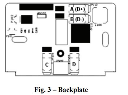
Recommended connection is:- A – Green = Data A
- B – Yellow = Data B
- C – White = 24vac (com)
- D – Red = 24vac (hot)
NOTE: It is not mandatory that the above color code be used, but each ABCD connection in the system MUST be wired consistently.
- To mount Smart Sensor, remove rear mounting base. Route wires through hole in mounting base and level base against wall.
- Mark wall through 2 mounting holes and drill two 3/16-in. holes. Secure assembly to wall with 2 anchors and screws provided, making sure all wires properly extend through opening.
- Adjust length and routing of thermostat wire to reach each terminal entry on the connector. Strip 1/4-in. of insulation from each wire and properly connect to A-B-C-D.
- Push any excess wire into the wall. Seal hole in wall to prevent any air leaks. Leaks can affect Smart Sensor operation.
- Attach Smart Sensor to the mounting base by lining up the plastic guides and gently snapping assembly together.
CAUTION
ELECTRICAL OPERATION HAZARD
Failure to follow this caution may result in equipment damage or improper operation. Improper wiring or installation may damage the Smart Sensor. Check to make sure wiring is correct before proceeding with installation or turning on unit
Step 3 – Setup and Checkout
Smart Sensor Setup
After successful communications with the Master Thermostat has occurred, the screen shall change to the Home Screen. However, if the Zone Address has never been set, the Enter Zone Address Screen is displayed instead with an initial zone number of 2.
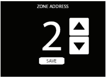
Use the up/down buttons to select the correct zone address number 1 through 8. If only one Damper Control Module exists, the zone address selection will only be 1 through 4. Once the zone number is selected, press the save button to store the zone address and exit the setup menu.
The Smart Sensor is ready to operate.
- Backlighting
The screen backlighting will energize whenever a button is pressed. The backlighting will de-energize after 5 – 30 (default 15) seconds of no push button activity (selectable from the Settings button after pressing the menu button). To access the backlighting screen touch Menu from the main screen, then backlight button. Backlight Screen is used to set the backlight intensity in Active and Dormant backlight modes. The blue Active Backlight Wheel is used to adjust the backlight intensity when the thermostat is in an active state. The purple Dormant Backlight Wheel is used to adjust backlight intensity when the thermostat is in a dormant state (not being viewed or adjusted by the end user). Adjustment is made by placing a finger on the wheel and dragging the wheel up or down. Alternatively a tap at the top of the wheel or the bottom of the wheel shall adjust the setpoint by one number. - Fan Mode
Swiping left to right from the main screen will show the fan mode screen. The “Fan Screen” is used to allow you to select the fan mode for this thermostats zone. Pressing one of the Left Arrow Button or Right Arrow Button shall scroll through the fan modes of AUTO or OFF, LOW, MED and HIGH. AUTO model will operate the fan only when the system is heating or cooling that zone. LOW, MED and HIGH modes will run continuously at that speed until you switch the zone back to AUTO Fan Mode. - Changing Zone Address
To change an existing zone address, enter the setup menu by swiping from Left to Right on the Home Screen to display the Fan Screen, pressing and holding the Fan button for 6 seconds, and then pressing on the Zone Address Line. Use the up/down buttons to select the correct zone address and then press “Done” and exit the setup menu. If no buttons are pressed for approximately 30 minutes, the screen will automatically save and exit back to a normal display. To ensure that all changes are recognized by the main control, perform the “Full Installation” function in the Installation & Service Menu of the Touch Control after zone addresses are changed. - Temperature Up/Down Arrows
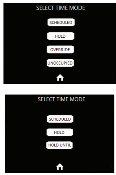
Use the TEMP up/down arrows to change a zone temperature setpoint. The “HEAT TO” or the “COOL TO” setpoints will increment or decrement accordingly. If not in a “HOLD” mode, changing the setpoint, when used with the User Interface wall control, will cause the Override timer to be displayed (i.e. 2-hours). If used with the main System Control, changing the setpoint will cause a HOLD UNTIL/OVERRIDE with a default time of approximately 3 hours from the current time to be displayed. Pressing the HOLD UNTIL/OVERRIDE button displays the Select the Time Mode Screen that allows the Override type to be changed to SCHEDULED (no override), HOLD, UNOCCUPIED (when used with the User Interface wall control only), or to keep it a HOLD UNTIL/OVERRIDE. - Hold Until Time Screen
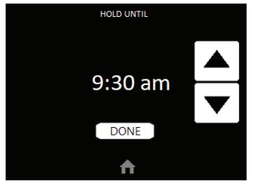
Pressing the OVERRIDE (when used with the User Interface wall control only), or HOLD UNTIL (when used with the main System Control) button will display the Override Timer screen. When used with either wall control, the Override timer or default time can be increased or decreased by using the up/down buttons. The buttons can be used to raise or lower the Override timer or the default time in 15-minute increments up to a maximum of 24 hours. Pressing the DONE button will return back to the HOME screen.
NOTE: If the wall control is configured for non-programmable operation, the Smart Sensor will ignore HOLD and Override functions at the Smart Sensor. - Select Time Mode Screen
Pressing the HOLD, HOLD UNTIL/OVERRIDE, SCHEDULED, or OCCUPIED (when used with the User Interface wall control only) (when shown in the middle of the main screen) button will cause the Override Type screen to be displayed. Pressing the HOLD button will cause the system to use the active (displayed) temperature setpoints indefinitely. Pressing the SCHEDULED button cancels any type of override and the system resumes normal programming schedules. When used with the User Interface wall control, pressing the UNOCCUPIED button will cause “UNOCCUPIED” to be displayed and the unoccupied temperature settings will be displayed.
NOTE: The communication System Control does not include an “unoccupied” mode. - System Off
When the OFF mode is selected on the Main System Control the Smart Sensor will show “SYSTEM OFF” in the middle of the display screen. The end user will be unable to operate the system from the Smart Sensor.
Keypad Lock
The Smart Sensor can be locked by going to the menu from the main screen, then lockout. Lockout is used to prevent unauthorized changes via the touch screen interface. All touch interaction is locked out until the proper unlock code is entered. After 5 failed attempts at unlocking the thermostat, more attempts shall not be allowed for a 5 minute period. - Vacation
When Vacation Mode gets set from the Master Thermostat and this state transfers to the Smart Sensor, VACATION will be displayed below the indoor temperature and the Heat and Cool Setpoints and Fan State shall change to the vacation settings. A lock icon shall appear to the right of the VACATION text for 15 minutes and the up/down buttons shall beremoved. After the 15 minutes elapses, the up/down buttons shall appear again and an override of the vacation setpoints will be allowed. The middle of the screen shall display Vacation when active. - Error Display
The middle of the screen shall display the following errors when they occur. COM ERROR (Communication Error) will be displayed if the Smart Sensor cannot send or receive communication data with the Communicating System Control. Check ABCD wiring and Zone address.
SYST ERROR (System Error or Malfunction) will be displayed if a system critical error is active at the Communicating System Control. Check fault history at the wall control. TEMP ERROR (temperature reading error) will be displayed if the Smart Sensor cannot receive a reading from the on-board sensor.
Smart Sensor Operation
The Smart Sensor allows control and changing of zone temperature setpoints. Continuous FAN selection is available; AUTO, LOW, MED, HIGH. Other features include the scrolling banner showing Outdoor Temperature and Indoor Relative Humidity. Smart Sensor Functions also include; HOLD and UNOCCUPIED settings.
Changing Desired Temperature

- The current zone temperature will be displayed on the screen.
- Press the up/down arrows for HEAT TO or COOL TO to change the setpoints.
- The default time for temporarily overriding the temperature schedule is 2:00 HRS as indicated by the text in the lower center of the screen.
- Pressing the OVERRIDE (User Interface wall control) / HOLD UNTIL (main System control) button displays the Select Time Mode Screen where the type of Override can be changed to HOLD (permanent length of time), OVERRIDE/HOLD UNTIL (specified time length), SCHEDULED (removes any override), or UNOCCUPIED (User Interface wall control only).
- Temporary override time can be changed in 15-minute increments by pressing the OVERRIDE or HOLD UNTIL button to increase or decrease the override timer.

NOTE: Override will not appear if programming has been turned off.
Continuous Fan Adjustment
- From the main screen swipe right to left to get to the fan menu screen.You will be able to scroll through the following: AUTO, LOW, MED, HIGH.
- When AUTO is selected, zone airflow is available only when a heating or cooling demand exists within the zone.
- When LOW, MED, or HIGH is selected, zone airflow will be continuous without a heating or cooling demand.

Outdoor Temperature and Indoor Relative Humidity
The top area of the screen is used to display the Banner. The Banner is used to provide status information to the end user of the thermostat. The Banner scrolls through several pieces of information, changing every 3 seconds. These pieces of information include Outdoor Temperature, Date and Time, Fan Status, Mode and Humidity.

REFERENCE
Download Manual
Bryant SYSTXZNSMS01 Smart Sensor Thermostats Installation Instruction
Bryant SYSTXZNSMS01 Smart Sensor Thermostats Installation Instruction