Braeburn 1030 Non-Programmable Thermostat
Warning For installation by experienced service technicians only.
Caution Possible electric shock or damage to equipment can occur. Disconnect power before beginning the installation
This thermostat requires 24 Volt AC Power or 2 properly installed “AA” Alkaline batteries for proper operation. When connecting 24 Volt AC Power, the batteries may be installed as a backup. For use only as described in this manual. Any other use will void the warranty This manual is for Installer use only – do not leave it with the end user.
SPECIFICATIONS
This thermostat is compatible with:
- Single-stage conventional and heat pump systems
- Single-stage heat pumps with auxiliary heat
- 250 – 750 millivolt heating-only systems
- 2 wire hydronic zone systems
Electrical and Control Specifications
- Electrical Rating: 24 Volt AC
- 1 amp maximum load per terminal
- AC Power: 18 – 30 Volts AC
- DC Power: 3.0 Volt DC (2 “AA” Alkaline Batteries Included)
- Control Range: 45° to 90° F (7° to 32° C)
- Temperature Accuracy: +/- 1° F (+/- .5° C)
Terminations
- 1030: Rc, Rh, W1, Y1, G, O, B, C
- 1230: Rc, Rh, W1/E, W2, Y1, G, O, B, L, C
INSTALLATION
Warning Disconnect power before beginning installation.
Thermostat Location
Install the thermostat approximately 5 feet (1.5m) above the floor in an area that has a good amount of air circulation and maintains an average room temperature. Avoid installation in locations where the thermostat can be affected by drafts, dead air spots, hot or cold air ducts, sunlight, appliances, concealed pipes, chimneys, and outside walls

Install the Sub-Base
- Remove the sub-base from the body of the thermostat.
- Mount the sub-base as shown below

INSTALLATION
Provide Power

- Battery Power – Insert the 2 supplied “AA” type alkaline batteries into the battery compartment located in the rear housing of the thermostat. Make sure to position the Positive (+) and Negative (-) sides of the batteries correctly with the +/- symbols in the battery compartment.
- Optional 24 Volt AC power – Connect the common side of the transformer to the C terminal on the thermostat sub-base. In dual transformer installations, the transformer common must come from the
cooling transformer
Set Installer Switches
The Installer switches are located on the back of the thermostat and must be properly configured for this thermostat to operate properly.

Attach to Thermostat Sub-Base

Once you complete the wiring in Section 3, attach the thermostat to the sub-base and then configure the Installer Settings in Section 5.
- Line up the thermostat body with the sub-base.
- Carefully push the thermostat body against the sub-base until it snaps in place.
NOTE: This thermostat ships configured as a conventional (CONV) thermostat.
WIRING
Conventional and Heat Pump Systems – Typical Wiring Configurations
| NOTE: Make sure installer system selection
switch is properly set to CONV or HP. See Section 2. |
CONVENTIONAL | HEAT PUMP | ||||
| 1030 / 1230 | 1230 | 1030 / 1230 | 1230 | |||
| Wiring Terminal | Terminal Description | Heat Only or Millivolt | 1 Heat/
1 Cool |
2 Heat/
1 Cool |
1 Heat/
1 Cool |
2 Heat/1 Cool (w/Aux Heat) |
| Rh | 24 VAC Heating Transformer | Rh | Rh1 | Rh1 | Rh6 | Rh6 |
| Rc | 24 VAC Cooling Transformer | – | Rc1,2 | Rc1,2 | – | – |
| W1/E | (W1) Conventional Heat Relay (E*) Emergency Heat Relay | W1 | W1 | W1 | – | E7 |
| W2* | 2nd Stage Heat/Auxiliary Heat | – | – | W2 | – | W27 |
| Y1 | Compressor Relay | – | Y1 | Y1 | Y1 | Y1 |
| G | Fan Relay | G3 | G | G | G | G |
| O | Cool Active Reversing Valve | – | – | – | O8 | O8 |
| B | Heat Active Reversing Valve | – | – | – | B8 | B8 |
| L* | System Malfunction Indicator | – | – | – | L9 | L9 |
| C | 24 VAC Transformer Common | C4 | C4,5 | C4,5 | C10 | C10 |
NOTES – Conventional Systems
- Remove factory-installed jumper wire for dual transformer systems
- Only required for dual transformer systems
- Only connect if needed for the system
- Optional 24 VAC transformer common connection
- For dual transformer systems, common must come from the cooling transformer Provide disconnect and overload protection as required.
NOTES – Heat Pump Systems - Do not remove factory installed jumper wire
- If no separate emergency heat relay, connect to W2 and Install a field-supplied jumper wire from W2 to E 8 Wire O for the cool active valve or B for the heat active valve (never both)
- If using the optional L terminal, the 24 VAC common must be connected (C terminal)
- Optional 24 VAC transformer common connection Provide disconnect and overload protection as required.
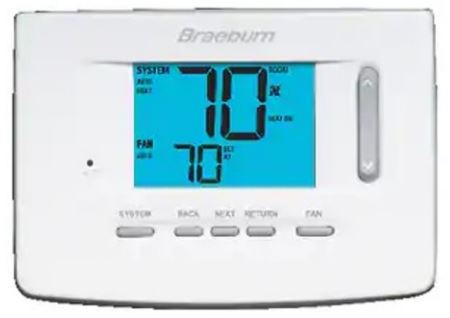
QUICK REFERENCE

Thermostat and Display
- SYSTEM Switch…………………..Selects the system you want to control
- FAN Switch…………………………Selects the system fan mode
- Up / Down Arrow Buttons…….Increases or decreases settings
- MENU Button………………………Used to access thermostat User / Installer setting modes
- Room Temperature ………….. Displays the current room temperature
- Set Temperature ……………… Displays the current setpoint temperature
- System Mode ………………….. Displays the system mode and current system status
- Fan Mode Indicator …………. Indicates the current system fan mode
- Fan Status Indicator ………… This indicates that the system fan is running
- Low Battery Indicator ……… Indicates when the batteries need to be replaced
- Battery Compartment………….Located on the back side of the thermostat
INSTALLER SETTINGS
The Installer Settings must be properly configured in order for this thermostat to operate correctly. The Installer Settings are menu driven. The portion of these settings that do not apply to your setup will be skipped.

- To Enter Installer Settings Menu
- Press and hold down the MENU button for 5 seconds. 2 Release the MENU button after the first installer setting is displayed.
- Change settings as required using the or buttons.
- Press MENU to move to the next setting.
- The menu will exit automatically after the last setting. *If 0000 IL is displayed, you must enter your 4-digit installer lock code to proceed (see Installer Settings 9 and 10).
| No. | Installer Setting | Displayed | Default Setting | Available Settings | Description of Available Settings |
| 1 | Temperature Scale | DEG | F | F | Select for Fahrenheit temperature display |
| C | Select for Celsius temperature display | ||||
| Selects a temperature scale of either °F or °C. | |||||
| 2 | 1st Stage Differential | DIF1 | 0.5 | 0.5, 1.0, 2.0 | Select a 1st stage temperature differential of 0.5°, 1° or 2° F (0.2°, 0.5° or 1.0° C) |
| Selects a 1st stage temperature differential which controls the degree of separation between the setpoint temperature and the 1st stage of heating or cooling. | |||||
| 3 | 2nd Stage Differential | DIF2 | 2.0 | 1.0, 2.0, 3.0
4.0, 5.0, 6.0 |
Select a 2nd stage temperature differential of 1°, 2°, 3°, 4°, 5° or 6° F (0.5°, 1.0°, 1.5°, 2.0°,
2.5° or 3.0° C) |
| [1230 only] Selects a 2nd stage temperature differential which controls the degree of separation between the 1st and 2nd stage of heating or cooling. | |||||
| 4 | Compressor Short Cycle Protection (CSCP) | CSCP | 5 | 5, 4, 3,
2, 1, 0 |
Select CSCP delay duration in minutes |
| Selects the number of minutes the compressor will be locked out after turning off. This delay will run simultaneously with any delay built into the equipment. | |||||
| 5 | Heat Setpoint Upper Limit | HIGH HEAT | 90 | 90 – 45
(32˚ to 7˚C) |
Select a Heat Setpoint Upper Limit of 90° to 45°F (32° to 7°C) |
| Selects the upper setpoint adjustment limit that cannot be exceeded in heat mode. | |||||
| 6 | Heat Setpoint Lower Limit | LOW HEAT | 45 | 45 – 90
(7˚ to 32˚C) |
Select a Heat Setpoint Lower Limit of 45° to 90°F (7° to 32°C) |
| Selects the lower setpoint adjustment limit that cannot be exceeded in heat mode. | |||||
| 7 | Cool Setpoint Lower Limit | LOW COOL | 45 | 45 – 90
(7˚ to 32˚C) |
Select a Cool Setpoint Lower Limit of 45° to 90°F (7° to 32°C) |
| Selects the lower setpoint adjustment limit that cannot be exceeded in cool mode. | |||||
| No. | Installer Setting | Displayed | Default Setting | Available Settings | Description of Available Settings |
| 8 | Cool Setpoint Upper Limit | HIGH COOL | 90 | 90 – 45
(32˚ to 7˚C) |
Select a Cool Setpoint Upper Limit of 90° to 45°F (32° to 7°C) |
| Selects the upper setpoint adjustment limit that cannot be exceeded in cool mode. | |||||
| 9 | Installer Lock | INST | NO | NO | Installer Lock disabled |
| Y | Installer Lock enabled | ||||
| When enabled, a 4-digit lock code can be entered in setting 10. This lock code will be required the next time the Installer Settings menu is accessed. Select NO to skip the installer lock. | |||||
| 10 | Installer Lock Code | IL | 0000 | 0-9 | Select 0-9 for each digit |
| [Only available if Installer Lock was enabled in setting 9] Select a 4-digit lock code (0-9 for each digit) to lock the Installer Settings menu. The code 0000 is not a valid lock code and cannot be used. | |||||
| 11 | Installer Clear (factory reset) | CLR | NO | NO | Clear disabled – No changes made |
| Y | Clear enabled – Factory Reset | ||||
| Selecting Y (YES) will return thermostat to all factory default settings. Factory reset will take affect upon exiting Installer settings menu. | |||||
Additional options are located in the User Settings – See User Manual.
SYSTEM TESTING
Warning Read Before Testing
- Do not short (or jumper) across terminals on the gas valve or at the heating or cooling system control board to test the thermostat installation. This could damage the thermostat and void the warranty.
- Do not select the COOL mode of operation if the outside temperature is below 50º F (10º C). This could possibly damage the controlled cooling system and may cause personal injury.
- This thermostat includes an automatic compressor protection feature to avoid potential damage to the compressor from short cycling. When testing the system, make sure to take this delay into account.
NOTE: The compressor delay can be bypassed by adjusting Installer Setting 4 – See section 5.
- Move the SYSTEM switch to HEAT mode.
Press the button to raise the set temperature a minimum of 3 degrees above the current room temperature. The system should start within a few seconds. With a gas heating system, the fan may not start right away. -
Move the SYSTEM switch to OFF mode. Allow the heating system to fully shut down.
-
Move the SYSTEM switch to COOL mode.
-
Press the button to lower the set temperature a minimum of 3 degrees below the current room temperature. The system should start within a few seconds (unless compressor short cycle protection is active – See note above).
- Move the SYSTEM switch to OFF mode. Allow the cooling system to fully shut down.
- Move the FAN switch to FAN ON mode. The system fan should start within a few seconds. 8 Move the FAN switch to FAN AUTO mode. Allow the system fan to turn off.
Limited Warranty
When installed by a professional contractor, this product is backed by a 5-year limited warranty. Limitations apply. For limitations, terms, and conditions, you may obtain a full copy of this warranty:
- Visit us online: www.braeburnonline.com/warranty
- Call us: 866.268.5599
- Write us: Braeburn Systems LLC 2215 Cornell Avenue Montgomery, IL 60538
Installer – store this manual for future reference
Braeburn Systems LLC
2215 Cornell Avenue • Montgomery, IL 60538 Technical Assistance: www.braeburnonline.com Call us toll-free: 866-268-5599 (U.S.)
630-844-1968 (Outside the U.S.)
©2022 Braeburn Systems LLC • All Rights Reserved.
REFERENCE
Download Manual
Braeburn 1030 Non-Programmable Thermostat Installer Guide
OTHER MANUALS
Braeburn 1030 Non-Programmable Thermostat User Manual
![]()