BEOK TR9B-WiFi LCD Smart Thermostat

Product Overview
This series of thermostat has Floor Heating, Fan Coil, and Integrated version, meeting the requirements under different scenarios.
|
Version |
System mode |
Model |
Application |
|
Floor heat ing |
Heating |
EP |
Built-in & floor sensor, floor limit sensor + Weekly progra mming |
|
WP |
A NC/NO dual-output + Weekly programming |
||
|
WPB |
A NC/NO dual-output + Weekly programming+ Potential -free output |
||
|
Fan Coil |
Heating /Cooling / Ventilatio n |
AC2 |
Timer task + 2-pipe system |
|
AC2-485 |
Timer task + 2-pipe system + 485Modbus (optional) |
||
|
AC4 |
Timer task + 4-pipe system + 485Modbus (optional) |
||
|
Integrated |
Heating / Cooling / Ventilatio n/Floor heating / Floor heati ng + Heating |
AWY |
Floor heating & fan coil, weekly programming + Potential-free output + Timer task + 485Modbus (option al) + Door card (optional) |
Display Symbols

Temperature Control Mode(Floor Heating/Integrated)
 Auto Mode
In the weekly-circled program, up to 6 heating events can be set per day. Heating events, workdays and temperature can be separately customized based on personal routines. Manual Mode
The thermostat works based on manually-set temperature, disconnecting from auto mode. Temporary Mode
The thermostat works based on manually-set temperature temporarily and then shifts back to auto mode till next event.- Customized exclusive temperature plan – up to 6 events allowed to set per day
- Sail-shape curved design – fashion, elegant and enduring
- UItra-large screen -better user interaction experience
- 485 Modbus and room card linkage – customized equipment (optional)
Parameter
- Supply voltage: AC100-240V;50-60Hz
- Power consumption: 1W Max (Wi-Fi 3W Max)
- Temp. setting range: 5-95°C (41-99°F)
- Floor limited range: 20-90°C (68-99°F)
- Temp. Dif.: 0.5-10°C (1-10°F) Factory setting ±1°C
- Ambient temperature: -5-50°C (23-122’F)
- Protection level: I P20
- Shell material: Anti-Flammable PC
User Operation
- Power on/off: Press “
 ” shortly to turn on/off the thermostat.
 - Auto-mode: Press “ M ” for 3 seconds to edit auto-mode settings. (Floor Heating/Integrated)
- Timer task: Press “
 ” for 3 seconds to edit timer task. (Fan Coil/Integrated)
 - Time setting: Press “
 ” for 3 seconds to set time. (Floor Heating)
 - Press “ ” twice for 3 seconds to set time. (Automatic time synch for Wi-Fi version)
- Temp setting: Press
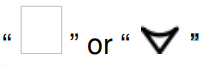 shortly to change setting temperature by 0.5°C.
 - Child-lock: Press for 3 seconds to activate child-lock.
- System mode: Press “ M ” shortly to switch cooling/heating/ventilation. (Fan Coil)
- Press “ M ” shortly to switch cooling/heating/ventilation/floor heating/floor heating + heating. (Integrated)
- Temp control mode: Press “ ” shortly to switch manual/auto mode. (Floor heating)
- Press “ ” shortly to switch manual/auto mode. (Integrated, floor heating)
- Fan speed setting: Press “ ” shortly to adjust fan speed.(Fan Cail/Integrated)
- ECO mode: Press“ ”shortly to set to ECO mode 18°C(64°F). (Floor heating)
Advanced Setting (Usually for Professional Technicians)
- Under power-off, press “ M ” for 3 seconds to enter advanced setting mode, then re-press “ M ” to switch to next mode. Press “ ” to save and exit advanced setting mode.
| Code | Meaning | |
Default Value | Integra ted | Fan Coil | Floor Heating | |
| AC2- 485 AC4 | AC2 | ||||||
| 00 | Postal address | Adjustment range 0x00~0xFA | 00 | √ | √ | × | √ |
| 01 | Temp.calibration | -9.9~9.9℃(-9~9℉) | -3℃ | √ | √ | √ | √ |
| 02 | Dead zone | 0.5~10℃(1~10℉) | ±1℃ | √ | √ | √ | √ |
| 03 | Temp. upper limit | 5~95℃(41~99℉) | 50℃ | √ | √ | √ | √ |
| 04 | Temp. lower limit | 5~47℃(41~99℉) | 5℃ | √ | √ | √ | √ |
| 05 | Frost protection | ON: frost protection on OFF: frost protection off | OFF | √ | √ | √ | √ |
| 06 | Temperature unit | ℃/℉ | ℃ | √ | √ | √ | √ |
| 07 | Sensor selection | IN: Controlled by built-in sensor OUT: Limited by floor sensor
ALL: Controlled by built-in sensor an d limited by floor sensor |
IN | √ | × | × | √ |
| 8 | Floor limited temp. | 20~90℃(68~99℉) | 35℃ | √ | × | × | √ |
| 09 | Weekly program ming setting | 12345: 5/2 week mode 123456: 6/1 week mode 1234567: 7/0 week mode | 12345 | √ | × | × | √ |
| 10 | Status of potential-free and main power outputs | 00: both outputs are normally open 0 1: main power output is normally closed; potential-free output is norma lly open 02: both outputs are normally closed 03: both outputs are normally closed; under power-off, frost protection is off either |
00 | √ | × | × | √ |
| 11 | Delay time of out puts | 0~5min | 0 | √ | × | × | √ |
| 12 | Child-lock | 00: Child-lock inactivate when screen off; lock all when child-lock activate 01: Child-lock activate when screen o ff; lock all when child-lock activate 02: Child-lock activate when screen o ff; lock all except Fan Speed, Up and Down when child-lock activate
03: Child-lock activate when screen o ff; lock all except Power on/off when child-lock activate |
00 | √ | √ | √ | √ |
| 13 | Power-on-reset | 00: stay power-off after Power-on-res et 01: stay power-on after Power-on- reset
02: recovery after Power-on-reset |
02 | √ | √ | √ | √ |
| 14 | door card status | 00: turn off door card function 01: set to ECO temp. after pulling door card out
02: stay power-off after pulling door c ard out |
00 | √ | √ | × | × |
| 15 | Door card heating ECO temp. | 10~21℃(50-69℉) | 18℃ | √ | √ | × | × |
| 16 | Door card cooling ECO temp. | 22~32℃(72-89℉) | 26℃ | √ | √ | × | × |
| 17 | Fan coil mode setting | 00: Cooling and heating 01: Cooling only | 00 | √ | √ | √ | × |
| 18 | weekly programming for Integrated | 00: turn on
01: turn off |
01 | √ | × | × | × |
| 19 | Reset | Press for 3 seconds to reset | / | √ | √ | √ | √ |
Timer Task Setting (Fan Coil / Integrated )
Press “ ” for 3 seconds to enter timer task setting; press “ M ” to change settings;
press “ ” to adjust parameters; press “ ” to save and exit.
Dimensions (Unit: mm)
Floor Heating / Fan Coil
#EP
#WP

Mounting Steps
The thermostat adopt pre-guide and limited snap-fit design. It is easy to mount.
- Release front cover by inserting a head screw-driver into bottom crack.
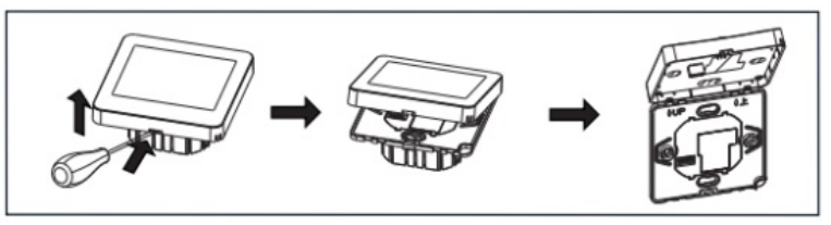
- Insert the wires and then fix these wires with screws. Suggested wire-stripping length is 7-9mm.
- Mount backing plate into wall-cassette, put screws and then fix thermostat. Make sure that the thermostat is fixed without deformation. Suggested torque is 0.2~0.4N.m (2.0~4. 1kgf.cm).
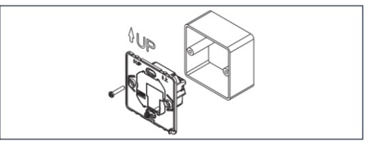
- Re-mount the front cover via snap-fit connection.

Sensor failure
Please select work mode of sensors correctly. When it shows EO/E1 error, thermostat will stay power-off till the error is eliminated. EO: built-in sensor is short-circuited or disconnected.
E1: floor sensor is short-circuited or disconnected.
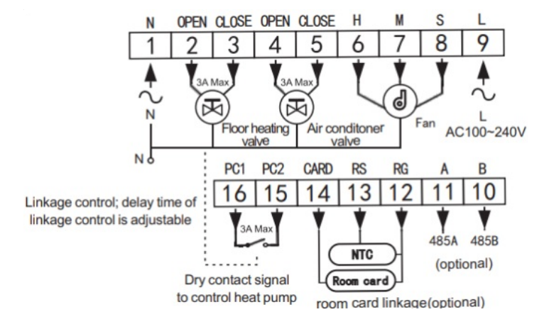
Connecting Diagram
The thermostat operates in full capacity in areas with the altitude of less than 2500 above sea level. Power rating of external load should be less than or equal to 80% rated power of the thermostat in areas with altitude of 2500m to 4200m.
Floor Heating
- #TR9B WIF EP
- # TR9B EP
- #TR9B-WIFI-WP
- # TR9B-WP
- #TR9B-WIFI-WPB
- # TR9B-WPB
 Fan Coil
- #TR9B-WIFI-AC2
- # TR9B-AC2
- #TR9B-WIFI-AC2-485
- # TR9B-AC2-485

Integrated
- #TR9B-WIFI-AWY
- # TR9B-AWY

REFERENCE
Download Manual
BEOK TR9B-WiFi LCD Smart Thermostat Instruction Manual
