
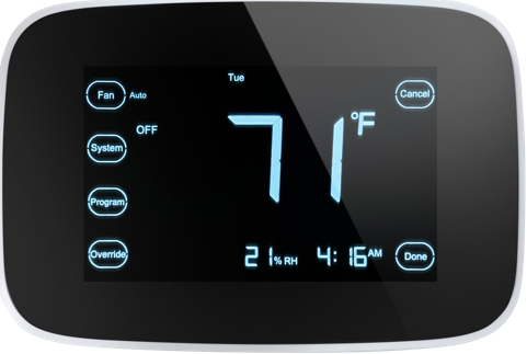
Autani 1000172-01 Wireless Thermostat
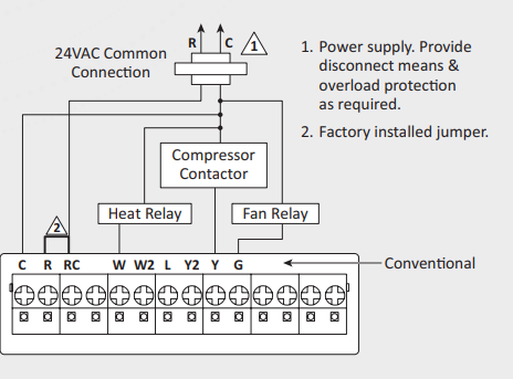
Installation
- On the provided list of thermostat serial numbers, document the location for each thermostat.
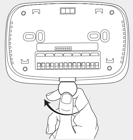
- Insert a small coin (dime) in the release slot on the bottom of the thermostat and gently twist the coin to release the thermostat from the wall plate.
Selecting Location for Mounting
Install the thermostat about 5 feet (1.5m) above the floor in an area with good air circulation at an average temperature.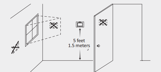
Do not install the thermostat where it can be affected by:
- Drafts or dead spots behind doors & in corners.
- Hot or cold air from ducts.
- Radiant heat from sun or appliances
- Concealed pipes and chimneys.
- Unheated or uncooled areas such as an outside wall behind the thermostat.
Installing Wall Plate
Electrical hazards can cause electrical shock or equipment damage. Disconnect power before wiring.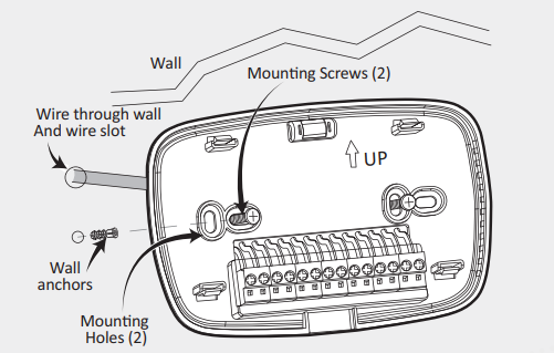
The thermostat can be mounted horizontally on the wall.
- Position and level the wall plate.
- Use a pencil to mark the mounting holes.
- Remove the wall plate from the wall and drill two holes in the wall as marked. If necessary, use the provided anchors by gently tapping them into the drilled holes until flush with the wall.
- Position the wall plate over the holes, pulling wires through the wiring opening.
- Insert the mounting screws into the holes and tighten
Wiring
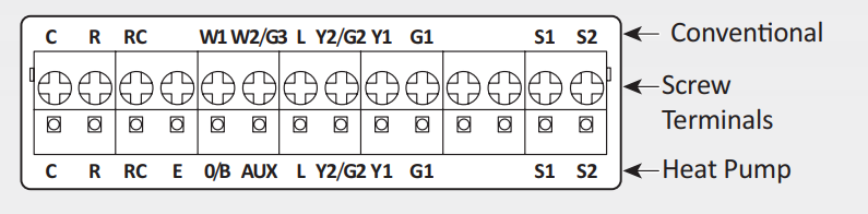
- See Table in back page for terminal designation descriptions.
- Insert wires in the terminal block under the loosened screw.
- Securely tighten each screw.
- Push excess wire back into the hole.
- Plug the hole with nonflammable insulation to prevent drafts from affecting the thermostat. Inserting wires in terminal block
Important: Use 18-gauge thermostat wire.
Notes
- If used in the single-transformer system, leave metal jumper wire in place between RC and R. In two transformer systems, remove metal jumper wire between RC and R.
- In a two-transformer system, connect the common from the secondary side of the heating system transformer.
- If the thermostat is configured for a heat pump system, configure a changeover valve for cooling or heat.
- L terminal is an input port as a system monitor.
Wiring 24VAC Common
Single-Transformer System
Connect the common side of the transformer to the C screw terminal of the thermostat wall plate. Leave the metal jumper wire in place between RC & R.
Two-Transformer System
Connect the common side of the heating transformer to the C screw terminal of the thermostat wall plate. Remove the metal jumper wire between RC and R.
Mount Thermostat to Wall Plate
Align the terminal screw blocks with the pins on the back of the thermostat. Push the thermostat straight onto the wall plate until it snaps into place.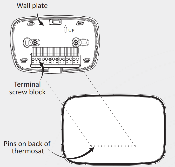
Factory Reset Instruction
- Access advanced installers menu via pressing “system” once, and then holding once the equipment type begins to flash.
- Navigate to advanced installer setting 0680 and change setting to different numbers between 1 and 10.
- Press Done until Menu has been exited.
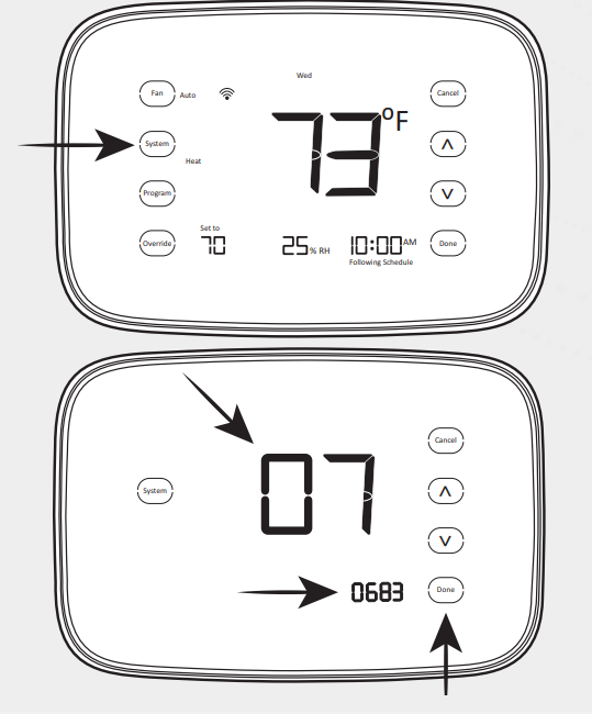
Once the Factory Reset is performed successfully, the device will search for a network and can be added through EnergyCenter®.
| Terminal | Designation |
| RC
(see note 1) |
Power for cooling – connect to secondary side of cooling system transformer |
| R
(see note 1) |
Power for heating – connect to secondary side of heating system transformer |
| C
(see note 2) |
Common wire from secondary side of heating system transformer |
| Y1 | Compressor contactor |
| G1 | Fan relay or low fan speed |
| Y2/G2 | Second-stage cooling or medium fan speed |
| O/B/W1 (see note 3) | Changeover valve for heat pump systems or heat relay |
| W2/AUX/
G3 |
Auxiliary heat relay for heat pump systems, 2nd stage heat relay, high fan speed |
| E | Emergency heat relay for heat pump systems |
| L
(see note 4) |
Equipment monitor for heat pump systems |
| S1, S2 | External temperature sensor |
Typical hookup of conventional single-stage Heat and Cool system with single transformer (1H/1C conventional)
 Typical hookup of conventional single-stage heat and cool system with two transformers (1H/1C conventional)
 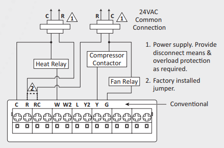 Typical hookup of heat only system with fan (1H conventional)
 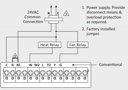 Typical hookup of cool only system (1C conventional)
 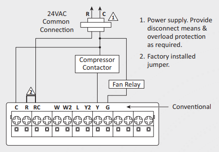 Typical hookup of conventional multistage two-stage heating & two-stage cooling in a single-transformer system (2H/2C, 2H/1C or 1H/2C conventional)
 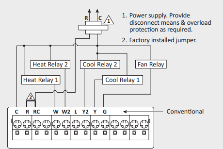 Typical hookup of conventional multistage two-stage heating and two-stage cooling in a two-transformer system (2H/2C, 2H/1C or 1H/2C conventional)
 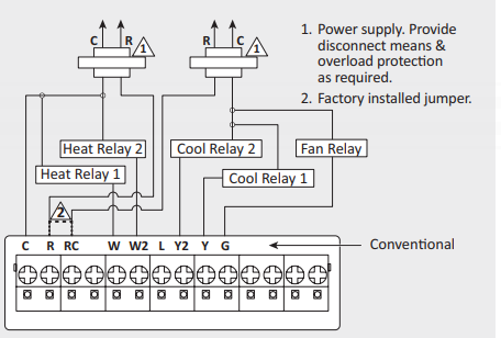 Typical hookup of single-stage heat pump with no auxiliary/backup heat (1H/1C heat pump)
 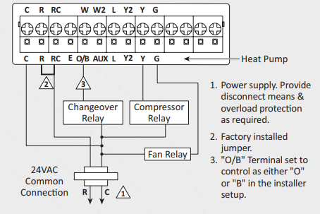 Typical hookup of single-stage heat pump with auxiliary/backup heat (2H/1C heat pump)
 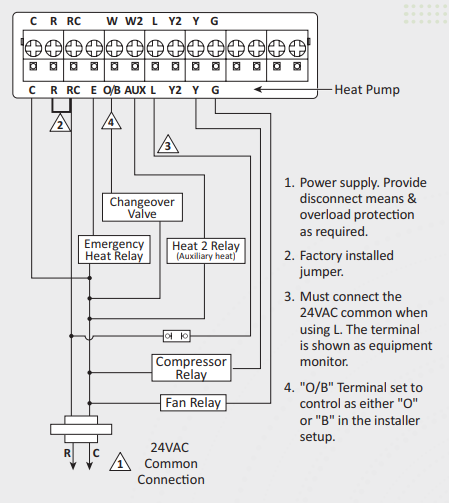 Typical hookup of multistage heat pump with auxiliary/backup heat (3H/2C heat pump)
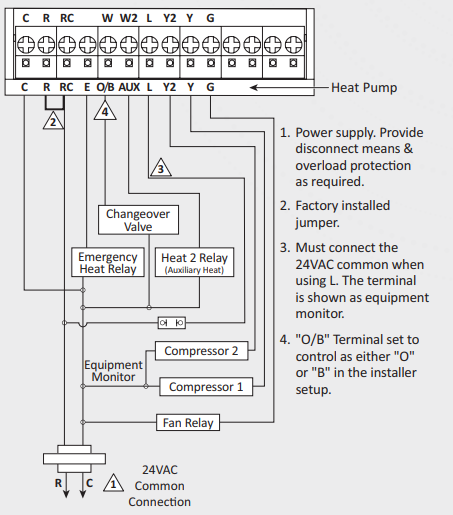
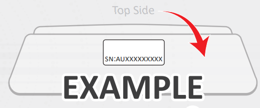
Serial Number Information and Tracking
The serial number or ID of a device is used to track device installation locations and details for the commissioning process. The identification information for each device should be tracked in a meaningful way, many devices include duplicate ‘stickers’ with this information. Autani provides an iOS app to assist with the process.
For help getting started with the iOS Commissioning App please see Autani’s User Guide for the iOS Commissioning App.
Once commissioning details are collected, either through the iOS Commissioning App or by tracking identifiers on drawings/spreadsheets.
Please provide this information to support@ autani.com to begin the commissioning process.
Reference:
Download manuals:
Autani 1000172-01 Wireless Thermostat Quick Installation Sheet
Other Manuals:
Autani 1000172-01 Wireless Thermostat Product Specification GUIDE
Autani 1000172-01 Touchscreen Programmable Thermostat Installation Guide

Autani 1000172-01 Wireless Thermostat Quick Installation Sheet
Leave a Reply