Aprilaire S86WMUPR Wi-Fi Programmable Thermostat

INSTALLATION
INSTALLATION LOCATION RECOMMENDATIONS
The thermostat should be mounted:
- On an interior wall, in a frequently occupied space.
- Approximately 5 feet above the floor.
- At least 18” from the outside wall.
- The thermostat can be mounted to a vertical junction box.
Do not mount the thermostat:
- Behind doors, in corners or other dead air spaces.
- In direct sunlight, near lighting fixtures, or other appliances that give off heat.
- On an outside or unconditioned area wall.
- In the flow of a supply register, in stairwells, or near outside doors.
- On a wall with concealed pipes or ductwork
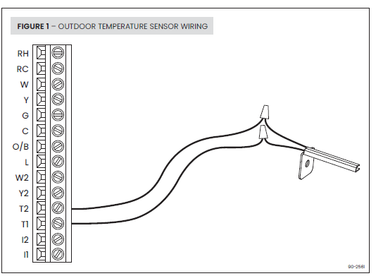
OUTDOOR TEMPERATURE SENSOR (INCLUDED)
Outdoor temperature can be measured by attaching the included 8052 sensor to the T1 and T2 terminals. The outdoor sensor must be enabled in the installer setup menu.
Heat pump models can use the outdoor temperature to effectively utilize the heat pump:
- When the outdoor temperature is lower than the Low Balance Point, the heat pump will be locked out and only auxiliary heating will be used to provide heating.
- When the outdoor temperature is higher than the High Balance Point, the auxiliary heating will be locked out and only the heat pump will be used to provide heating.
Indoor Air Quality functions can use the outdoor temperature sensor to:
- Control humidification set point based on outdoor temperature to prevent condensation.
- Lock out ventilation based on high and/or low outdoor temperatures.
- Display outdoor temperature on thermostat.
Outdoor temperature sensor should be mounted:
- On side of building out of direct sunlight (north side recommended).
- Above snow line.
- At least 3 feet away from exhaust vents and condensing lines.
- Using less than 300 feet of wire.
- Do not route wires along 120 VAC lines.
REMOTE TEMPERATURE SENSOR (OPTIONAL)
A remote temperature sensor can be used for control if the thermostat is to be mounted in a concealed location or a remote sensor can be averaged with the thermostat sensor to control a large space. An 8051 flush mount or 8053 surface mount remote temperature sensor can be attached to the T1 and T2 terminals and mounted in a recommended area. The remote sensor must be enabled in the installer set-up menu, and once enabled will override or be averaged with the thermostat’s internal temperature sensor, based on the setting.
Remote temperature sensor should be mounted:
- On an interior wall, in a frequently occupied space.
- Approximately 5 feet above floor.
- At least 18” from outside wall.
- Using less than 300 feet of wire.
Do not mount remote sensor:
- Behind doors, in corners or other dead air spaces.
- In direct sunlight, near lighting fixtures, or other appliances that give off heat.
- On an outside or unconditioned area wall.
- In the flow of a supply register, in stairwells, or near outside doors.
- On a wall with concealed pipes or ductwork.
- Near 120 VAC lines.

WIRELESS SENSORS
This thermostat is compatible with the following AprilAire wireless sensors:
- Model Z10IDT Indoor Temperature and Humidity Sensor Up to eight of these sensors can be connected to the thermostat. Connected sensors will automatically be averaged, or individual sensors can be selected for scheduled events.
- Model Z10ODT Outdoor Temperature and Humidity Sensor One sensor can be connected to the thermostat.
The wireless sensor settings can be found under the thermostats’ installer settings. See the sensors instruction manual for mounting and connecting details.
THERMOSTAT MOUNTING
- Remove the rear mounting plate from the thermostat.
- Pull wires through the opening on the back of the rear mounting plate.
- Position and level the mounting plate of the thermostat on wall and mark the hole locations with a pencil.
- Insert and tighten supplied selfdrilling anchors (drywall only).
- Place mounting plate over anchors, insert and tighten screws.
- Seal wire entry holes to prevent drafts affecting temperature readings.
POWER AND RESET OPTIONS
- The thermostat is powered by 24VAC. In the case of power loss, the thermostat will maintain the clock for 2 hours. The thermostat has a memory backup that saves the thermostat settings in case of power interruption. The thermostat can be set back to factory defaults from the installer settings menu. See Installer System Settings section for details.
- The factory reset does not clear thermostat account information from the AprilAire Wi-Fi
- Thermostat App. To clear this information, remove the thermostat from the app or use the unregister option from the thermostat’s Wi-Fi settings.
WIRING TERMINAL
WIRE SPECIFICATIONS:
- 18-24 gauge thermostat wire
INSTALLATION NOTES:
- Ensure power at the HVAC equipment is off.
- Loosen screw terminals, insert stripped wire and re-tighten.
- Push the excess wire back into the opening and plug the wall opening to prevent drafts.
| RH | 24VAC supply heating* |
| RC | 24VAC supply cooling* |
|
W |
First stage heat (conventional) / First stage auxiliary (heat pump) |
|
Y |
First stage cooling (conventional) / First stage compressor (heat pump) |
| G | Fan |
| C | Common |
| O/B | Reversing valve |
|
L |
System fault indicator (optional) (heat pump only) |
|
W2 |
Second stage heat (conventional) / Second stage auxiliary (heat pump) |
|
Y2 |
Second stage cooling (conventional) / Second stage compressor
(heat pump) |
| T1 & T2 | Outdoor/remote temperature sensor |
| I1 & I2 | Indoor Air Quality control output |
Jumper between RC & RH is used in single transformer systems (see wiring diagrams).
WIRING DIAGRAMS
FIGURE 5 – SINGLE & MULTI STAGE HEAT/COOL, ONE TRANSFORMER
NOTE: Dashed lines represent wiring for multi stage systems only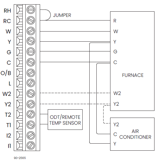
FIGURE 6 – SINGLE & MULTI STAGE HEAT/COOL, (EX: BOILER) TWO TRANSFORMER
NOTE: Dashed lines represent wiring for multi-stage systems only.
FIGURE 7 – SINGLE & MULTI STAGE HEAT PUMP, ONE TRANSFORMER
NOTE: Dashed lines represent wiring for multi-stage systems only.
FIGURE 8 – RADIANT & HEAT/COOL, ONE TRANSFORMER
FIGURE 9 – RADIANT & HEAT PUMP, ONE TRANSFORMER
FIGURE 10 – INDOOR AIR QUALITY EQUIPMENT WIRING DIAGRAMS
- DUCT-MOUNTED EVAPORATIVE HUMIDIFIERS
(APRILAIRE SERIES 400, 500, 600, 700)
- STANDALONE OR RESIDENTIAL STEAM HUMIDIFIER
(APRILAIRE SERIES 300, 800)
- DEHUMIDIFIER
(APRILAIRE SERIES 1800, e-SERIES)
- VENTILATION
(APRILAIRE SERIES 8100)
NOTE: The I1/I2 output is a dry contact closure. The HUMIDIFIER wiring diagram assumes the control is powering a solenoid valve. The DEHUMIDIFIER wiring diagram is for a normally open dry contact input. The VENTILATION wiring diagram assumes the control is for a normally closed damper. Refer to the individual humidifier, dehumidifier or ventilation installation instructions for product-specific wiring details
SETUP AND TESTING
INSTALLER SETUP WIZARD AND INSTALLER SETTING
- The first time the thermostat is powered up (or after a factory reset) it will enter the
- Installer Setup Wizard. All Installer Settings can be set through this process. The
- Installer Settings are also accessible in the Installer Menu.
HOW TO ENTER THE INSTALLER MENU:
- Press Select to enter the Main Menu.
- Use
 or
or  to navigate to Settings, press SELECT.
 - Press and hold and for 3 seconds to unlock the Installer option.
- Use or to navigate to Installer, press SELECT. Refer to the chart at right for options.
| INSTALLER MENU OPTIONS |
DESCRIPTION |
|
HVAC Settings |
Essential HVAC equipment (equipment type, stages, etc.) |
|
HVAC Advanced |
Advanced HVAC control (effsets, headbands, staging, protection, etc.) |
|
IAQ Settings |
Humidifier, Dehumidifier, Air Cleaner, and Ventilation configuration |
|
Wireless Sensor |
Connect/disconnect wireless indoor and outdoor sensors |
|
Test |
Installer test for configured equipment relay outputs |
| Reset | Reset all settings to factory default |
HVAC INSTALLER SYSTEM SETTINGS TABLE
The following table contains the system settings and their details. Default settings are shown in bold. The availability of some settings is dependent upon the value of other settings.
| TABLE 1 – HVAC INSTALLER SYSTEM SETTINGS | ||
|
System setting |
Description |
Factory default setting (bold) and setting range |
|
Equipment Type |
NOTE: Equipment Type related settings will return to defaults if this is changed. | Heat/Cool
Heat Pump |
| O/B Energized For? | Selects O or B reversing valve operation. (Heat Pump mode only.) | Cooling
Heating |
|
Control Setup |
Used to lockout heating or cooling outputs. (Heat/Cool mode only). | Heat & Cool Heat Only Cool Only |
| Heat Pump Auxiliary Type | Selects auxiliary type. (Heat Pump mode only.) | Gas/Oil Heat
Electric Heat |
| Fan Control in Heating | Selects thermostat or equipment to control the fan in heating. (Heat/Cool mode only.) | Gas/Oil Heat
Electric Heat |
| TABLE 1 – HVAC INSTALLER SYSTEM SETTINGS | ||
|
System setting |
Description |
Factory default setting (bold) and setting range |
| Number of Compressor Stages | Select number of compressor stages. (Heat Pump mode only.) | One
Two |
| Number of Auxiliary Heat Stages | Select number of auxiliary heat stages. (Heat Pump mode only.) | One
Two |
| Number of Stages of Heat | Select number of heat stages. (Heat/ Cool mode only.) | One
Two |
| Number of Stages of Cool | Select number of cool stages. (Heat/ Cool mode only.) | One
Two |
| Programmable | Non Programmable hides all scheduling features. | Programmable
Non Programmable |
|
Wired Temperature Sensor Installed? |
Selects how the external temperature sensor terminals (T1 & T2) are being used. Choose Outdoor for a wired outdoor sensor or Remote/Remote Average for a wired indoor sensor. |
Outdoor Remote
(Onboard sensor disabled) Remote Average (Average with onboard sensor) No (No external sensor connected) |
| TABLE 1 – HVAC INSTALLER SYSTEM SETTINGS | ||
|
System setting |
Description |
Factory default setting (bold) and setting range |
|
Outdoor Temperature Data Provided From? |
Select where the outdoor temperature data comes from. (This option is not available if you are using the wired outdoor temperature sensor.) |
Web
Automation (for home automation config only) None Wireless (Wireless outdoor sensor) |
| Advanced HVAC Settings? | Select No to skip the rest of the thermostat settings. | No
Yes |
|
Connection Type |
Selects if the thermostat connects with an automation system or an AprilAire account. | AprilAire Cloud
Automation System |
| Progressive Recovery | Enables or disables progressive recovery. | Disabled
Enabled |
| Display Heat Blast? | Select if the Heat Blast option is displayed. | No
Yes |
|
Heat Blast Offset |
Amount of heating when Heat Blast is initiated. | 3°F (1.5°C)
4°F (2°C) 5°F (2.5°C) |
| TABLE 1 – HVAC INSTALLER SYSTEM SETTINGS | ||
|
System setting |
Description |
Factory default setting (bold) and setting range |
| Extended Fan – Heat | Extends fan operation 90 seconds after heat call ends. NOTE: Only available with electric heat. | Disabled
Enabled |
| Extended Fan – Cool | Extends fan operation 90 seconds after cool call ends. | Disabled
Enabled |
| Auto Changeover | Enable or disable Auto Changeover mode. | Disabled
Enabled |
| DeadBand | Auto Changeover mode deadband. | 3°F (1.5°C)
2 to 9°F (1 to 4.5°C) |
| Auto Changeover Time | Minimum time between heating and cooling calls. | 4 Minutes
1 to 5 Minutes |
| Temp Sensor Offset | Field adjustment of controlling temperature sensors. | 0°F (0°C)
-4 to 4°F (-2 to +2°C) |
| RH Sensor Offset | Internal RH sensor. Increases or decreases displayed RH%. | 0
-5 to 5 |
| Equipment Minimum On Time | Minimum on time for heating and cooling. | 2 Minutes
1 to 5 Minutes |
| TABLE 1 – HVAC INSTALLER SYSTEM SETTINGS | ||
|
System setting |
Description |
Factory default setting (bold) and setting range |
| Heating Minimum Off Time | Minimum off time for heating. | 2 Minutes
1 to 5 Minutes |
| Compressor Minimum Off Time | Minimum off time for compressor protection. | 5 Minutes
1 to 5 Minutes |
| Outdoor Temperature High Balance Point | Enable or disable high balance point. (Available if an ODT is installed.) | Enabled
Disabled |
|
High Balance Point Temperature |
If outside temperature is above the high balance point the aux heat operation is not allowed. (Available if high balance point is enabled.) |
65°F (14.5°C) 0 to 80°F (-18 to 22°C) |
| Outdoor Temperature Low Balance Point | Enable or disable low balance point. (Available if an ODT is installed.) | Enabled
Disabled |
|
Low Balance Point Temperature |
If outside temperature is below the low balance point the compressor operation is not allowed. (Available if low balance point is enabled.) |
20°F (-8°C) 0 to 60°F (-18 to 12°C) |
| TABLE 1 – HVAC INSTALLER SYSTEM SETTINGS | ||
|
System setting |
Description |
Factory default setting (bold) and setting range |
|
Stage Rate |
Accumulation of difference from setpoint over time in staging determination. | Enabled
Disabled |
|
Stage Rate Factor |
1 = more rapid staging of equipment (comfort),
5 = slower staging of equipment (economy). |
2 1 to 5 |
| First Stage Differential | First stage differential. | 1°F (0.5°C)
1 to 9°F (0.5 to 4.5°C) |
| Second Stage Differential | Second stage differential. | 1°F (0.5°C)
1 to 9°F (0.5 to 4.5°C) |
| Third Stage Differential | Third stage differential. | 1°F (0.5°C)
1 to 9°F (0.5 to 4.5°C) |
| Fourth Stage Differential | Fourth stage differential. | 1°F (0.5°C)
1 to 9°F (0.5 to 4.5°C) |
| Service HVAC Reminder | Enable or disable the HVAC Service reminder message. | Disabled
Enabled |
| TABLE 1 – HVAC INSTALLER SYSTEM SETTINGS | ||
|
System setting |
Description |
Factory default setting (bold) and setting range |
| Recurrence | Select number of months between HVAC Service reminder messages. | 12 Months
1 to 12 Months |
| Max Heat Setting | Select the maximum heating set point temperature allowed. | 90°F (32°C)
40 to 90°F (4.5 to 32°C) |
| Min Heat Setting | Select the minimum heating set point temperature allowed. | 40°F (4.5°C)
40* to 90°F (4.5 to 32°C) |
| Max Cool Setting | Select the maximum cooling set point temperature allowed. | 99°F (37°C)
50 to 99°F (10 to 37°C) |
| Min Cool Setting | Select the minimum cooling set point temperature allowed. | 50° (10°C)
50 to 99°F (10 to 37°C) |
INDOOR AIR QUALITY SYSTEM SETTINGS TABLES
The following tables contain the Indoor Air Quality system settings and their details. Default settings are shown in bold. The availability of some settings is dependent upon the value of other settings. The use of outdoor temperature data enables additional Indoor Air quality functionality. While the outdoor temperature sensor option was presented in the HVAC installer settings, it is also available in the Indoor Air Quality settings. Please refer to the Owner’s Manual for further information about thermostat features
| TABLE 2 – HUMIDIFIER SYSTEM SETTINGS | ||
|
System setting |
Description |
Factory default setting (bold) and setting range |
| NOTE: A humidifier can only be installed if ventilation is not installed and dehumidifier control is not set to Whole Home. | ||
|
Humidifier Installed? |
Selects whether a humidifier is installed. Yes/On HVAC is used for applications where the humidifier is installed on the HVAC duct. Yes/Standalone is used for applications where the humidifier is independent from the HVAC system. (If set to No, no other humidifier settings will be available.) |
No Yes/On HVAC Yes/Standalone |
| TABLE 2 – HUMIDIFIER SYSTEM SETTINGS | ||
|
System setting |
Description |
Factory default setting (bold) and setting range |
| Outdoor | ||
| Wired Temperature Sensor Installed? | Selects how the external temperature sensor terminals (T1 & T2) are being used. Choose Outdoor for a wired outdoor sensor or Remote/Remote Average for a wired indoor sensor. | Remote
(Onboard sensor disabled) Remote Average (Average with onboard sensor) No (No external sensor connected) |
| Web | ||
| Outdoor Temperature Data Provided From? | Select where the outdoor temperature data comes from. (This option is not available it you are using the wired outdoor temperature sensor) | Automation
(for home automation config only) None Wireless (Wireless outdoor sensor) |
|
Humidifier Mode |
Selects auto or manual mode. Auto mode controls humidity based on the humidity setting and outdoor temperature. Manual mode controls humidity based on the
%RH setpoint. (Auto mode is only available if an outdoor sensor option is enabled.) |
Auto Manual |

| TABLE 2 – HUMIDIFIER SYSTEM SETTINGS | ||
|
System setting |
Description |
Factory default setting (bold) and setting range |
|
Humidifier Reminder |
Selects when the “Change Water Panel” message is displayed. |
Off
150h Valve 300h Valve 600h Valve 1 per season 2 per season |
|
Single or First Reminder Appears |
Determines the month the first (or only) “Change Water Panel” message is displayed. |
October April
November May December June January July February August March September |
|
Second Reminder Appears |
Determines the month the second “Change Water
Panel” message is displayed. (Only available when 2 reminders per season is selected.) |
October April
November May December June January July February August March September |
| TABLE 3 – DEHUMIDIFIER SYSTEM SETTINGS | ||
|
System setting |
Description |
Factory default setting (bold) and setting range |
| NOTE: Dehumidifier control can only be set to Whole Home if ventilation and humidification are not enabled. | ||
|
Dehumidifier Type Installed? |
Selects if a dehumidifier is installed. (If set to None, no other dehumidifier settings will be available.) AC w/ IAQ selects overcooling,
I1 and I2 terminals energize during overcooling. AC w/o IAQ selects overcooling, I1 and I2 terminals are not used. |
None Whole Home AC w/ IAQ AC w/o IAQ |
| Disable Dehumidification During Cooling? | Selects if dehumidification is disabled during a cooling call. | Yes
No |
| Dehumidifier Forces Fan? | Selects if dehumidification can turn on the HVAC system fan. | Yes
No |
| Dehumidifier Overcool Limit | Selects the amount of overcooling that can occur for dehumidification. (Only available if dehumidifier type is set to Overcool.) | 1°F (0.5°C)
2°F (1°C) 3°F (1.5°C) |
| TABLE 3 – DEHUMIDIFIER SYSTEM SETTINGS | ||
|
System setting |
Description |
Factory default setting (bold) and setting range |
| Dehumidifier Reminder | Enable or disable the Dehumidifier Service reminder message. | Disabled
Enabled |
| Recurrence | Select number of months between Dehumidifier Service reminder messages. | 12 Months
1 to 12 Months |
| Dehumidify in Vacation Hold? | Selects if dehumidification with the air conditioner is done in vacation mode. | No
Yes |
|
Vacation Hold Low Temperature Limit |
Sets the lowest temperature the air conditioner will cool to, to meet RH setpoint in Vacation Mode. (Only available if dehumidifier type is set to Overcool.) |
75°F (24°C) 70 to 85°F (21 to 29.5°C) |
|
Humidity Deadband |
Select the minimum difference between the humidifier and dehumidifier setpoints. (Only available if both Humidifier and Dehumidifier are enabled.) |
10% 10 to 20% |
| TABLE 4 – AIR CLEANING SYSTEM SETTINGS | ||
|
System setting |
Description |
Factory default setting (bold) and setting range |
|
Air Cleaner Installed? |
Selects if an air cleaner is installed.
(If set to No, no other air cleaner settings will be available.) |
No
Yes |
| Air Cleaner Reminder | Enable or disable the Change Air Filter message. | Disabled
Enabled |
| Recurrence | Select number of months between Change Air Filter messages. | 12 Months
1 to 12 Months |
| TABLE 5 – FRESH AIR VENTILATION SYSTEM SETTINGS | ||
|
System setting |
Description |
Factory default setting (bold) and setting range |
| NOTE: Ventilation can only be installed if humidification is not enabled and dehumidifier control is not set to Whole Home. | ||
| Fresh Air Vent Installed? | Selects if ventilation is installed. (If set to No, no other ventilation settings will be available.) | No
Yes |
|
Fresh Air Setup Type |
Selects if ventilation is configured through the Code setup or Comfort. Comfort setup has more lockout options. Code setting ensures time missed due to lockouts is made up. |
Comfort Code |
| Number of Bedrooms | Selects the number of bedrooms to be used for the Calculated Minutes per Hour. | 3 Bedrooms
1 to 10 Bedrooms |
| Square Footage | Selects the size of the home to be used for the Calculated Minutes per Hour. | 2500 SQ FT
500 to 7500 SQ FT |
| Measured CFM | Selects the ventilation CFM to be used for the Calculated Minutes per Hour. | 110 CFM
30 to 250 CFM |
| TABLE 5 – FRESH AIR VENTILATION SYSTEM SETTINGS | ||
|
System setting |
Description |
Factory default setting (bold) and setting range |
| Calculated Minutes Per Hour |
Displays the Fresh Air Time calculated. |
None
Range 6 to 60 Minutes |
| Override | Manual adjustment of Calculated Minutes per Hour. | (Calculated Minutes per Hour)
Range 6 to 60 Minutes |
|
Wired Temperature Sensor Installed? |
Selects how the external temperature sensor terminals (T1 & T2) are being used. Choose Outdoor for a wired outdoor sensor or Remote/Remote Average for a wired indoor sensor. |
Outdoor Remote
(Onboard sensor disabled) Remote Average (Average with onboard sensor) No (No external sensor connected) |
|
Outdoor Temperature Data Provided From? |
Select where the outdoor temperature data comes from. ( This option is not available it you are using the wired outdoor temperature sensor) |
Web
Automation (for home automation config only) None Wireless (Wireless outdoor sensor) |
| TABLE 5 – FRESH AIR VENTILATION SYSTEM SETTINGS | ||
|
System setting |
Description |
Factory default setting (bold) and setting range |
|
High Vent RH Limit |
Selects if ventilation is disabled when the indoor RH exceeds the indoor RH limit. (Only available if Fresh Air Setup is set to Comfort.) |
Disabled Enabled |
| High Vent RH Limit | Sets the ventilation indoor RH lockout limit. (Only available if High Vent RH Limit is set to Enabled.) | 55%
45% to 70% |
|
Low Vent RH Limit |
Selects if ventilation is disabled when the indoor RH exceeds the indoor RH limit. (Only available if Fresh Air Setup is set to Comfort.) |
Disabled Enabled |
| Low Vent RH Limit | Sets the ventilation indoor RH lockout limit. (Only available if Low Vent RH Limit is set to Enabled.) | 20%
10% to 30% |
| High Vent Temperature Limit | Enables high ventilation temperature lockout limit. (Only available if an outdoor sensor option is enabled.) | Disabled
Enabled |
| TABLE 5 – FRESH AIR VENTILATION SYSTEM SETTINGS | ||
|
System setting |
Description |
Factory default setting (bold) and setting range |
| High Vent Temperature Limit | Sets high ventilation temperature lockout limit. (Only available if High Vent Temperature Limit is set to Enabled.) | 100°F (38°C)
85°F to 105°F (29°C to 41°C) |
| Low Vent Temperature Limit | Enables low ventilation temperature lockout limit. (Only available if an outdoor sensor option is enabled.) | Disabled
Enabled |
| Low Vent Temperature Limit | Sets low ventilation temperature lockout limit. (Only available if Low Vent Temperature Limit is set to Enabled.) | 10°F (-12°C)
-10°F to 40°F (-24°C to 6°C) |
|
HVAC Fan with Vent? |
Selects if ventilation forces the fan on. (Yes with high and low limits is only available if an outdoor sensor option is enabled.) | Yes
Yes with high and low limits No |
| High Mixing Temperature | Enables high mixing temperature. (Only available is HVAC Fan with Vent is set to Yes with high and low limits.) | Disabled
Enabled |
| High Mixing Temperature | Sets the high mixing temperature. (Only available if High Mixing Temperature is set to Enabled.) | 80°F or (26°C)
60°F to 105°F (14°C to 41°C) |
| TABLE 5 – FRESH AIR VENTILATION SYSTEM SETTINGS | ||
|
System setting |
Description |
Factory default setting (bold) and setting range |
| Low Mixing Temperature | Enables low mixing temperature. (Only available is HVAC Fan with Vent is set to Yes with high and low limits.) | Disabled
Enabled |
| Low Mixing Temperature | Sets the Low mixing temperature. (Only available if Low Mixing Temperature is set to Enabled.) | 40°F (6°C)
0°F to 50°F (-18°C to 12°C) |
| Fresh Air Reminder | Enable or disable the Service Fresh Air message. | Disabled
Enabled |
| Recurrence | Select number of months between Service Fresh Air messages. | 12 Months
1 to 12 Months |
The system test menu is used to test a system after installation. The Installer Test can be accessed from the Installer Menu. All equipment outputs that are configured in the installer settings can be turned on and off for testing equipment. Minimum on and off times are not enforced while in this mode. The instructions below show how to enter the test mode and turn outputs on and off.
ENTER THE SYSTEM TEST MENU
- Press Select to enter the Main Menu.
- Use or to navigate to Settings, press Select.
- Press and hold and for 3 seconds to unlock the Installer option.
- Use or to select Installer Settings, press Select.
- Use or to select System Test, press Select.
SYSTEM TEST STEPS
- Heating equipment test.
- Cooling equipment test.
- Fan equipment test.
- Humidification equipment test.
- Dehumidification equipment test.
- Ventilation equipment test.

WI-FI SETUP
For detailed instructions for connecting the thermostat to a Wi-Fi network and registering it to an AprilAire account, refer to the Wi-Fi Quick Start Guide included in the box.
QUICK REFERENCE TO CONTROLS & DISPLAY
HOME SCREEN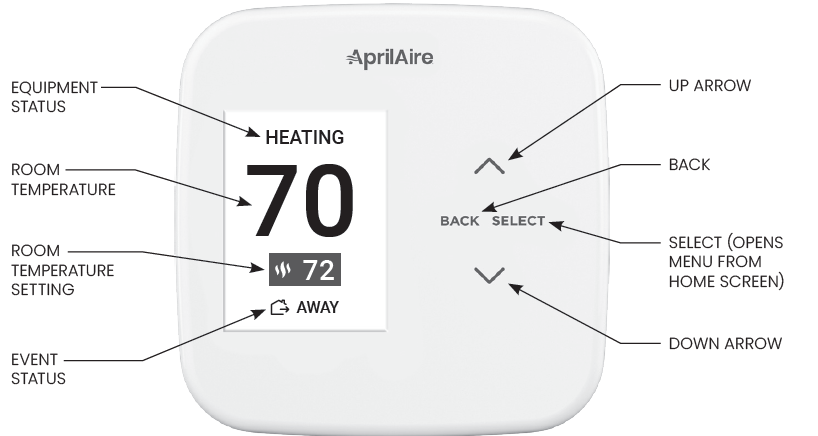
MAIN MENU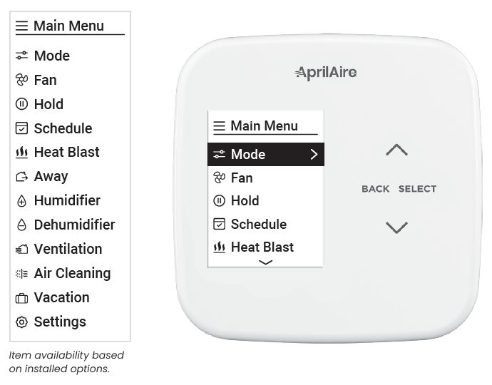
Item availability based on installed options
SCREEN SAVER
Starts 45 seconds after inactivity, press any button to wake the screen
TROUBLESHOOTING
DISPLAY IS BLANK
- Check circuit breaker and reset if necessary.
- Make sure power switch at heating & cooling system is on.
- Make sure the furnace door is closed securely.
THE HEATING SYSTEM DOES NOT RESPOND (“HEATING” APPEARS ON SCREEN)
- Check for 24VAC at the equipment on the secondary side of the transformer between power and common. If voltage is not present, check the heating equipment to find the cause of the problem.
- Check for 24VAC between the heat terminal (W) and the transformer common. If 24VAC is present, the thermostat is functional.
- Check the heating equipment to find the cause of the problem.
- Check for loose or broken wires between the thermostat and the heating equipment
TEMPERATURE SETTINGS DO NOT CHANGE
Make sure heating and cooling temperatures are set to acceptable ranges:
- Heat: 40° to 90°F (4° to 32°C).
- Cool: 50° to 99°F (10° to 37°C).
THE COOLING SYSTEM DOES NOT RESPOND (“COOLING” APPEARS ON SCREEN)
- Check for 24VAC at the equipment on the secondary side of the transformer between power and common. If voltage is not present, check the cooling equipment to find the cause of the problem
- Check for 24VAC between the cooling terminal (Y) and the transformer common. If 24VAC is present, the thermostat is functional. Check the cooling system to find the cause of the problem.
- Check for loose or broken wires between the thermostat and the cooling equipment
THE FAN DOES NOT TURN ON IN A CALL FOR HEAT
Check System Setting (Fan Control in Heating), to make sure the fan control is properly set to match the type of system (see page 19).
HEAT PUMP ISSUES COOL AIR IN HEAT MODE, OR WARM AIR IN COOL MODE
Check System Setting (O/B Operation) to make sure the reversing valve operation matches the heat pump.
HEAT/COOL BOTH ON AT SAME TIME
- Check System Setting (Equipment Type), to make sure it is set to match the installed heating/cooling equipment (see page 19).
- Check to make sure heating and cooling wires are not shorted together.
HEATING EQUIPMENT IS RUNNING IN COOL MODE
- Check System Setting (Equipment Type), to make sure it is set to match the installed heating/cooling equipment (see page 19).
“HEATING” IS NOT DISPLAYED
- Check System Setting (Control Setup) is set correctly.
- Change the System Mode to Heat, and set the temperature level above the current room temperature.
“COOLING” IS NOT DISPLAYED
- Check System Setting (Control Setup) is set correctly.
- Change the System Mode to Cool, and set the temperature level below the current room temperature.
HUMIDIFIER DOES NOT OPERATE IN AUTO MODE
- Check Installer System Setting number (Outdoor Sensor) is set to Yes.
- Verify that the outdoor sensor is functioning correctly. If the sensor is functioning correctly the outdoor temperature will display in the outdoor temperature location (see SCREEN SAVER on page 42 for the location).
ERROR CODES
If the thermostat enters an error mode, all outputs are turned off. The thermostat attempts to recover every 10 minutes
| Error Code | Message | Error Description |
| E01 | Sensor Error | Internal temperature & RH sensor failure |
| E03 | EEPROM Error | Error in permanent memory |
| E06 | Remote Sensor Error | Open remote temperature sensor circuit |
| E07 | Remote Sensor Error | Shorted remote temperature sensor circuit |
THERMOSTAT FEATURES
- Remote access and control over Wi-Fi.
- Indoor air quality control.
- Humidification automatic or manual control.
- Dehumidification.
- Event-Based™ air cleaning.
- Ventilation with temperature and humidity limits.
- Heat Blast® raises the room temperature 3°F to 5°F.
- Easy to read, color graphical display.
- Easy to use installer settings, no codes.
- 7 day programmability.
- Displays room temperature, room humidity, temperature setting, and outdoor temperature.
- Air filter, humidifier, dehumidifier, and HVAC service reminders.
- Programmable fan control with fan circulation mode.
- Easy to use temperature control can override program schedule at any time.
- Progressive recovery ensures proper room temperature at the start of a program event.
- Built in compressor protection prevents damage to your equipment.
- System test mode.
- Optional wireless indoor and outdoor sensors.
- Sensor averaging and the ability to assign a sensor to a scheduled event.
- Installer adjustable set point limits.
SPECIFICATIONS
| ENVIRONMENT | |
| Temperature | Operating: 32° to 120°F (0° to 48.9°C)
Shipping: -30° to 150°F (-34.4° to 65.5°C) |
| Relative humidity | Operating: 5% to 90% R.H. (non-condensing) |
| ELECTRICAL | |
| Operating voltage | 24VAC (18–30VAC) |
| Current | Maximum: 2.5A (total), 1.0A (single output)
Maximum surge current: 5A |
| THERMAL | |
| Outdoor & Remote temperature sensor | Maximum distance: 300 feet |
| Room temperature measurement | Display range: 32° to 99°F (0° to 40°C) |
| Outdoor temperature measurement | Display range: -40° to 130°F (-40° to 55°C) |
| Setpoint temperature range | Heat: 40° to 90°F (4° to 32°C)
Cool: 50° to 99°F (10° to 37°C) |
| Setpoint humidity range | Humidification: 10% to 50% R.H.
Dehumidification: 40% to 90% R.H. |
B2208826C
61001878
7.22
© 2022 AprilAire
aprilairepartners.com
800.334.6011 U.S. Patent Numbers 8,146,376, 8,596,078, 9,874,366 and other patents pending. Aprilia reserves the right to change specifications without notice.
REFERENCE
Download Manual:
Aprilaire S86WMUPR Wi-Fi Programmable Thermostat Installation Instruction
other manuals:
Aprilaire S86WMUPR Wi-Fi Programmable Thermostat Quick Start Guide
![]()
Aprilaire S86WMUPR Wi-Fi Programmable Thermostat Installation Instruction