Aprilaire 8840 Automation Thermostat

INSTALLATION
THERMOSTAT INSTALLATION LOCATION RECOMMENDATIONS
The thermostat should be mounted:
- On an interior wall, in a frequently occupied space.
- Approximately 5‘ above the floor.
- At least 18” from the outside wall.
- The thermostat can be mounted to a vertical junction box.
Do not mount the thermostat:
- Behind doors, in corners or other dead air spaces.
- In direct sunlight, near lighting fixtures, or other appliances that give off heat.
- On an outside or unconditioned area wall.
- In the flow of a supply register, in stairwells, or near outside doors.
- On a wall with concealed pipes or ductwork.
THERMOSTAT MOUNTING
- Remove the rear mounting plate from the thermostat.
- Pull wires through the opening on the rear mounting plate.
- Position and level the mounting plate of the thermostat on wall and mark the hole locations with a pencil.
- Drill 1/4” holes and insert supplied anchors (drywall only).
- Place mounting plate over anchors, insert and tighten screws.
- Seal wire entry holes to prevent drafts affecting temperature readings.
EQUIPMENT CONTROL MODULE INSTALLATION LOCATION RECOMMENDATIONS
Note: Installer must touch a grounded metal object before handling the equipment control module to avoid potential damage due to electrical discharge.
Equipment control module should be mounted:
- In a location where the temperature will not exceed 158°F (70°C) or drop below 32°F (0°C).
Do not mount equipment control module:
- On foundation walls or on the HVAC equipment or ductwork. These locations can cause moisture to condense on the equipment control module.
EQUIPMENT CONTROL MODULE MOUNTING
The equipment control module has the following features to simplify mounting and wiring and provide for a clean and neat installation.
- Six (6) mounting holes. One on each corner and two centered top and bottom. Any combination of these holes may be utilized. Mount the equipment control module using 2 to 4 #8 screws appropriate for the mounting surface substrate. (See Figure 2.)
- Wires can be routed through the top, bottom, sides or back.
- Nylon wire ties can be used to secure wires in 10 places.
Installation Steps
- Select mounting location.
- Pull from bottom to remove front cover. (See Figure 1.)
- Mount base using 2 to 4 #8 screws (field supplied).
THERMOSTAT WIRING

Wire specifications:
18-24 gauge thermostat wire
Installation notes:
- Ensure power at the HVAC equipment is off.
- Loosen screw terminals, insert stripped wire and re-tighten.
- Push the excess wire back into the opening and plug the wall opening to prevent drafts.
- Connection to terminal 1 at equipment control module
- Connection to terminal 2 at equipment control module
- Connection to terminal 3 at equipment control module
- A & B – Model 8081 or Model 8082 support module communication (optional)
- T1 & T2 – Remote temperature sensor (optional)
REMOTE TEMPERATURE SENSOR (OPTIONAL)
A remote temperature sensor can be used for control if the thermostat is to be mounted in a concealed location or a remote sensor can be averaged with the thermostat sensor to control a large space. An 8051 flush mount
or 8053 surface mount remote temperature sensor can be attached to the T1 and T2 terminals and mounted in a recommended area. The remote sensor must be enabled in the installer setup menu, and once enabled will override or be averaged with the thermostat’s internal temperature sensor, based on the setting.
Remote temperature sensor should be mounted:
- On an interior wall, in a frequently occupied space.
- Approximately 5‘ above floor.
- At least 18” from outside wall.
- Using less than 300’ of wire.
Do not mount remote sensor:
- Behind doors, in corners or other dead air spaces.
- In direct sunlight, near lighting fixtures, or other appliances that give off heat.
- On an outside or unconditioned area wall.
- In the flow of a supply register, in stairwells, or near outside doors.
- On a wall with concealed pipes or ductwork.
- Near 120 VAC lines.
SUPPORT MODULE WIRING (OPTIONAL)
- Up to 4 support modules can be wired for remote sensing of temperature and/or humidity. Each sensor can be configured for control or monitoring.
- Note: Support modules should be wired with CAT-5 wire. The total length of wire for all support modules should not exceed 1000 feet.
EQUIPMENT CONTROL MODULE WIRING
Wire specifications:
18-24 gauge thermostat wire
Installation notes:
- Ensure power at the HVAC equipment is off.
- Loosen screw terminals, insert stripped wire and re-tighten.
- Use zip tie to route wiring through the wiring channels.
- Connection to terminal 1 at thermostat
- Connection to terminal 2 at thermostat
- Connection to terminal 3 at thermostat
- RAT – Return air temperature sensor (optional)
- LAT – Leaving air temperature sensor (optional)
- ODT – Outdoor temperature sensor (included)
- C – 24VAC common
- R – 24VAC
- RC – 24VAC cooling
- RH – 24VAC heating
- W – First stage heat (conventional)/auxiliary (heat pump) W2 – Second stage heat (conventional)/ auxiliary (heat pump)
- W3/B – Third stage heat (conventional)/reversing valve (heat pump)
- Y – First stage cooling (conventional)/first stage compressor (heat pump)
- Y2 – Second stage cooling (conventional)/second stage compressor (heat pump).
- Y3/0 – Third stage cooling (conventional)/reversing valve (heat pump)
- G – Fan
- L – System fault indicator (heat pump only) (optional)
- CEQ – 24VAC common from heat pump for system fault indicator (optional)
- HUM – Humidifier
- DHno & DHcom – Normally open dehumidifier control DHnc & DHcom – Normally closed dehumidifier control VENT – Ventilation
- EAC – Electronic Air Cleaner
OUTDOOR TEMPERATURE SENSOR (INCLUDED)
Outdoor temperature can be measured by installing an 8052 sensor to the ODT terminals and enabling the outdoor sensor in the installer setup menu. When an outdoor sensor is installed, the features below will be enabled.
In heat pump mode the outdoor temperature sensor can be used to efficiently utilize an air source heat pump:
- When the outdoor temperature is less than the Low Balance Point, the heat pump will be locked out and only auxiliary heating will be used to provide heating.
- When the outdoor temperature is higher than the High Balance Point, the auxiliary heating will be locked out and only the heat pump will be used to provide heating.
Indoor Air Quality functions can use the outdoor temperature sensor to:
- Control humidification setpoint based on outdoor temperature to prevent condensation
- Lock out humidification for temperatures over 60°F or below -30°F.
- Lock out ventilation based on high and/or low outdoor temperatures.
- Display outdoor temperature on thermostat.
Outdoor temperature sensor should be mounted:
- On side of building out of direct sunlight (north side recommended).
- Above snow line.
- At least 3’ away from exhaust vents and condensing lines.
- Using less than 300’ of wire.
- Do not route wires along 120 VAC lines.
OPTIONAL WIRELESS OUTDOOR TEMPERATURE SENSOR
- For installations where it is difficult to wire the included 8052 outdoor temperature sensor, a Model 8056 wireless outdoor temperature module can be used. The Model 8056 module has two radio units, one that is placed on the equipment control module as shown below, and a second radio that is placed outside. See the Model 8056 Installation Instructions for detailed directions regarding installation.
RETURN AIR TEMPERATURE SENSOR (OPTIONAL)
Return air temperature can be measured by attaching an 8052 sensor to the RAT terminals. The return sensor must be enabled in the installer setup menu. The return air temperature sensor provides protection in the event that the equipment control module loses connection with the thermostat. In the event that the thermostat connection is lost, the equipment control module will use the return air temperature sensor to maintain a temperature greater than 40°F and less than 100°F.
- Locate the Aprilaire Model 8052 sensor in the return trunk.
- Mount the sensor according to the installation instructions provided with the sensor.
- Wire the sensor to the equipment control module RAT terminals.

LEAVING AIR TEMPERATURE SENSOR (OPTIONAL)
Leaving air temperature can be measured by attaching an 8052 sensor to the LAT terminals. The leaving air temperature sensor measurement is displayed during the installer test for diagnostic purposes.
IMPORTANT
Do not mount the sensor in direct line of sight of the heat exchanger, cooling coils, or UV lights as this may cause the sensor to report false temperature readings.
- Locate the Aprilaire Model 8052 sensor in the supply trunk, after the heat exchanger and cooling coils. (See shaded areas in figure below.)
- Mount the sensor according to the installation instructions provided with the sensor.
- Wire the sensor to the equipment control module LAT terminals.
HVAC WIRING DIAGRAMS
CONVENTIONAL HEAT/COOL SINGLE TRANSFORMER (USE JUMPER)
CONVENTIONAL HEAT/COOL TWO TRANSFORMERS (REMOVE JUMPER)
HEAT PUMP SINGLE TRANSFORMER (USE JUMPER WIRE)
HEAT PUMP TWO TRANSFORMER (REMOVE JUMPER WIRE)
INDOOR AIR QUALITY WIRING DIAGRAMS
INDOOR AIR QUALITY WIRING WITH SEPARATE TRANSFORMERS
Note: Outputs are 24VAC dry contact. Refer to individual product installation instructions for more details.
INDOOR AIR QUALITY WIRING WITH A SINGLE TRANSFORMER
Note: Outputs are 24VAC dry contact. Refer to individual product installation instructions for more details.
POWER & RESET OPTIONS
The equipment control module is powered from 24VAC. The thermostat is powered from the equipment control module. In the case of power loss the thermostat will maintain the clock for 24 hours. The thermostat has a memory backup that saves the thermostat settings in case of power interruption.
The factory reset is located in the Installer Tools option of the Installer Menu. See Installer System Settings section for details.
SETUP & TESTING
INSTALLER SETUP WIZARD
The first time the thermostat is powered up (or after a factory reset) it will enter the Installer Setup Wizard. All installer settings can be set in this process. The installer settings are also accessible in the MENU by pressing the Contractor Info button for 10 seconds.
Import USB settings will be the first screen that you see (the button will be grayed out until a USB drive is inserted).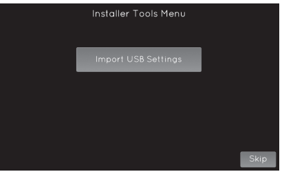
- If you have a USB drive with installer setup files on it, insert it into the USB connector (on the lower left corner) to import a file.
- Or press skip to proceed with the Installer Setup Wizard.
- Note: Installer setup files can be created from the Export Setup option found under Installer Menu > Installer Tools > Export Setup.
HVAC INSTALLER SYSTEM SETTINGS TABLES
The following tables contain the system settings and their details. Default settings are shown in bold. Some settings are only available dependent upon the value of other settings.
General System Settings Table
|
System setting |
Description |
Factory default setting (bold) and setting range |
| Connection Type | Selects if the thermostat connects with an automation system or an Aprilaire account . | Automation System
Aprilaire Cloud |
| Installer Temperature Scale | This selection only effects the installer setup menus . | Fahrenheit
Celsius |
| Contractor Information Input | Enter contractor’s contact information . | Company, Phone, Email, Web |
Thermostat System Settings Table
|
System setting |
Description |
Factory default setting (bold) and setting range |
| Equipment Type | Note: Equipment Type related settings will return to defaults if this is changed . | Heat/Cool
Heat Pump |
| Control Setup | Used to lockout heating or cooling outputs . (Heat/Cool mode only .) | Heat & Cool Heat Only Cool Only |
| Heat Pump Auxiliary Type | Selects auxiliary type . (Heat Pump mode only .) | Gas/Oil Heat
Electric Heat |
| Fan Control In Heating | Selects thermostat or equipment to control the fan in heating . (Heat/Cool mode only .) | Gas/Oil Heat
Electric Heat |
| Number of Compressor Stages | Select number of compressor stages . (Heat Pump mode only .) | One
Two |
| Number of Auxiliary Heat Stages | Select number of auxiliary heat stages . (Heat Pump mode only .) | One
Two |
| Number of Stages of Heat | Select number of heat stages . (Heat/Cool mode only .) | One Two Three |
| Number of Stages of Cool | Select number of cool stages . (Heat/Cool mode only .) | One Two Three |
| Remote Temperature Sensor Installed? | Select if the remote sensor is attached, and uses backup, or is averaged with built-in . | No
Yes Yes (fallback built-in) Yes (average w/built-in) |
| Return Air Temperature Sensor Installed? | Select if return air temperature sensor is attached or not . | No
Yes |
| Outdoor Temperature Sensor Installed? | Select if outdoor sensor is attached or not . | No
Yes Automation |
| Display Support Modules | Select if support module values are displayed on Monitored Climate screen under Status . | No
Yes |
| Number of Controlling Support Modules Temp | Select number of sensors configured to be controlling temperature . | 0-8 |
| Number of Controlling Support Modules RH | Select number of sensors configured to be controlling RH . | 0-4 |
| Schedule | Enables or disables programmable schedule . | Enabled
Disabled |
| Progressive Recovery | Enables or disables progressive recovery . | Enabled
Disabled |
| Display Away Button? | Away allows the user to set the thermostat to a predefined setpoint using a single button press .
The predefined setpoints can be selected in the User Settings . |
No
Yes |
| Display Heat Blast Button? | Select if the Heat Blast button is displayed . | No
Yes |
| Blast Offset | Amount of heating when Heat Blast is initiated . | 3°F (1.5°C)
4°F (2°C) 5°F (2 .5°C) |
|
System setting |
Description |
Factory default setting (bold) and setting range |
| Extended Fan – Heat | Extends fan operation after heat call ends . | Disabled
Enabled |
| Extended Fan – Cool | Extends fan operation after cool call ends . | Disabled
Enabled |
| Auto Changeover | Enable or disable Auto Changeover mode . | Disabled
Enabled |
| DeadBand | Auto Changeover mode deadband . | 3°F (1.5°C)
2 to 9°F (1 to 4 .5°C) |
| Auto Changeover Time | Minimum time between heating and cooling calls . | 4 Minutes
1 to 5 Minutes |
| Internal Temperature Sensor Offset | Field adjustment of controlling temperature sensors . | 0°F (0°C)
-4 to 4°F (-2 to +2°C) |
| Internal RH% Sensor Offset | Field adjustment of internal RH sensor . | 0
-5 to 5 |
| Equipment Minimum On Time | Minimum on time for heating and cooling . | 2 Minutes
1 to 5 Minutes |
| Heating Minimum Off Time | Minimum off time for heating . | 2 Minutes
1 to 5 Minutes |
| Compressor Minimum Off Time | Minimum off time for compressor protection . | 5 Minutes
1 to 5 Minutes |
| Outdoor Temperature High Balance Point | Enable or disable high balance point (Available if ODT is installed .) | Enabled
Disabled |
| Select High Temperature Balance Point | If outside temperature is above the high balance point the aux heat operation is not allowed . (Available if high balance point is enabled .) | 65°F (14.5°C)
0 to 80°F (-18 to 22°C) |
| Outdoor Temperature Low Balance Point | Enable or disable low balance point (Available if ODT is installed .) | Enabled
Disabled |
| Select Low Temperature Balance Point | If outside temperature is below the low balance point the compressor operation is not allowed . (Available if low balance point is enabled .) | 20°F (-8°C)
0 to 60°F (-18 to 12°C) |
| Stage Rate | Accumulation of equipment run time in staging determination . | Enabled
Disabled |
| Factor | 1 = more rapid staging of equipment (comfort), 5 = slower staging of equipment (economy) . | 2
1 to 5 |
| First Stage Differential | First stage differential . | 1°F (0.5°C)
1 to 9°F (0 .5 to 4 .5°C) |
| Second Stage Differential | Second stage differential . | 1°F (0.5°C)
1 to 9°F (0 .5 to 4 .5°C) |
| Third Stage Differential | Third stage differential . | 1°F (0.5°C)
1 to 9°F (0 .5 to 4 .5°C) |
| Fourth Stage Differential | Fourth stage differential . | 1°F (0.5°C)
1 to 9°F (0 .5 to 4 .5°C) |
| Service HVAC Reminder | The period for displaying the “HVAC Service reminder” message . | Disabled
Enabled |
| Number of Months for Recurrence | Select number of months for displaying reminder . | 12 Months
1 to 12 Months |
INDOOR AIR QUALITY SYSTEM SETTINGS TABLES
The following tables contain the Indoor Air Quality system settings and their details. Default settings are shown in bold. Some settings are only present dependent upon the value of other settings.
The use of an outdoor temperature sensor (recommended) enables additional Indoor Air Quality functionality.
Please refer to the Model 8840 Owner’s Manual for further information about thermostat features.
Note: Refer to manuals for humidifier, dehumidifier, air cleaner, and ventilation products for recommended installation and operation.
Humidifier System Settings Table
|
System setting |
Description |
Factory default setting (bold) and setting range |
| Humidifier Installed? | Selects if a humidifier is installed . (If set to No, no other humidifier settings will be available .) | No
Yes |
| Display Button? | Note: Only available if Humidifier Installed is set to No . | Yes
No |
| Outdoor Temperature Sensor Installed? | Select if outdoor sensor is attached or not . | No
Yes |
| Humidifier Mode | Auto: Controls based on setting and outdoor temperature . Manual: Controls based on RH% setpoint . (Auto mode is only available if Outdoor sensor is set to Yes .) | Automatic
Manual |
| Allowed Humidifier Operation | Selects when humidification is allowed to occur relative to heating and fan operation . | Heat Only Heat or Fan Forces Fan |
| Humidity Deadband | Select the minimum difference between the humidifier and dehumidifier setpoints . (Only available if both a humidifier and dehumidifier are installed .) | 10%
10 to 20% |
| Humidifier Reminder | Selects when the “Change Water Panel” message is displayed . | Off
300h Valve 600h Valve 1 per season 2 per season |
| Single or First Reminder Appears | Determines the month the first (or only) “Change Water Panel” message is displayed . | October November December January February March April
May June July August September |
| Second Reminder Appears | Determines the month the second “Change Water Panel” message is displayed . | October November December January February March April
May June July August September |
Dehumidifier System Settings Table
|
System setting |
Description |
Factory default setting (bold) and setting range |
| Dehumidifier Type Installed? | Selects if a dehumidifier is installed . (If set to None, no other dehumidifier settings will be available .) | None
Whole Home Air Conditioner |
| Display Button? | Note: Only available if Dehumidifier Installed is set to None . | Yes
No |
| Disable Dehumidification During Cooling? | Selects if a dehumidifier is disabled during a cooling call . | Yes
No |
| Dehumidifier Forces Fan? | Selects if dehumidification can turn on the fan . | Yes
No |
| Dehumidifier Overcooling Limit | Selects the amount of overcooling that can occur for dehumidification . (Only available if dehumidifier type is set to Air Conditioning .) | 1°F (0 .5°C)
2°F (1°C) 3°F (1.5°C) |
| Dehumidifier Reminder | The period for displaying the “Dehumidification Service Reminder” message . | Disabled
Enabled |
| Number of Months for Recurrence | Select number of months for displaying reminder . | 12 Months
1 to 12 Months |
| Dehumidify in Vacation Hold? | Selects if dehumidification with the air conditioner is done in vacation mode . | No
Yes |
| Vacation Hold Low Temperature Limit | Sets the lowest temperature the air conditioner will cool to, to meet RH setpoint in Vacation Mode . (Only available if dehumidifier type is set to Air Conditioning .) | 75°F (24°C)
70 to 85°F (21 to 29 .5°C) |
| Humidity Deadband | Select the minimum difference between the humidifier and dehumidifier setpoints . (Only available if both a humidifier and dehumidifier are installed .) | 10%
10 to 20% |
Air Cleaning System Settings Table
|
System setting |
Description |
Factory default setting (bold) and setting range |
| Air Cleaner Installed? | Selects if an air cleaner is installed . (If set to No, no other air cleaner settings will be available .) | No
Yes |
| Display Button? | Note: Only available if Air Cleaning Installed is set to No . | Yes
No |
| Air Cleaner Reminder | The period for displaying the “Change Air Filter” message . | Disabled
Enabled |
| Number of Months for Recurrence | Select number of months for displaying reminder . | 12 Months
1 to 12 Months |
Fresh Air System Settings Table
|
System setting |
Description |
Factory default setting (bold) and setting range |
| Fresh Air Installed? | Select if ventilation is installed . (If set to No, no other ventilation settings will be available .) | No
Yes |
| Display Button? | Note: only available if Fresh Air Installed is set to No . | Yes
No |
| Fresh Air Setup Type | ASHRAE: hourly ventilation time will be calculated using the ASHRAE recommendations . Timed: hourly ventilation time will be determined based on the Fresh Air Time value . | Timed
ASHRAE |
| Number of Bedrooms | Selects the number of bedrooms to be used for the ASHRAE calculation . | 3
1 to 6 |
| Number of Occupants | Selects the number of occupants to be used for the ASHRAE calculation . | 4
1 to 10 |
| Fresh Air Time | Selects how many minutes per hour that ventilation will be active in Timed setup type . | 30m
5 to 55m |
| Home Size | Selects the home size to be used for the ASHRAE calculation . | 2500 sqft
1000 to 5000 sqft |
| Fresh Air CFM Delivered | Selects the ventilation CFM to be used for the ASHRAE calculation . | 60 CFM
30 to 200 CFM |
| Indoor RH% High Limit | Selects if ventilation is disabled if the indoor RH exceeds the indoor RH limit . (Only available if Fresh Air Setup is set to Timed .) | Disabled
Enabled |
| RH% | Sets the high indoor RH limit for ventilation . (Only available if Fresh Air Setup is set to Timed .) | 60%
50 to 70% |
| Outdoor Temperature Sensor Installed? | Select if outdoor sensor is attached or not . | No
Yes |
| Calculated Minutes Per Hour | Displays the Fresh Air Time calculated by the ASHRAE standard . | 15 to 60 Minutes |
| Outdoor Temperature Low Limit | Selects if ventilation is disabled if the outdoor temperature exceeds the outdoor low limit . (Only available if an outdoor temperature sensor is installed .) | Disabled
Enabled |
| Temperature | Sets the low temperature limit for ventilation . (Only available if an outdoor temperature sensor is installed .) | 10°F (-12°C)
-10 to 40°F (-24 to 4 .5°C) |
| Outdoor Temperature High Limit | Selects if ventilation is disabled if the outdoor temperature exceeds the outdoor high limit . (Only available if an outdoor temperature sensor is installed .) | Disabled
Enabled |
| Temperature | Sets the high temperature limit for ventilation . (Only available if an outdoor temperature sensor is installed .) | 100°F (38°C)
90 to 105°F (32 to 40 .5°C) |
| Fresh Air Forces Fan | Selects if ventilation forces fan on . | Yes
No |
| Fresh Air Reminder | The period for displaying the “Fresh Air Service Reminder” message . | Disabled
Enabled |
| Number of Months for Recurrence | Select number of months for displaying reminder . | 12 Months
1 to 12 Months |
INSTALLER SYSTEM TEST
The Installer Test can be accessed from the Installer Menu. All equipment outputs that are configured in the installer settings can be turned on and off for testing equipment. Minimum on and off times are not enforced while in this mode.
WI-FI SETUP
The 8840 can be connected to a Wi-Fi network either at the thermostat or another Wi-Fi device with a web browser.
- STEP 1: Verify the thermostat is in Wi-Fi Connection Mode.
The thermostat by default will be in Wi-Fi Connection Mode. To confirm that the thermostat is in Wi-Fi Connection Mode, verify that the radio bars on the thermostat are strobing as shown below.
Note: If the thermostat is not in Wi-Fi Connection Mode, refer to the online owner’s manuals found at my.aprilaire.com.
CONNECT TO A NETWORK USING THE THERMOSTAT - STEP 2:
Navigate to the Connect without App screen: Menu > Wi-Fi Settings > Advanced > Connect without App. - STEP 3:
- Select a network from the list of scanned networks.
 STEP 4:
Enter a password and press Done.
- STEP 5:
Press Done on the Credentials screen to connect.
CONNECT TO A NETWORK USING A BROWSER
- STEP 2: Connect to the thermostat using a computer or mobile device.
- On your computer or mobile device, scan for available networks. The thermostat should appear as APRILAIRE8840 followed by a unique identifier, corresponding to the last 6 digits of the MAC address. Connect to the thermostat you want to configure.
- If you are installing multiple thermostats, the MAC address of each thermostat will be displayed on the Wi-Fi Settings screen, and can be found on the back of the thermostat.
- STEP 3: Configure the thermostat to connect to the Wi-Fi network.
- Open a web browser on your computer or mobile device. In the browser enter: http://192.168.1.99/index.html
- In the web browser interface select the network you want to connect the thermostat to, and enter the network’s security credentials.
- STEP 4: Verify the thermostat is connected to the Wi-Fi network.
- Once all the required information is entered in the web browser interface, the thermostat will connect to the Wi-Fi network you selected. After the thermostat is connected to the Wi-Fi network, the thermostat will display the radio bars based on the Wi-Fi signal strength.
- Note: If you are not using the thermostat with a home automation system, but are instead using an Aprilaire account to communicate with the thermostat, refer to Wi-Fi Thermostat App User Guide and then Start-Up Guide on my.aprilaire.com for instructions on connecting to Wi-Fi and registering to an Aprilaire account.
QUICK REFERENCE TO CONTROLS & DISPLAY
HOME SCREEN
MAIN MENU
INSTALLER MENU
EQUIPMENT CONTROL MODULE LEDs
- POWER/STATUS – On solid during normal operation. Flashes when connection to the thermostat is lost and at power-up while the thermostat connection is being established.
- HEATING – On when heating outputs are active.
- COOLING – On when cooling outputs are active.
- FAN – On when fan output is active.
- HUMIDIFIER – On when humidifier output is active.
- DEHUMIDIFIER – On when dehumidifier output is active.
- VENTILATION – On when ventilation output is active.
- AIR CLEANING – On when air cleaner output is active.
THERMOSTAT FEATURES
- Remote access and control over Wi-Fi.
- Indoor air quality control.
- Humidification automatic or manual control.
- Dehumidification.
- Event-Based™ air cleaning.
- Ventilation with temperature and humidity limits.
- Temperature control.
- Heat Blast® raises the room temperature 3°F to 5°F.
- One touch Away.
- Support for optional wireless outdoor temperature sensor.
- Large touch screen with adjustable backlight.
- 7 day programmability.
- Displays room temperature, room humidity, temperature setting, and optional outdoor temperature.
- Air filter, humidifier, dehumidifier, and HVAC service reminders.
- Programmable fan control with fan circulation mode.
- Easy to use temperature control can override program schedule at any time.
- Progressive recovery ensures proper temperature at the start of a program event.
- Built in compressor protection prevents damage to your equipment.
- System test mode.
TROUBLESHOOTING
DISPLAY IS BLANK
If Power LED is not illuminated at the equipment control module check the following:
-
Check circuit breaker and reset if necessary.
-
Make sure power switch at heating & cooling system is on.
-
Make sure furnace door is closed securely.
THE HEATING SYSTEM DOES NOT RESPOND (“HEATING” APPEARS ON SCREEN)
- Check for 24VAC at the equipment on the secondary side of the transformer between power and common. If voltage is not present, check the heating equipment to find the cause of the problem.
- Check for 24VAC between the heat terminal (W) and the transformer common. If 24VAC is present, the thermostat is functional. Check the heating equipment to find the cause of the problem.
- Check for loose or broken wires between the thermostat and the heating equipment.
THE COOLING SYSTEM DOES NOT RESPOND (“COOLING” APPEARS ON SCREEN)
- Check for 24VAC at the equipment on the secondary side of the transformer between power and common. If voltage is not present, check the cooling equipment to find the cause of the problem
- Check for 24VAC between the cooling terminal (Y) and the transformer common. If 24VAC is present, the thermostat is functional. Check the cooling system to find the cause of the problem.
- Check for loose or broken wires between the thermostat and the cooling equipment.
FAN DOES NOT TURN ON IN A CALL FOR HEAT
- Check Installer Setting Fan Control In Heating / Heat Pump Auxiliary Type, to make sure the fan control is properly set to match the type of system.
HEAT PUMP ISSUES COOL AIR IN HEAT MODE, OR WARM AIR IN COOL MODE
- Check wiring at the terminal block to confirm the reversing valve is connected to the proper terminal. O is active in cooling and B is active in heating.
HEAT/COOL BOTH ON AT SAME TIME
- Check Installer Setting Equipment Type, to make sure it is set to match the installed heating/cooling equipment.
- Check to make sure heating and cooling wires are not shorted together.
HEATING EQUIPMENT IS RUNNING IN COOL MODE
- Check Installer Setting Equipment Type, to make sure it is set to match the installed heating/cooling equipment.
“HEATING” IS NOT DISPLAYED
- Check Installer Setting Control Setup is set correctly.
- Change the System Mode to Heat, and set the temperature level above the current room temperature.
“COOLING” IS NOT DISPLAYED
- Check Installer Setting Control Setup is set correctly.
- Change the System Mode to Cool, and set the temperature level below the current room temperature.
SPECIFICATIONS
| Environment | |
| Temperature (shipping) | -30° to 150°F (-34° to 65°C) |
| Temperature thermostat (operating) | 32° to 120°F (0° to 48°C) |
| Temperature equipment control module (operating) | 32° to 158°F (0° to 70°C) |
| Relative humidity | Operating: 5% to 90% R .H . (non-condensing) |
| Electrical | |
| Operating voltage | 24VAC (18 – 30VAC) |
| Current | Maximum: 2 .5A (total), 1 .0A (single output) Maximum surge current: 5A |
| Control | |
| Outdoor, Remote, Leaving and Return temperature sensor | Maximum distance: 300 feet |
| Room temperature measurement | Display range: 32° to 99°F (0° to 40°C) |
| Return and Leaving temperature measurement | Display range: -40° to 160°F (-40° to 71°C) |
| Outdoor temperature measurement | Display range: -40° to 130°F (-40° to 55°C) |
| Setpoint temperature range | Heat: 40° to 90°F (4° to 32°C) Cool: 50° to 99°F (10° to 37°C) |
| Setpoint humidity range | Humidification: 10% to 50% R .H .
Dehumidification: 40% to 90% R .H . |
- P.O. Box 1467
- Madison, WI 53701-1467
- Phone: 800/334-6011
- Fax: 608/257-4357 www.aprilairepartners.com
- U.S. Patent Numbers 8,146,376, 8,596,078, and other patents are pending. © 2016 Aprilaire – A division of Research Products Corporation
REFERENCE
Download Manual:
Aprilaire 8840 Automation Thermostat Installation Instruction
other manuals:
Aprilaire 8840 Automation Thermostat Owner Manual
![]()
Aprilaire 8840 Automation Thermostat Installation Instruction