
Aprilaire 8476 Digital Programmable Thermostat with Wi-Fi

INSTALLATION
Thermostat should be mounted:
- On an interior wall, in a frequently occupied space.
- Approximately 5‘ above floor.
- At least 18” from outside wall.
- Thermostat can be mounted to a vertical junction box.
Do not mount thermostat:
- Behind doors, in corners, or other dead air spaces.
- In direct sunlight, near lighting fixtures, or other appliances that give off heat.
- On an outside or unconditioned area wall.
- In the flow of a supply register, in stairwells, or near outside doors.
- On a wall with concealed pipes or ductwork.
Outdoor temperature sensor (optional)
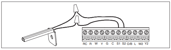
Outdoor temperature can be measured by attaching an 8052 sensor to the S1 and S2 terminals. System setting #05 (Remote sensor) is used to enable sensor. Heat pump applications can use the outdoor temperature to effectively utilize the heat pump:
- When the outdoor temperature is less than the Low Balance Point, the heat pump will be locked out and only auxiliary heating will be used.
- When the outdoor temperature is higher than the High Balance Point, the auxiliary heating will be locked out and only the heat pump will be used to provide heating
- Install on side of building out of direct sunlight (north side recommended).
- Mount above snow line.
- Mount at least 3’ away from exhaust vents and condensing lines.
- Maximum wire length is 300’.
- Do not route wires along 120 VAC lines.
Thermostat mounting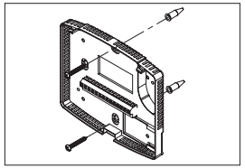
- Remove the back of the thermostat, by pressing the tab on the bottom of the unit.
- Pull wires through the opening on the back of the thermostat.
- Position and level the back of the thermostat on wall and mark the hole locations with a pencil.
- Drill 1/4” holes & insert supplied anchors (drywall only).
- Place back over anchors, insert and tighten screws.
- Seal wire entry holes to prevent drafts affecting temperature readings.
Power & Reset options
The thermostat is dual power. It can either be AC or battery powered, or both (to provide backup power for the clock). Batteries are optional if the thermostat was connected to AC power when installed. 24 VAC must be connected in order for the system fault and emergency heat indicators to operate.
The thermostat has a memory backup that saves the thermostat’s settings in case of a power interruption. The reset button located under the battery cover can be used to reset the thermostat back to factory defaults. The system settings will also be reset back to defaults.
Wiring terminal
Wire specifications
18-24 gauge thermostat wire Installation notes
- Ensure power at the HVAC equipment is off.
- Loosen screw terminals, insert stripped wire and re-tighten.
- Push the excess wire back into the opening and plug the wall opening to prevent drafts.
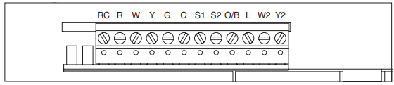
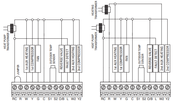
- RC – 24 VAC supply cooling*
- R – 24 VAC supply heating*
- W – 1st stage heat / auxiliary
- Y – 1st stage cooling / compressor
- G – Fan
- C – Common (optional when powered by batteries)
- S1 & S2 – outdoor temperature sensor (optional)
- O/B – Reversing valve
- L – System fault indicator
- W2 – 2nd stage heat / auxiliary
- Y2 – 2nd stage cooling / compressor
Jumper between RC & R is used in single transformer systems (see wiring diagrams).
Wiring – single Transformer
(use Jumper Wire) for HEAT/COOL System
Wiring – TWO TransformerS
(REMOVE Jumper Wire) for HEAT/COOL System
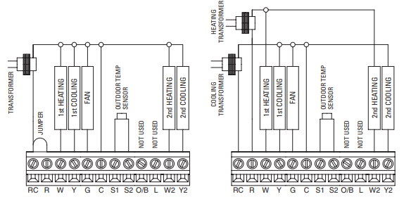
Wiring – single Transformer
(use Jumper Wire) for HEAT PUMP System
Wiring – TWO Transformers
(REMOVE Jumper Wire) for HEAT Pump System
Setup & Testing
System setup instructions
The following instructions show how to enter the system setup menu and change settings. The table on the following pages lists the settings and their details. Default settings are shown in bold. Some settings are only available based on other setting values.
How to enter the system setup menu to change system settings
- Press
 repeatedly until system is set to OFF.
 - Press and hold
 and for three seconds.
 - The screen of the first setting will be displayed.
- Press or
 to change the setting.
 - Press to change to the next option.
- Pressafter the last setting. “DONE” will be displayed.
- The thermostat will return to Normal mode if no button is pressed in 3 seconds.
- To reset all system settings back to default, press the RESET button located under the battery door.
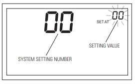
The Model 8476 thermostat has the option of being used in heat pump or heat/cool systems. Switch SW1 located on the back of the thermostat’s face is used to select this. System setting number 00 will only be shown on these models to display the position of SW1.
| System setting | Setting range, default in bold | |
| 00 | Equipment type (Set by Sw1) | 0 : heat/cool 1 : heat pump |
| 01 | Temperature scale | 0 : fahrenheit
1 : Celsius |
| 02 | Fan control in heating | 0 : gas or oil furnace (Equipment controls fan)
1 : Electric (Thermostat controls fan) |
| 03 | Offset temperature for internal sensor | 0° : No offset applied
–4°F to +4°F (–2°C to +2°C) |
| 04 | Auto mode | 0 : Auto mode is disabled
1 : Auto mode is enabled |
| 05 | Outdoor temperature sensor | 0 : No outdoor temperature sensor attached
1 : Outdoor temperature sensor attached |
| 06 | Compressor minimum off time | 5 minutes
1 to 5 minutes in 1 minute steps |
| 07 | Heating minimum off time | 2 minutes
1 to 5 minutes |
| 08 | Equipment minimum on time | 2 minutes
1 to 5 minutes |
| System setting | Setting range, default in bold |
| 09 1st stage differential | 1°f (0.5°C)
1°F to 4°F (0.5°C to 2°C) |
| 10 2nd stage differential | 1°f (0.5°C)
1°F to 4°F (0.5°C to 2°C) |
| 11 3rd stage differential (heat pump only) | 1°f (0.5°C)
1°F to 4°F (0.5°C to 2°C) |
| 12 Reverse valve (heat pump only) | 0 – O/B energized in cooling (O)
1 – O/B energized in heating (B) |
| 13 Integral factor period (P+I control)*
Set to OFF for proportional control only |
4 minutes
1 to 5 minutes or “OFF” to disable |
| 14 Deadband (auto mode) | 3°f (2°C)
2°F to 5°F (1°C to 3°C) |
| 15 Progressive recovery | 0 : Progressive recovery is disabled
1 : progressive recovery is enabled |
Note: The integral factor is used in the equipment control algorithm to maintain the space temperature at set point. A short integral factor period will increase the number of cycles per hour. (A short integral factor period will be more comfortable.) A long integral factor period will lower the number of cycles per hour. (A long integral factor period will be more economical.)
| System setting | Setting range, default in bold |
| 16 Low Balance Pt. (heat pump only)
System setting 05 must be enabled |
20°f (–7°C)
1°F to 35°F (–17°C to 1°C) or “OFF” to disable |
| 17 High Balance Pt. (heat pump only)
System setting 05 must be enabled |
60°f (16°C)
40°F to 80°F (4°C to 27°C) or “OFF “ to disable |
| 19 Program format | 0 – 5/2 program (weekdays and weekends)
1 – 5/1/1 program (Weekdays, Sat. and Sun.) |
| 20 Change air filter | Off
1, 3, 6, 12 months or “OFF” to disable |
| 21 Change water panel**
Set number of months until reminder is required |
Off
1 to 12 months or “OFF” to disable |
| 22 Humidifier type** | 0 : flow through type humidifier (1 reminder per season)
1 : Drain-less type humidifier (2 reminders per season) |
Note: If humidifier type is set to Drain-less, then the first reminder is based on the system setting 21, second reminder will activate 3 months later. If humidifier type is set to Flow through, then the first reminder is based on system setting 21, second reminder will activate 12 months later.
SYSTEM TEST MODE
The system test mode is used to test a system after installation. The outputs of the thermostat can be manually activated one at a time to test their function. The following instructions show how to enter the test mode and turn outputs on and off. The charts on the following pages show the output status for each test step for Heat/Cool and Heat Pump mode.
The test steps are:
| Test Number | Heat/Cool | Heat pump |
| 50 | Heating (W) (W2) | Aux Heating (W) (W2) |
| 51 | Cooling (Y) (Y2) | Compressor Cooling (Y) (Y2) |
| 52 | Fan (G) | Compressor Heating (Y) (Y2) |
| 53 | Fan (G) |
How to enter the system test menu
- Press repeatedly until system is set to OFF.
- Press and hold and
 for three seconds.
The screen of the first test step #50 is displayed:
- Press to turn on the output (01). For multi stage output, press again to turn on the 2nd stage (02).
- Press to turn off the output (00).
- Press to change to the next test step.
- Press after the last test step. “DONE” will be displayed.
The thermostat will return to Normal mode if no button is pressed in 3 seconds.
| Test steps for Heat/Cool | |||||||||
|
Step |
Key Input |
System Setting | Display (Output) | ||||||
|
#2 |
01
HEATINg ON (w) |
02
HEATINg ON (w2) |
01
COOlINg ON (Y) |
02
COOlINg ON (Y2) |
01 fAN ON
(g) |
||||
|
#50 Heat |
1st [UP] | 0 : Gas | ON | ||||||
| 1 : Elec | ON | ON | |||||||
| 2nd [UP] | 0 : Gas | ON | ON | ||||||
| 1 : Elec | ON | ON | ON | ||||||
| [DOWN] | |||||||||
|
#51 Cool |
1st [UP] | ON | ON | ||||||
| 2nd [UP] | ON | ON | ON | ||||||
| [DOWN] | |||||||||
| #52 Fan | [UP] | ON | |||||||
| [DOWN] | |||||||||
| Test steps for Heat pump | |||||||||
|
Step |
Key Input |
System Setting | Display (Output) | ||||||
|
#2 |
#12 |
01 AUX HEATINg ON (w) | 02 AUX HEATINg ON (w2) | 01
COOl/HEAT ON (Y) |
02
COOl/HEAT ON (Y2) |
01 fAN ON
(g) |
O/B |
||
|
#50 Aux |
1st [UP] | 0 : Gas | ON | ||||||
| 1 : Elec | ON | ON | |||||||
| 2nd [UP] | 0 : Gas | ON | ON | ||||||
| 1 : Elec | ON | ON | ON | ||||||
| [DOWN] | |||||||||
|
#51 Cool |
1st [UP] | 0 : O | ON | ON | ON | ||||
| 1 : B | ON | ON | |||||||
| 2nd [UP] | 0 : O | ON | ON | ON | ON | ||||
| 1 : B | ON | ON | ON | ||||||
| [DOWN] | 0 : O | ON | |||||||
| 1 : B | |||||||||
|
#52 Heat |
1st [UP] | 0 : O | ON | ON | |||||
| 1 : B | ON | ON | ON | ||||||
| 2nd [UP] | 0 : O | ON | ON | ON | |||||
| 1 : B | ON | ON | ON | ON | |||||
| [DOWN] | 0 : O | ||||||||
| 1 : B | ON | ||||||||
| #53 Fan | [UP] | ON | |||||||
| [DOWN] | |||||||||
QUICK REFERENCE TO CONTROLS & DISPLAY
THERMOSTAT FEATURES
- Event-Based™ Air Cleaning.
- Large, clear, backlit display is easy to read – even in the dark.
- Displays room temperature, temperature setting, and optional outdoor temperature.
- Dual power option (Battery or 24 VAC).
- Front battery door access for fast, easy replacement.
- Built in compressor protection.
- Water panel and air filter service indicators.
- System test mode.
- Separately programmable weekday/weekend schedules.
- Easy to use temperature control can override program schedule at any time.
- Progressive recovery. Progressive Recovery feature allows the thermostat to activate the heating and cooling equipment prior to an event in order to reach the desired temperature at the start of the next scheduled event.
TROUBLESHOOTING
DISPLAY IS BLANK
- Check circuit breaker and reset if necessary.
- Make sure power switch at heating & cooling system is on.
- Make sure furnace door is closed securely.
- If thermostat is battery powered, make sure fresh AA alkaline batteries are correctly installed.
TEMPERATURE SETTINGS DO NOT CHANGE
Make sure heating and cooling temperatures are set to acceptable ranges:
- Heat: 45° to 90°F (7° to 32°C).
- Cool: 50° to 99°F (10° to 37°C).
HEATING SYSTEM DOES NOT RESPOND (“HEATING” APPEARS ON SCREEN)
- Check for 24 VAC at the equipment on the secondary side of the transformer between power and common. If voltage is not present, check the heating equipment to find the cause of the problem.
- Check for 24 VAC between the heat terminal (W) and the transformer common. If 24 VAC is present, the thermostat is functional. Check the heating equipment to find the cause of the problem.
- Check for loose or broken wires between the thermostat and the heating equipment.
COOLING SYSTEM DOES NOT RESPOND (“COOLING” APPEARS ON SCREEN)
- Check for 24 VAC at the equipment on the secondary side of the transformer between power and common. If voltage is not present, check the cooling equipment to find the cause of the problem.
- Check for 24 VAC between the cooling terminal (Y) and the transformer common. If 24 VAC is present, the thermostat is functional. Check the cooling system to find the cause of the problem.
- Check for loose or broken wires between the thermostat and the cooling equipment.
FAN DOES NOT TURN ON IN A CALL FOR HEAT
Check System Setting #02 (Fan Control), to make sure the fan control is properly set to match the type of system (see page 11).
HEAT PUMP ISSUES COOL AIR IN HEAT MODE, OR WARM AIR IN COOL MODE
Check System Setting #12 (Reversing Valve), to make sure it is properly configured for your system (see page 12).
HEAT/COOL BOTH ON AT SAME TIME
- Check SW1 (Equipment Type), to make sure it is set to match the installed heating/cooling equipment (see page 11).
- Check to make sure heating and cooling wires are not shorted together.
HEATING EQUIPMENT IS RUNNING IN COOL MODE
Check SW1 (Equipment Type), to make sure it is set to match the installed heating/cooling equipment (see page 11).
“HEATING” IS NOT DISPLAYED
Change the System Mode to Heat, and set the temperature level above the current room temperature.
“COOLING” IS NOT DISPLAYED
Change the System Mode to Cool, and set the temperature level below the current room temperature.
SPECIFICATIONS
| Environment | |
|
Temperature |
Operating: 32° to 120°F (0° to 48.9°C) Shipping: -30° to 140°F (-34.4° to 60°C) |
| Relative humidity | Operating: 5% to 90% R.H. (non-condensing) |
| Electrical | |
| Operating voltage | 24 VAC (18 – 30 VAC) |
|
Current |
Maximum: 2.5A (total), 1.0A (single output) Maximum surge current: 5A |
|
Power supply |
Dual power. Can be battery or 24 VAC powered.
When both the sources are available, battery will be used as back up power . |
|
Battery power |
Battery power: AA size alkaline battery x 2 Battery life: Approximately 1 year |
| Thermal | |
| Outdoor temperature sensor | Maximum distance: 300 feet |
| Room temperature measurement | Display range: 32° to 99°F (0° to 40°C) |
| Outdoor temperature measurement | Display range: -20° to 130°F (-30° to 55°C) |
|
Temperature setting range |
Heat: 45° to 90°F (7° to 32°C) Cool: 50° to 99°F (10° to 37°C) |
P.O. Box 1467 Madison, WI 53701-1467
Phone: 800/334-6011
Fax: 608/257-4357
www.aprilairepartners.com
Patent Pending
© 2011 Aprilaire – A division of Research Products Corporation
References:
Download Manual
Aprilaire 8476 Digital Programmable Thermosta with Wi-Fi Safety & Installation Instructions
OTHER MANUAL
Aprilaire 8476 Digital Programmable Thermosta with Wi-Fi Owner Manual
Aprilaire 8476 Digital Programmable Thermostat with Wi-Fi Safety & Installation Instructions