
AMANA 2246007 Non-Programmable Electronic Thermostat
FEATURES
- Configurable
- 2-Stage Heat/2-Stage Cool Systems
- 2-Stage Heat Pump Systems
- Large Display With Backlight
- Selectable Fahrenheit or Celsius
- Compatible with Gas, Oil, or Electric
- Relay Outputs (minimum voltage drop in thermostat)
- Remote Sensor Compatible
- Ideally Suited for:
- Residential (New Construction/Replacement)
- Light Commercial
Parts Diagram

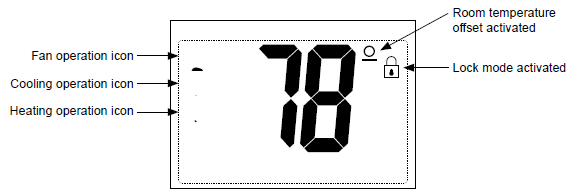
Icon Descriptions
Specifications
- Electrical rating: • 24 VAC (18-30 VAC)
- 1 amp maximum per terminal
- 3 amp maximum total load
- Temperature control range: 45°F to 90°F (7°C to 32°C) Accuracy: ± 1°F (± 0.5°C)
- System configurations: 2-stage heat, 2-stage cool, heat pump, gas, oil, electric
- Timing: Anti-short Cycle: 4 minutes (bypass anti-short cycle delay by returning to OFF mode for 5 seconds)
- Backlight Operation: 10 seconds
- Terminations: S1, S2, R, C, W/O/B, Y1, W2, Y2, G
Important Safety Information
WARNING!: Always turn off power at the main power supply before installing, cleaning, or removing thermostat.
- This thermostat is for 24 VAC applications only; do not use on voltages over 30 VAC
- Do not short across terminals of gas valve or system control to test operation; this will damage your thermostat and void your warranty
- All wiring must conform to local and national electrical and building codes
- Do not use air conditioning when the outdoor temperature is below 50 degrees; this can damage your A/C system and cause personal injuries
- Use this thermostat only as described in this manual
Package Contents/Tools Required
- Package includes: Amana® 2246007 thermostat on base, thermostat cover, wiring labels, screws and wall anchors, Installation, Operation and Application Guide
- Tools required for installation: Drill with 3/16” bit, hammer, screwdriver
To Remove Existing Thermostat
ELECTRICAL SHOCK HAZARD: Turn off power at the main service panel by removing the fuse or switching the appropriate circuit breaker to the OFF position before removing the existing thermostat.
- Turn off power to the heating and cooling system by removing the fuse or switching the appropriate circuit breaker off.
- Remove cover of old thermostat. This should expose the wires.
- Label the existing wires with the enclosed wire labels before removing wires.
- After labeling wires, remove wires from wire terminals.
- Remove existing thermostat base from wall.
- Refer to the following section for instructions on how to install this thermostat.
To Install Thermostat
ELECTRICAL SHOCK HAZARD: Turn off power at the main service panel by removing the fuse or switching the appropriate circuit breaker to the OFF position before removing the existing thermostat.
IMPORTANT: Thermostat installation must conform to local and national building and electrical codes and ordinances.
Note: Mount the thermostat about five feet above the floor. Do not mount the thermostat on an outside wall, in direct sunlight, behind a door, or in an area affected by a vent or duct.
- Turn off power to the heating and cooling system by removing the fuse or switching the appropriate circuit breaker off.
- To remove cover, pull gently at the seam at the top.
- Put thermostat base against the wall where you plan to mount it (Be sure wires will feed through the wire opening in the base of the thermostat).
- Mark the placement of the mounting holes.
- Set thermostat base and cover away from working area.
- Using a 3/16” drill bit, drill holes in the places you have marked for mounting.
- Use a hammer to tap supplied anchors in mounting holes.
- Align thermostat base with mounting holes and feed the control wires through slit in thermal intrusion barrier and into wire opening.
- Use supplied screws to mount thermostat base to wall.
- Insert stripped, labeled wires in matching wire terminals.
- CAUTION!: Be sure exposed portion of wires does not touch other wires.
- Gently tug wire to be sure of proper connection. Double check that each wire is connected to the proper terminal.
- Turn on power to the system at the main service panel.
- Configure thermostat to match the type of system you have.
- Replace cover on thermostat by snapping it in place.
- Test thermostat operation as described in “Testing the Thermostat”.
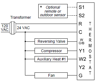
Wiring Diagrams
Heat/Cool Systems

- outdoor sensor only reads outdoor temperature
Single Compressor heat pump with electric backup
Dual Compressor heat pump with electric backup
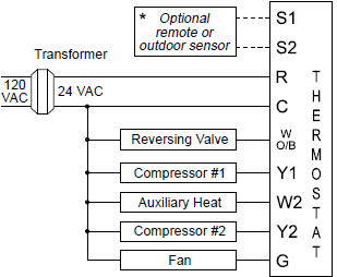
- outdoor sensor only reads outdoor temperature
Remote Sensor Installation (Optional)

- Remove cover from remote sensor housing.
- Select an appropriate location for mounting the remote sensor.
- Mount remote sensor unit using hardware provided.
- Install two strand shielded wire between remote sensor and thermostat. Shielded wire must be used. Do not run remote sensor wire in conduit with other wires.
- Wire 1 should run between the S1 terminal on the thermostat and the S1 terminal on the remote sensor
- Wire 2 should run between the S2 terminal on the thermostat and the S2 terminal on the remote sensor
- Connect the shielding of the wire to the S2 terminal on the thermostat
- Configure the thermostat to operate with the remote indoor sensor (see Configuration Mode setting) or use it for an outdoor sensor.
Note: Remote or outdoor sensor reading can be displayed by simultaneously pressing the Down and SYS buttons.
Terminal Designator Descriptions
- R: 24 VAC hot
- C: 24 VAC common
- W1/O/B: Configurable
- W1: 1st stage heat for non-heat pump systems
- O: cool active reversing valve
- B: heat active reversing valve
- Y1: 1st stage cool, 1st stage heat for heat pumps
- W2: 2nd stage heat for non-heat pump systems
- Y2: 2nd stage cool for 2 compressor systems, 2nd stage heat for 2 compressor heat pump systems
- G: Fan
Amana® 2246007 Output Chart
| 1ST Cool | 2ND Cool | 1ST Heat | 2ND Heat | |
| Heat/Cool | Y1, G | YI, Y2, G | W1, G* | W1, W2, G* |
| Heat Pump (One Compressor) | Y1, G, O | Y1, G, O | Y1, G, B | Y1, W2, G, B |
| Heat Pump (Two Compressors) | Y1, G, O | Y1, Y2, G, O | Y1, G, B | Y1, Y2, G, B |
| Electric Heat (Heat Pump Only) | N/A | N/A | W2, G | W2, G |
- G not energized when configured as a gas/oil system
The Amana® 2246007 thermostat is configurable for all systems. The configuration directly affects the outputs. Use the output chart to correctly configure and wire the thermostat to your system.
Modes Settings
The configuration mode is used to set the Amana® 2246007 to match your heating/cooling system. The Amana® 2246007 functions with heat pump, air conditioning, gas, oil or electric heat systems. To configure the Amana® 2246007, perform the following steps:

- Verify the Amana® 2246007 is in the OFF mode.
- Press the SYS (left) button until off mode displays.
- Remove the cover of the thermostat by gently pulling near one of the corners at the top of the thermostat.
- Press the CONFIG button for 1 second while the Amana® 2246007 is in OFF mode.
Press the up or down button to change settings within each screen.
Press the right button to advance to the next screen.
Note: Pressing the left button will return you to the previous screen.
To exit configuration mode, press the CONFIG switch for 1 second.
Configuration Mode Settings
The setup screens for Configuration Mode are as follows:
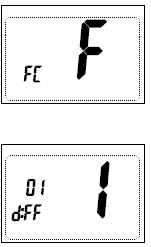
- Temperature Scale (F or C)
- Choose Fahrenheit or Celsius.
- Press the up or down button to select.
- Press the right button to advance to the next screen.
- 1st Stage Temperature Differential (1°F to 5°F) (0.5°C to 2.5°C)
- Set the number of degrees between your “setpoint” temperature and your “turn on” temperature.
- Press the up or down button to set differential value.
- Press the right button to advance to the next screen.
- 2nd Stage Temperature Differential (1°F to 5°F) (0.5°C to 2.5°C)
- Set the number of degrees between when stage 1 turns on and when stage 2 turns on.
- Press the up or down button to set differential value.
- Press the right button to advance to the next screen.
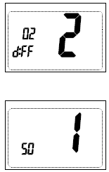
- Staged Off Outputs
- Select whether the outputs for heating and cooling are staged off independently or are satisfied simultaneously.
- 1 = outputs staged off independently
- 0 = outputs off simultaneously
- Press the up or down button to set.
- Press the right button to advance to the next screen.
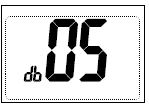
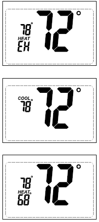
- Minimum Deadband (1°F to 9°F) (1°C to 5°C)
- Set the minimum separation between heat setpoint and cool setpoint in Auto Changeover Mode.
- Press the up or down button to set deadband value.
- Press the right button to advance to the next screen.
- System: Set for heat pump, non-heat pump, reversing valve operation and number of compressors in your system.
Choose
System
Reversing Valve Active Number of Compressors or Compressor Stages Type of Heat Heat Pump
HP O 1 HP b 1 HP O 2 HP b 2 Non-Heat Pump Heat Gas Heat Electric - Press the up or down button to select.
- Press the right button to advance to the next screen.
- Press the up or down button to select.
- Auxiliary Delay ON – (0-30 minutes)
- Set the delay time in minutes for auxiliary heat to be locked out after a call for second stage. This extra savings feature is used to temporarily lock out auxiliary heat devices, allowing just heat pump to try to satisfy heat call.
- Press the up or down button to select.
- Press the right button to advance to the next screen.
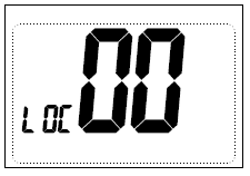
- Lockout (0-8°, COOL-HEAT)
- Select the number of degrees set temperature can be changed during keypad lockout.
- COOL-HEAT lockout allows adjustment of the set temperatures to the maximum heat set temperature selected in Step 9 and minimum cool set temperature selected in Step 10.
- Note: The mode cannot be changed when the thermostat is locked.
- Press the up or down button to select.
- Press the right button to advance to the next screen.
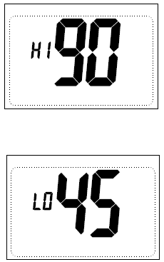
- Maximum Heat Setpoint (45°F to 90°F) (7°C to 32°C)
- Adjust to control the maximum heat set temperature allowed.
- Press the up or down button to select.
- Press the right button to advance to the next screen.
- Minimum Cool Setpoint (45°F to 90°F) (7°C to 32°C)
- Adjust to control the minimum cool set temperature allowed.
- Press the up or down button to select.
- Press the right button to advance to the next screen.
- Room Temperature Offset (+9°F to -9°F) (+4.5°C to -4.5°C)
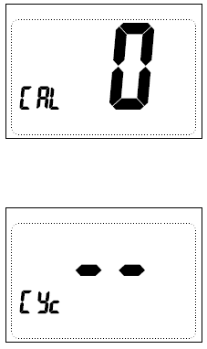
- Adjust to calibrate displayed room temperature to match actual room temperature.
- Note: When not set to 0, will display.
- Press the up or down button to select.
- Press the right button to advance to the next screen.
- Maximum Cycles Allowed Per Hour (- -, 2-6)
- – – = as many as needed, 2-6 = maximum cycles/hour
- Press the up or down button to select.
- Press the right button to advance to the next screen.
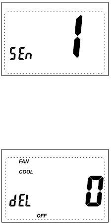
- Temperature Sensor (1-3)
- Only on-board sensor determines room temperature.
- Only remote sensor determines room temperature.
- Average temperature of on-board and remote sensor.
- Note: If there is no remote sensor, option 1 must be selected.
- Press the up or down button to select.
- Press the right button to advance to the next screen.
- Cooling Fan Delay Off Time (0, 30, 60, 90 seconds)
- Select the fan purge time for cooling.
- Press the up or down button to select.
- Press the right button to advance to the next screen.
Press the CONFIG button for 2 seconds to exit the configuration.
Mode of Operation
The Amana® 2246007 is an auto changeover, 2-stage heat, 2-stage cool thermostat. It functions with air conditioning, heat pumps, gas, oil or electric heat systems. An outdoor sensor can be used to monitor the outdoor temperature. The thermostat activates the heating appliance when the room temperature is below the set heat temperature (by the differential temperature). The Amana® 2246007 will stop outputting when the call for heat has been satisfied. With heat pumps, the thermostat will not let the compressor come on for 4 minutes after it turns off. This protects your compressor.
When the room temperature is greater than the set cool temperature (by the differential temperature), the cooling device is activated. The Amana® 2246007 will stop outputting when the call for cooling is satisfied. The thermostat will not let the compressor come on for 4 minutes after it turns off. This protects your compressor. The Amana® 2246007 has four possible operating modes: OFF, Heat, Cool, and Heat & Cool mode. In off mode, the thermostat will not turn on heating or cooling devices. The manual fan can be turned on in all operating modes using the fan button. In heat mode, the thermostat controls the heating system. In the cool mode, the thermostat controls the cooling system. In heat & cool mode, the thermostat controls both the heating and cooling systems. The Amana® 2246007 also has a button lockout feature. This enables the thermostat to be set to the proper mode and temperature and locked so it cannot be tampered with.

- UP: Used to increase the set temperatures and to adjust configuration settings.
- DOWN: Used to decrease the set temperatures and to adjust configuration settings.
- SYS (left): Used to change from OFF, HEAT, ELECTRIC HEAT, COOL and AUTO changeover modes
- FAN (right): Used to turn on and off the indoor fan.
- UP, SYS and FAN: Held in simultaneously for 10 seconds to lock and unlock the thermostat.
- DOWN and SYS: Pressed simultaneously to display outdoor temperature if outdoor remote sensor is connected.
Operating Modes
There are four possible operating modes for the Amana® 2246007. Off, Cool, Heat, and Cool & Heat modes are accessed by pressing the SYS (left) button.

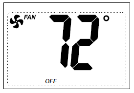
OFF Mode
- In this mode, the thermostat will not turn on the heating or cooling devices
- Note: The indoor fan can be turned on manually in every operating mode by pressing the FAN (right) button. The word FAN shows on the display and the fan icon
 appears when the fan operates.
- Note: The indoor fan can be turned on manually in every operating mode by pressing the FAN (right) button. The word FAN shows on the display and the fan icon
Heat Mode
- In this mode, the thermostat controls the heating system. When the heat outputs, the flame icon
 apprears on the display.
- Note: For heat pumps, there is a four minute delay for your compressor to restart after it has turned off. To bypass the compressor time delay, go to OFF mode for 5 seconds.
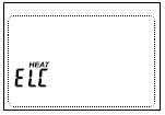
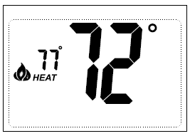
Electric Heat Mode (Heat pump systems only)
- In Electric Heat mode, the heat pump system will be disabled and auxiliary heat will become the primary source of heat.
Cool Mode
- In this mode, the thermostat controls the cooling system. When the cooling outputs, the snowflake icon
 apprears on the display.
- Note: There is a four-minute delay for your compressor to restart after it has turned off. To bypass the compressor time delay, go to OFF mode for 5 seconds.
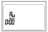
Cool and Heat Mode (Auto Changeover)
- In this mode, the thermostat controls the cooling and heating systems, automatically changing over from one to the other as needed.
- The timing display alternates with the set temperature every 10 seconds in the cool and heat mode.
Testing the Thermostat
Once the thermostat is configured, it should be thoroughly tested.
CAUTION!: Do not energize the air conditioning system when the outdoor temperature is below 50 degrees. It can result in equipment damage or personal injury.
Heat Test
- Press SYS (left) button until heat mode is displayed.
- Adjust the set temperature so it is 5 degrees above the room temperature.
- Heat should come on within a few seconds.
- Adjust the set temperature 2 degrees below the room temperature and the heat should turn off. There may be a fan delay on your system.
Note: For heat pumps, there is a four-minute delay to protect your compressor after it turns off. To bypass the compressor time delay, go to OFF mode for 5 seconds.
Cool Test

- Press SYS (left) button until cool mode is displayed.
- Adjust set temperature so it is 5 degrees below room temperature.
- A/C should come on within a few seconds.
- Adjust the set temperature 2 degrees above the room temperature and the A/C should turn off. There may be a fan delay on your system.
Note: There is a four-minute time delay to protect the compressor after it . To bypass the compressor time delay, go to OFF mode for 5 seconds.
Fan Test
- Press FAN (right) button. Fan displays. Indoor fan turns ON.
- Press FAN (right) button. Indoor fan turns OFF.
Lockout Feature
The Amana® 2246007 has a button lockout feature so the mode cannot be changed and the temperature adjustment is limited. Select the appropriate lockout from Configuration Mode Settings (Step 8) of this guide.
To activate the LOCK feature:
- Simultaneously press the SYS, FAN and UP buttons for 10 seconds.
 will display and the lockout function will be enabled.
To deactivate the LOCK feature, repeat steps 1 and 2 above.
Troubleshooting
| Symptom | Remedy |
| No display | Check for 24 VAC at thermostat; display is blank when 24 VAC is not present |
| System fan does not come on properly | Verify wiring is correct, check Gas/Electric Configuration (see Configuration Mode Setting 6) |
| All thermostat buttons are inoperative | Verify 24 VAC is present; unit locks out when 24 VAC is not present |
| No response with first button press | First button press activates backlight only |
| Thermostat turns on and off too frequently | Adjust temperature differential
(see Configuration Mode Settings 2 & 3) |
| Fan runs continuously | Press FAN (right) button to turn fan off |
| Room temperature is not correct | Calibrate thermostat (see Configuration Mode Setting 11)
If remote sensor is used, check S1 and S2 terminal connections |
| Thermostat has the button lockout function activated (see Lockout Feature and Configuration Mode Setting 8) | |
| Check for a bad connection at S1 and S2 terminals, if used (see Configuration Mode Setting 13) | |
| Heat or Cool not coming on | Verify wiring is correct, gently pull on each wire to verify there is a good connection at terminal block |
| Problem not listed above | Press Reset button once* |
Reset Button Function: Display is refreshed, configuration settings are unchanged.
Downloaded from www.Manualslib.com manuals search engine
Reference
Download Manual:
AMANA 2246007 Non-Programmable Electronic Thermostat Installation Guide
![]()
AMANA 2246007 Non-Programmable Electronic Thermostat Installation Guide
Leave a Reply