AMANA 2246002 Non-Programmable Electronic Thermostat
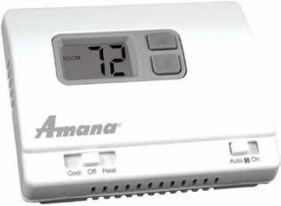
- Controls Single Stage Heating/ Cooling Systems
- Single Stage Heat Pump Systems
- Compatible with Gas, Oil or Electric Systems
- Millivolt and Hydronic (water or steam) System Compatible
- Mercury-Free, Environmentally Safe
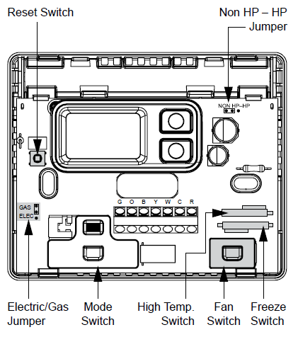
Parts Diagrams
Specifications
- Input:
- Voltage: 18-30 VAC
- Output:
- Maximum: 1 amp per terminal (3 amp total for all terminals)
- Temperature control ranges: 45°F to 90°F (7°C to 32°C)
- Accuracy: ± 1°F (± 0.5°C)
- Differential range: 1°F to 3°F (0.5°C to 1.5°C)
- System configurations:
- Single-stage heat, single-stage cool or single-stage heat pump, gas, oil, electric
- Terminations: R, W, Y, O, B, G, C
Important Safety Information
- Always turn off the thermostat before installing, removing, cleaning, or servicing; turn off the power at the main power source by unscrewing fuse or switching off circuit breaker
- Do not switch to “Cool” if room temperature is below 50°F (10°C); this could damage your A/C system and cause injury
- Do not install on voltages higher than 30 VAC
- All wiring must conform to local and national building and electrical codes and ordinances
- While cleaning, do not get soap directly on thermostat switches or LCD readout; only use a damp cloth with a mild soap to wipe outside of thermostat cover
Package Contents/Tools Required
- Package includes: Amana® 2246002 non-programmable thermostat on base, thermostat cover, wiring labels, screws and wall anchors, batteries (if applicable), Installation, Operation and Application Guide.
- Tools required for installation: Drill with 3/16” bit, hammer, screwdriver.
General Description
- The Amana® 2246002 thermostat is a digital, mercury-free, non-programmable, electronic thermostat
- Compatible with single-stage heating systems, heating/cooling systems, and heat pump systems; works with gas, oil, or electric systems
- Compatible as a master thermostat in zoned system applications
- Freeze Protection Feature: Protects pipes from freezing! If the room temperature drops to 40°F, the thermostat automatically turns on the heat; the thermostat must be in the Heat position; works even if the batteries are dead
- Built-in Compressor Protection for Air Conditioners: To protect the A/C’s compressor, there is a 5-minute delay between the system turning off and the A/C starting
- System Customization: Choose Fahrenheit or Celsius display; three available temperature differential settings
To Remove Existing Thermostat
ELECTRICAL SHOCK HAZARD: Turn off power at the main service panel by removing the fuse or switching the appropriate circuit breaker to the OFF position before removing the existing thermostat.
- Turn off power to the heating and cooling system by removing the fuse or switching off the appropriate circuit breaker.
- Remove cover of old thermostat. This should expose the wires.
- Label the existing wires with the enclosed wire labels before removing wires.
- After labeling wires, remove wires from wire terminals.
- Remove existing thermostat base from wall.
- Refer to the following section for instructions on how to install this thermostat.
To Install Thermostat
ELECTRICAL SHOCK HAZARD: Turn off power at the main service panel by removing the fuse or switching the appropriate circuit breaker to the OFF position before removing the existing thermostat.
IMPORTANT: Thermostat installation must conform to local and national building and electrical codes and ordinances.
Note: Mount the thermostat about five feet above the floor. Do not mount the thermostat on an outside wall, in direct sunlight, behind a door, or in an area affected by a vent or duct.
- Turn off power to the heating and cooling system by removing the fuse or switching off the appropriate circuit breaker. Move the Cool/OFF/Heat switch to OFF.
- Move the FAN AUTO/ON switch to AUTO.
- To remove cover, insert and twist a coin or screwdriver in the slots on the top of the thermostat.
- Put thermostat base against the wall where you plan to mount it (Be sure wires will feed through the wire opening in the base of the thermostat).
- Mark the placement of the mounting holes.
- Set thermostat base and cover away from working area.
- Using a 3/16” drill bit, drill holes in the places you have marked for mounting.
- Use a hammer to tap supplied anchors into mounting holes.
- Align thermostat base with mounting holes and feed the control wires through wire opening.
- Use supplied screws to mount thermostat base to wall.
- CAUTION: Be sure exposed portion of wires does not touch other wires.
- Tighten screws on the terminal block. Gently tug wire to be sure of proper connection. Double check that each wire is connected to the proper terminal.
- Set the fan jumper to electric or gas/oil, and heat pump jumper to NON-HP or HP.
- Replace cover on thermostat by snapping it in place.
- Turn on power to the system at the main service panel.
Replacing Wiring Labels
Replace the old labels with the enclosed new labels:
| Old | New | Type |
| F, G | G | Fan control relay |
| O | O | Cool active reversing valve |
| B | B | Heat active reversing valve |
| Y, Y6 | Y | Cooling control |
| H, W, 4 | W | Heating control |
| C | Transformer, common side | |
| M, 4, RH, RS, R | R | Transformer, hot side |
| C | Y or C | If the C terminal is the cooling control, connect to Y terminal; if it is the common side of the transformer, connect to C terminal |
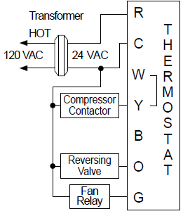
Wiring Diagrams
Heating and Cooling
- 4 or 5-Wire, Single Transformer
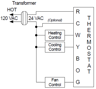
Heating Only
- 4-Wire, Single Transformer

- 3-Wire, Single Transformer

Heat Pump
- Cool Active Reversing Valve
- Heat Active Reversing Valve
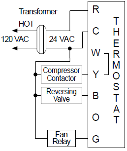
Place jumper between “W” and “Y” terminals.
Cool Only
- 4-Wire Single Transformer
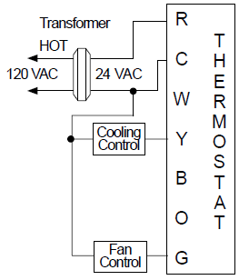
Millivolt systems may require a transformer and/or an isolation relay to operate properly.
A Quick Test
CAUTION!: Do not switch system to cool if the temperature is below 50°F (10°C). This can damage the air conditioning system and may cause personal injury.
Do not short jumper across terminals on the gas valve or at the system control to test installation.
- Action: Set the Cool/Off/Heat switch to Cool. Press the down button until the temperature setting is 3°F below the room temperature.
- Result: The A/C system and fan should turn on.
- Action: Set the Cool/Off/Heat switch to Off.
- Result: The A/C should turn off (There may be a fan delay).
- Action: Set the Cool/Off/Heat switch to Heat. Press the up button until the temperature setting is 3°F above the room temperature.
- Result: The heating system and fan should turn on (There may be a time delay depending on your system).
- Action: Set the Cool/Off/Heat switch to Off.
- Result: The heating system should turn off (There may be a fan delay).
- Action: Set the Fan Auto/On switch to On.
- Result: The blower fan should turn on.
- Action: Set the Fan Auto/On switch to Auto.
- Result: The blower fan should turn off.
- If the above test was successful, you have a proper installation.
- If not: Double check that wires are securely connected and are connected to the proper terminals. Consult the troubleshooting section.
Operation
Setting the Room Temperature (Setpoint Temperature)
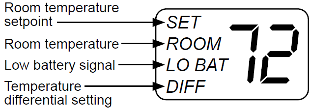
- Step 1: Press one of the arrow buttons; the current temperature setting displays.
- Step 2: Press the down or up or up arrow button until the desired temperature setting displays.
The new temperature setting is automatically saved. After 5 seconds, the display returns to showing the current room temperature.
Setting a New Temperature Differential
The default temperature differential is 1°. When your room temperature varies by 1°F, the thermostat turns your system on. If you notice your system turning on and off too frequently, increase the temperature differential.
- Step 1: Reset thermostat by pressing the Reset button once.
- Step 2: For the first 10 seconds of operation, the temperature differential is displayed.
- Press the down or up arrow button to select desired setting.
Starting the Thermostat
- Step 1: Move the Fan Auto/On switch into the Auto position.
- Step 2: Move the Cool/Off/Heat switch to Cool or Heat, depending on the season.
Troubleshooting
| Symptom | Remedy |
| The system isn’t turning on | Check the wiring (see Installation) |
| LCD is blank | Verify 24 VAC is at thermostat. |
| Thermostat is not properly controlling the fan | Check that the Gas/Electric jumper setting matches your system (gas or electric) |
| Thermostat is continuously turning on and off | Increase the temperature differential
(see Setting a New Temperature Differential) |
| Temperature displayed is not accurate | Plug the hole for wiring behind the thermostat with non-flammable insulation to prevent airflow into the thermostat |
Downloaded from www.Manualslib.com manuals search engine
Reference
Download Manual:
AMANA 2246002 Non-Programmable Electronic Thermostat Installation Guide

AMANA 2246002 Non-Programmable Electronic Thermostat Installation Guide