
AIRXCEL 9630-351 Thermostat

Application
The thermostat wiring is factory installed by the OEM (Original Equipment Manufacturer). RV Products suggests the thermostat wiring be a minimum of 18 gauge. The thermostat is intended for use with a 12 VDC control circuit that does not exceed 1 amp. The thermostat is equipped with a replaceable 2 amp fuse located on the base of the thermostat. The fuse is designed to “open” if the circuit is mis-wired or if there is a short in the system. Before replacing the fuse, the cause of the failure must be located and corrected.
Caution This thermostat should be installed by trained technicians only. Adhere to all local and national codes and ordinances. Disconnect all power to the system before installing, removing, or cleaning.
Operation
The display indicates the mode and the room temperature. When the mode button is pressed once, the thermostat will wake. If your thermostat is equipped with a backlight, the backlight will illuminate. When the mode button ![]() is pressed again, the mode will change. Press the
is pressed again, the mode will change. Press the![]() button to wake the thermostat; the set temperature will display and the mode will flash. Press the
button to wake the thermostat; the set temperature will display and the mode will flash. Press the![]() button again to change the set temperature. The thermostat will return to sleep mode after 5 seconds if no button is pressed.
button again to change the set temperature. The thermostat will return to sleep mode after 5 seconds if no button is pressed.
In electric heat mode, if the heat pump is unable to satisfy the thermostat call, the heat pump will go into lockout (See heat pump and backup heat example for conditions of heat pump lockout). When thermostat is in lockout, ELEC will flash on the display.
In gas heat mode, the gas furnace will provide the only source of heat and the heat pump is locked out.
| Temperature | ||
|
Mode |
Range | |
| °F | °C | |
| Cooling (set) | 33°F to 99°F | 1°C to 37°C |
| Heating (set) | 33°F to 99°F | 1°C to 37°C |
Refer to the operation chart for a more detailed listing of operation sequence.
Installation
ELECTRICAL SHOCK HAZARD – Turn off power at the main service panel by removing the fuse or switching the appropriate circuit breaker to the Off position before removing the existing thermostat.
A. THERMOSTAT LOCATION
This thermostat is a sensitive instrument. For accurate temperature control and comfort, the following considerations should be taken into account:
- Locate the thermostat on an inside wall about five feet above the floor. Pick a dry area where air circulation is good.
- Do not install thermostat where there are unusual heating conditions, such as direct sunlight, near heat producing appliances (televisions, radio, wall lamp, etc.), or a furnace or air conditioner supply register.
B. INSTALLING THE THERMOSTAT
- Place mounting screw template against the wall where thermostat will be mounted.
- Using supplied screws, mount the template to the wall.
- Remove plastic from between mounting screws.
- Connect thermostat wiring to motorcoach wiring.
- Place thermostat on mounting screws and gently push the thermostat down to lock the thermostat onto mounting screws.
- Turn on power to the thermostat.

Wiring Diagrams
Note: When used to replace a thermostat which previously did not use plugs, please remove the plugs and use wire nuts as needed.
 UP – Wake thermostat and increase temperature
 DOWN – Wake thermostat and decrease temperature
 MODE – Wake thermostat, change mode
Note: Hold mode button down for 5 seconds. The thermostat will change from fahrenheit to celsius or celsius to fahrenheit. The backlight will turn off after five seconds.
Pairing the Thermostat
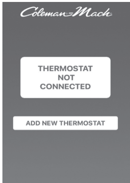
- Download the RV Climate app from either the Google Play store or Apple App store.
- Open the app and select “ADD NEW THERMOSTAT”.
- On the thermostat, hold the Up and Down buttons simultaneously to enter pair mode.
- On the App select “PAIR NEW THERMOSTAT”.
- When prompted, enter the 6 digit ID from the thermostat and select “PAIR”.
- Once connected the thermostat will revert to the main screen.
- Slide screen to the left (2nd screen).
- Press

- Select “ZONE NAME”.
- Assign a name or description to the thermostat (7 characters max).
- Select “SET” to save the assigned name or description.
Note: Each thermostat may be connected to a maximum of 4 individual phones. Any subsequent connections will result in the oldest/first connections being automatically deleted in order.
Pairing additional thermostats
- Using the RV Climate app.
- Slide screen to the left (last screen).
- Select “PAIR NEW THERMOSTAT”.
- On the thermostat, Hold the Up and Down buttons simultaneously to enter pair mode.
- When prompted, enter the 6 digit ID from the thermostat and select “PAIR”.
- Once connected the thermostat will revert to the main screen.
- Slide screen to the left (2nd screen).
- Press .
- Select “ZONE NAME”.
- Assign a name or description to the thermostat (max. of 7 characters).
- Select “SET” to save the assigned name or description.
Note: A maximum of 3 units may be added to an individual phone.
Pairing a previously paired thermostat
- Using the RV Climate app select “PAIR NEW THERMOSTAT”.
- On the thermostat, Hold the Up and Down buttons simultaneously to enter pair mode.
- Thermostat will automatically pair.
Note: If thermostat doesn’t pair automatically, when prompted enter the 6 digit ID from the thermostat and select “PAIR”. - Once pairing is complete, press the thermostat’s mode button to return to the main screen.
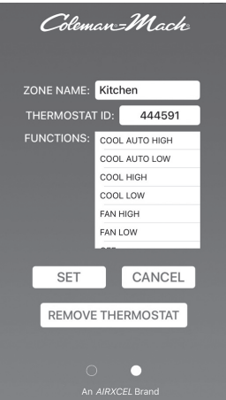
Details (2nd Screen)
ZONE NAME: Assigns a name or description to the thermostat (maximum of 7 characters).THERMOSTAT ID: Displays thermostat’s 6 digit ID
FUNCTIONS: Displays available modes. SET: Saves assigned zone name/ description.
CANCEL: Reverts to main screen.
REMOVE THERMOSTAT: Removes thermostat from the RV Climate app.
Controlling the thermostat via RV Climate app
- Slide screen to the left (2nd screen).
- Tap the icon displaying the current settings [Kitchen 75 FAN HIGH].
- Select the desired temperature/mode.
- Press “SET”.
Removing a previously paired thermostat
- Using the RV Climate app, slide screen to the left (2nd screen).
- Press

- On the following page select “REMOVE THERMOSTAT” and press “OK”.
Operation Chart
The chart below shows the system functions. After the entire air conditioning and heating system is installed, check each position function.
| Mode | Call | Operation |
| Fan Low | No | GL-Fan Low (Gray) energized |
| Fan Hi | No | GH-Fan High (Green) energized |
| Cool On High | No | GH-Fan High (Green) energized |
| Cool On High | Yes | GH-Fan High (Green) energized, Y-Compressor (Yellow) energized |
| Cool On Low | No | GL-Fan Low (Gray) energized |
| Cool On Low | Yes | GL-Fan Low (Gray), Y-Compressor (Yellow) energized |
| Cool Auto Low | No | No function occurs |
| Cool Auto Low | Yes | GL-Fan Low (Gray) energized, Y-Compressor (Yellow) energized |
| Cool Auto High | No | No function occurs |
| Cool Auto High | Yes | GH-Fan High (Green), Y-Compressor (Yellow) energized |
| Heat Gas | No | No function occurs |
| Heat Gas | Yes | W-Furnace (White) energized |
| Electric Heat | No | No functions occur in this mode |
| Electric Heat | Yes | WHP – Heat Pump (White/Black) will be energized |
| Electric Heat Backup | Yes (5° Below Setpoint) | WHP – Heat Pump (White/Black) and WF-Furnace (White) will be energized |
Conditions of Heat Pump Lockout (Set Point 70°F)
| Indoor Temp (°F) | Operation of Unit |
| 70+ | No operation. |
| 69 | Heat pump turns on as primary heat source. |
| 71 | Heat pump turns off, thermostat is satisfied. |
| 69 | Heat pump turns on as primary heat source. |
| 65 | Gas heat turns on at 5 degrees from first stage (heat pump cannot satisfy demand). First Strike on backup counter. |
| 71 | Gas heat and heat pump turn off, thermostat is satisfied. |
| 69 | Heat pump turns on. |
| 65 | Gas heat turns on at 5 degrees below first stage (heat pump cannot satisfy demand). Second Strike on backup counter. |
| 71 | Gas heat and heat pump turn off, thermostat is satisfied. |
| 69 | Heat pump turns on. |
| 65 | Gas heat turns on at 5 degrees from first stage (heat pump cannot satisfy demand).
Third Strike on backup counter. Heat pump is locked out for 1 hr. 45 min. |
| Backup counter reset if heat pump runs for 20 minutes with no call for back up heat. | |
| 71 | Gas furnace turns off, thermostat is satisfied. |
| 69 | Gas furnace turns on, primary heat source during lockout. |
| 71 | Gas furnace turns off, thermostat is satisfied. |
| 1 hour 45 minute lockout ends. | |
| 69 | Heat pump turns on and is restored to the primary heat source. |
| 65 | Gas furnace turns on and becomes the primary heat source. Heat pump turns off for another 1 hour and 45 minutes. |
| 71 | Gas furnace turns off, thermostat is satisfied. |
| 1 hour 45 minute lockout ends. | |
| 69 | Heat pump turns on and resumes primary heat source function. |
| 71 | Heat pump turns off, thermostat is satisfied. |
| Conditions and example for resetting the backup counter | |
| 69 | Heat pump turns on. |
| 65 | Gas heat turns on at 5 degrees from first stage (heat pump cannot satisfy demand).
First Strike on backup counter. |
| 71 | Gas heat and heat pump turn off, thermostat is satisfied. |
| 69 | Heat pump turns on. |
| 65 | Gas heat turns on at 5 degrees from first stage (heat pump cannot satisfy demand).
Second Strike on backup counter |
| 71 | Gas heat and heat pump turn off, thermostat is satisfied. |
| 69 | Heat pump turns on and runs for 20 minutes without a call for backup heat. |
| 71 | Heat pump turns off, thermostat is satisfied (backup counter reset). |
| 69 | Heat pump turns on. |
| 65 | Gas heat turns on at 5 degrees from first stage (heat pump cannot satisfy demand).
First strike on backup counter |
| Backup timer will reset anytime the Heat Pump operates for more than 20 minutes and satisfies the thermostat without calling for backup heat. | |
This device complies with part 15 of the FCC Rules. Operation is subject to the following two conditions: (1) This device may not cause harmful interference, and (2) this device must accept any interference received, including interference that may cause undesired operation.
NOTE: This equipment has been tested and found to comply with the limits for a Class A digital device, pursuant to part 15 of the FCC Rules. These limits are designed to provide reasonable protection against harmful interference when the equipment is operated in a commercial environment. This equipment generates, uses, and can radiate radio frequency energy and, if not installed and used in accordance with the instruction manual, may cause harmful interference to radio communications. Operation of this equipment in a residential area is likely to cause harmful interference in which case the user will be required to correct the interference at his own expense.
Contains FCC ID: WAP4110
RV Products
A Division of Airxcel, Inc., P.O. Box 4020, Wichita, KS 67204
www.Airxcel.com
References:
Download Manual
AIRXCEL 9630-351 Thermostat INSTALLATION, OPERATION & APPLICATION GUIDE
AIRXCEL 9630-351 Thermostat INSTALLATION, OPERATION & APPLICATION GUIDE