
Savant CLI-W210 Smart Programming Thermostat

Box Contents
- (1) Multistat Smart Thermostat (CLI-W210x-xx)
- (1) Installation Kit (075-0242-xx)
- (2) Drywall Anchors (039-0328-xx)
- (2) #6 x ¾ inch pan head screws (039-0329-xx)
- (1) Flush Mount Temp Sensor (014-0122-xx)
- (2) Dolphin splice connectors (028-0581-xx)
- (1) Sheet of Wire Labels (080-0096-xx)
- (1) Product Regulatory Statement (009-1950-xx)(1) Quick Start Guide (009-1908-xx, this document)
Specifications

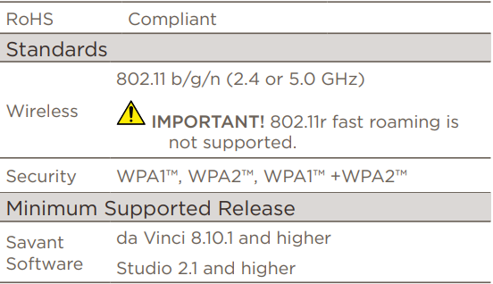
Front Panel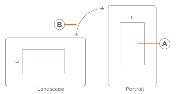
LCD Touchscreen – The display is a multi-colored touchscreen LCD that includes various screens for viewing and configuring the HVAC system.
- One touch and swipe operation.
- Swipe right for local forecast (when enabled).
Both landscape and portrait type installations are supported. During the power-up process, the thermostat will auto-detect its positioning and make the proper adjustments. Mount the backplate, as described below.
Portrait – Mount the backplate, so the terminal strip with the O, G, Y2, Y1, etc. are located towards the top. More information is available in the Install Thermostat Mounting Plate section.
Landscape – Mount the backplate, so the reference designators on the terminal strips can be read. If reference designators are upside down, rotate the thermostat 180°.
Getting Started
Savant recommends having the following tools available for installation:
- Pencil
- #2 Phillips screwdriver
- Small slotted screwdriver
- Drill with 5/32 inch drill bit
- Wire stripper
- Needle nose pliers
- Measuring Tape
CAUTION: When replacing an older thermostat that contains mercury in a sealed tube, do not discard it into the trash. Refer to thermostat-recycle.org or similar website for information on how to dispose of properly.
Remove Old Thermostat
- Scroll through and record the current settings and schedules from the old thermostat.
- Switch OFF power at either the breaker panel or the switch that controls the HVAC system.
- Open the old thermostat and take a photo of the existing thermostat and wiring. The photo should reveal wire colors and terminal designations.
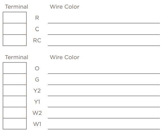
- Using the top chart to the right, add a check to record which power wires are installed in the old thermostat. In addition, record the wire colors. Not all fields from the chart may be populated.
- Remove each wire recorded and attach a label
that matches the terminal designation from the old thermostat. It’s important to label the wires according to the terminal designation and NOT the color of the wire. - Using the bottom chart to the right, add a check to record which HVAC signaling wires are installed in the old thermostat. In addition, record the wire colors.
- Remove each wire recorded above and add a wire label to each.
TIP: Wrap wires around a pencil or similar to prevent the wires from falling back into the wall - Remove old thermostat from wall.
Location and Mounting Overview
For new installations or when relocating the thermostat, follow the guidelines below:- Locate thermostat on an inside wall away from windows and doors to reduce the exposure to drafts or direct sunlight.
- Do not locate where air circulation is poor such as in a corner or behind a door.
- Install away from any heating conditions such as near a radiator register, vent, or fireplace.
- To adhere to ADA requirements, install thermostat 48 – 54 inches (1.22 – 1.37 meters) above the floor.
- Height requirements can be adjusted upward to 60 inches (1.5 meters) if ADA requirements are not mandatory.
- The thermostat does not need to be level to operate correctly. Leveling the thermostat is for aesthetics only.
- Thermostat can be oriented in either a portrait or landscape layout.
- Grasp the mounting plate half of thermostat in one hand, and the LCD screen half in the other.
TIP: Grasp the bottom of the thermostat, which is the end opposite the proximity sensor. - Pull the two halves apart and, at the same time, gently rock the front and back halves back and forth until they separate.
- Position the mounting plate onto the wall. Using a pencil, mark the two mounting holes onto the wall (See image).
- Use the bubble level in the center of the mounting plate to level when mounting using a portrait layout.
- When mounting using a landscape layout, remove the bubble level by pushing it out through the rear of the mounting plate and reinstall it into the bubble level slot on the right side of the center cutout. See the diagram to the right.
- With a #2 Phillips screwdriver, screw the wall anchor into the wall on each mark made. A 5/32 inch hole can be pre-drilled to make it easier when screwing the anchor to the wall. Wall anchors are not required with installs that have a sub wall to fasten to.
- Pull the existing wires through the center cutout in the mounting plate.
- Screw the mounting plate to the wall using the supplied screws.
HELPFUL: Additional information on the terminal designators and how to wire the thermostat into different types of HVAC systems is available in the Multistat Smart Thermostat Deployment Guide (009-1959-xx) available on the Savant Customer Community.
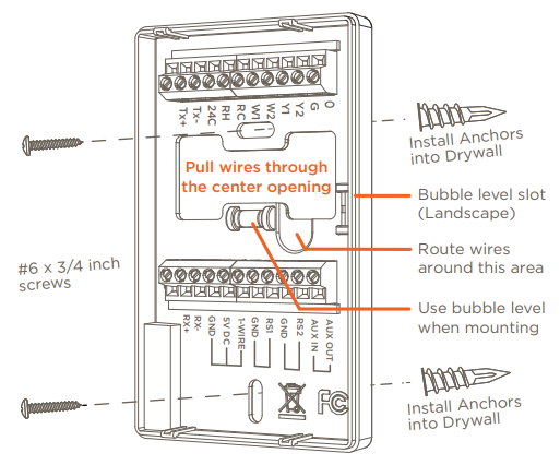
IMPORTANT: As indicated in the diagram above, route the thermostat wires around the wiring keepout. When the two halves of the thermostat are snapped together the component that rests in that indented area could be damaged.
Making Connections
When making connections, follow the guidelines set below to ensure a safe and secure connection.
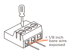
- With a small slotted screwdriver, turn the screws in the connector counterclockwise (CCW) until the silver crimps open enough to slide the wire(s) into square slots.
- Strip back insulation on each wire to 1/4 inch and insert the stripped wire into the proper connection.
- Turn screws clockwise (CW) until the crimps tighten around each wire. Gently tug on each wire to verify they are secure.
Connect Power – One Transformer used to power the HVAC system
The CLI-W210x does not run on batteries and requires a separate power source to operate. To power the thermostat, voltage must be applied between the RC and 24C terminals. When replacing an existing thermostat, if the power wires removed from the old thermostat were from the R and C terminals, use the diagram below to make the connections.
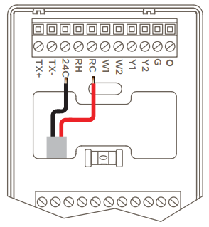
- RC – Connect the wire removed from the R terminal of the old thermostat to the RC terminal. On new installations, connect the wire from the 24V AC HVAC transformer to the RC terminal.
- 24C – Connect the wire removed from the C (common) terminal of the old thermostat to the 24C terminal. On new installations, connect the common wire from the 24V AC HVAC transformer to the 24C terminal.
Connect Power – Two Transformers used to power the HVAC system
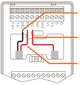
When an HVAC system uses separate power sources (two transformers) to run the heating and cooling HVAC systems, the HVAC system contains three power wires (R, C, and RC). Adjustments to accommodate the separate power sources are described below.
Jumper shunt JP1 on the thermostat’s PCB board connects the RH and RC terminals. Each thermostat shipped from the factory comes with this jumper shunt installed. With the shunt installed, one transformer, wired as described in the previous section, is needed. Remove the jumper shunt when the HVAC system contains separate transformers and make the connections described in the section below.
- RH – Supplies power to the relays connected to terminals W1, W2, and O.
- RC – Supplies power to the relays connected to terminals Y1, Y2, and G. RC terminal is also used to power the thermostat.
- 24C – Common terminal. The common wire from the HVAC system is required for thermostat to run.
HVAC Wiring
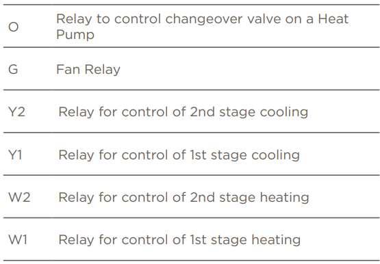
Use the table below when making connections between the thermostat and an HVAC system. The type of HVAC system installed determines which wires are connected and in some installations, the power wires are the only wires required.
HELPFUL
- Refer to the Making Connections section above to ensure a safe and secure connection is made.
- Additional information on the terminal desig-nators and how to wire the thermostat into different types of HVAC systems is available in the Multistat Smart Thermostat Deployment Guide located on the Savant Customer Community.
Remote Sensors
1-Wire Smart Sensor
An external temperature/humidity flush mount one wire compliant smart sensor can be purchased separately. This sensor can be used in place of the internal temperature/humidity sensor or used along with the internal sensor to calculate and display an average reading of the temperature and humidity in a room or space. Refer to the diagram below when making connections.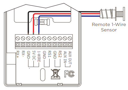
- See the Remote Temperature and Humidity Sensor (CLI-THFM1) QRG (009-1064-xx) for more information on this sensor
10K Thermistor
Included in the box is a 10KΩ thermistor type temperature sensor. The CLI-W210x includes two thermistor ports labeled RS1 and RS2 for this type of sensor. Like the smart sensor described above, this sensor can replace the onboard temperature sensor or can be used to calculate an average reading of the temperature in a room or space. The 10K sensors do NOT observe any polarity. Refer to the diagram below when making connections for 10K type sensors or thermistors.
Optional 10K Type Sensors
In addition to the 10KΩ thermistor type sensor included with the CLI-W210x, Savant offers a range of 10KΩ type sensors.
- SST-TEMP1-xx Flush Mount Remote Sensor (QRG: 009-0800-xx)
- SST-OTEMP-xx Outdoor Remote Sensor (QRG: 009-0989-xx)
- CLI-PLEN1R/C-xx Plenum Sensor (QRG: 009-1096-xx)
- CLI-SLAB1-xx SLAB Sensor (QRG: 009-1097-xx)
Connect to a Network
How to connect or on-board the thermostat to the local Wi-Fi® network from the on-screen menu is described below.
- Apply power to the thermostat. Verify the Select Network To Connect screen opens. All local networks will be listed.
- Select a network to add the thermostat to that network.
- Enter the password for the network using the on-screen keyboards.
- Select DONE when complete. The thermostat will verify the password credentials and connect to the network.
- The Configure HVAC System screen opens once the thermostat connects to the network. The option to configure basic HVAC system settings begins here. The Multistat Smart Thermostat Deployment Guide contains information on configuring a basic HVAC system using the ON DEVICE setup windows available from the thermostat’s LCD.
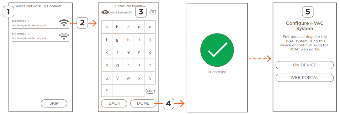
- Select the SKIP button to bypass the onboarding process and go directly to the Configure HVAC System screens. From here, the basic settings for the HVAC system settings can be established before onboarding the thermostat (Note: The onboarding process can be skipped if no Wi-Fi network is available).
- Select the eye icon
 to display the password characters.
- Select the keyboard character icon ( ABC ) to change the characters displayed in the Enter Password screen.
- Use one of the two methods described below to configure the HVAC system into the thermostat.
- DEVICE – Use the thermostat’s on-screen menus to configure the HVAC system settings.
- WEB PORTAL – Enter the IP Address of the thermostat, logon to the Web Portal, and use the menus in the web UI to configure the HVAC system settings.
Climate Modules
Savant offers a family of Climate Modules. These climate modules expand the capabilities of the thermostat. The modules available are as follows:
- CLI-1WIRE2 – Adds up to four 1-wire smart sensors to the system.
- CLI-10K4IN – Adds up to four 10KΩ type temperature sensors to the system.
- CLI-AUX3 – Adds up to three additional auxiliary relays to the system.
- CLI-REL1AUX1 – Adds a set of climate relays (W1, W2, Y1, Y2, G, O) and one auxiliary relay to the system.
- CLI-PTAC1K1 – Adds relays W1, W2, Y1, Y2, G, O for use with a PTAC and one 10KΩ temperature sensor to the system.
Connect Power To Climate Modules
Savant climate modules require 24V AC for power. The 24V AC used to power the thermostat can also power the climate modules. The diagram below displays the power connections between the thermostat and a climate module.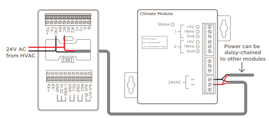
Connect RS-485 To Climate Modules
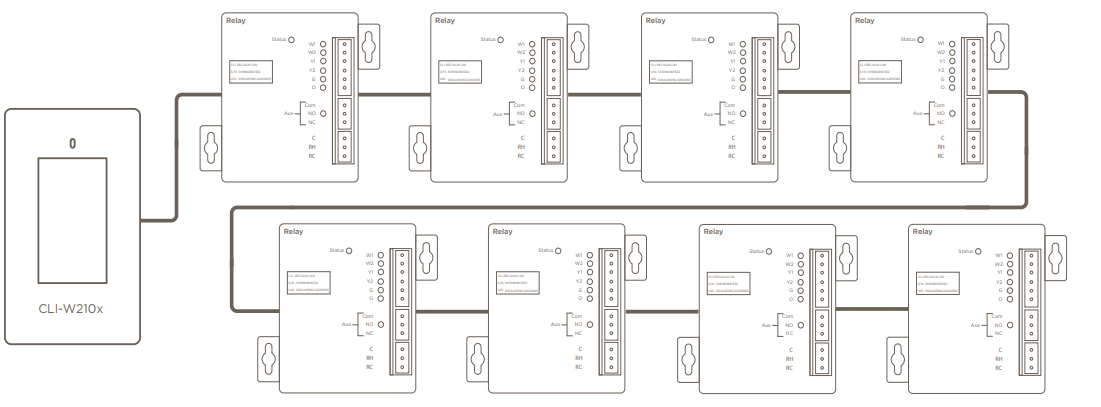
Savant climate modules communicate with the thermostat over RS-485. The diagram below shows the required connections.
HELPFUL
- RS-485 wiring must be connected using a daisy-chained fashion. Do not install the RS-485 wires in a home run type topology.
- A 120Ω terminating resistor installed between TX+ and TX- on the last climate module in the chain may be required on longer wire runs. Adding a terminating resistor will prevent stability issues that can occur with longer wire runs.
HELPFUL
For more information on each module, see the following guides on the Savant Customer Community.
- (009-1829-xx) – Sensor Module with Two 1-Wire Sensor Interfaces [CLI-WIRE2] – QRG
- (009-1798-xx) – Sensor Module with Four 10K Thermistor Inputs [CLI-10K4IN] – QRG
- (009-1799-xx) – Relay Module with Three Aux Relays [CLI-AUX3] – QRG
- (009-1806-xx) – Relay Module for PTAC with one 6-port Climate Relay and One 10K Thermistor [CLI-PTAC1K1] – QRG
- (009-1805-xx) – Relay Module with one 6-port Climate Relay and One Aux Relay [CLI-REL1AUX1] – QRG
- (009-1959-xx) – Multistat Smart Thermostat Deployment and User Guide
Example 1: Example 1 shows eight CLI-REL1AUX1 relay modules. Each module uses the HVAC signaling outputs to control a separate zone.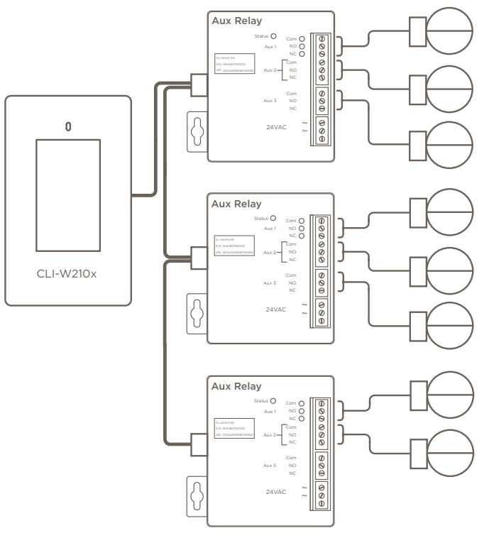
- Any combination of CLI-REL1AUX1 and CLI-PTAC1K1 modules that equal eight zones is acceptable.
- Any number of sensor type modules can be added once the eight zones are established. Modules such as the CLI-1WIRE2 and CLI-10K4IN) do not affect the maximum.
Example 2: The diagram below shows 3 Aux Relay modules with each relay output controlling a separate damper. Each damper is considered a different zone. Therefore, the maximum number of 8 zones is reached.
- Any combination of CLI-AUX3 and CLI-REL1AUX1 modules that equal 8 dampers/zones is acceptable.
- Once the 8 zones are established, any number of sensor modules (CLI-1WIRE2, CLI-10K4IN) can be added. Those modules do not affect the maximum.
- Use the diagram for reference only. Refer to the QRG’s for the CLI-REL1AUX1 or CLI-AUX3 module for information on wiring a vent damper.\
Frequently Asked Questions
- Does the CLI-W210x require batteries?
No, the CLI-W210x requires 24V AC that is typically available from a transformer or similar in the HVAC system. If the thermostat getting replaced does not include a common (C) wire, a separate wire must be run from the HVAC system to the Savant thermostat. - How does CLI-W210x get software updates?
The thermostat periodically receives Over The Air (OTA) updates automatically from the Savant Cloud. To obtain the update, the CLI-W210x must be connected to a local network that has WAN access, and be configured in a Savant system. - Will CLI-W210x still work if the Wi-Fi connection is lost?
Yes, most thermostat functions still work when not connected to Wi-Fi. However, features such as schedules and OTA updates that require a network connection will not. - My thermostat was received damaged. What should I do?
If the thermostat was purchased through a contractor or retailer, contact the contractor or retailer to return it. If thermostat was purchased from the Savant Store, contact Savant through the Savant Customer Community. - Are both Fahrenheit and Celsius supported?
Yes - Does the thermostat support humidity?
Yes, humidity can be monitored by one of the following:- An onboard combination humidity/temperature sensor.
- An optional remote 1-wire combination humidity/temperature smart sensor is available from the Savant Store (CLI-THFM1).
- Is the thermostat a single or dual setpoint thermostat?
Both. The thermostat can function as either a single or dual setpoint thermostat. To do this, select the correct profile from Blueprint and select the right mode (dual or single setpoint) from the thermostat’s on-screen menus. For additional information on the Blueprint configuration, see the Multistat Smart Thermostat Deployment Guide available on the Savant Community. - Does the thermostat support Scheduling?
Scheduling is set up only via the Savant Pro App Climate service. - Can I configure the thermostat to calculate an average humidity reading if I have both the onboard and remote smart sensor (CLI-THFM1) connected?
Yes, When configured through the web UI, the user decides which sensors to use and whether to take the average. - What are the maximum number of climate modules that can be connected to a CLI-W210?
There is no fixed maximum number of modules. Instead, the max quantity of modules is determined by the number of zones. Each thermostat supports a maximum of 8 zones. How a user gets to those eight zones can vary. See Example 1 and Example 2 below for reference.
Multistat Smart Thermostat Quick Start Guide | 009-1908-03 Copyright ©2020 Savant Systems, Inc | 200723
45 Perseverance Way, Hyannis MA 02601 Savant.com | 508.683.2500
Reference
Download Manual:
Savant CLI-W210 Smart Programming Thermostat Product Specification Guide
Other Manual:
Savant CLI-W210 Smart Programming Thermostat User Guide
Savant CLI-W210 Smart Programming Thermostat Product Specification Guide