
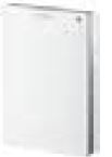
Siemens RDG405KN Room Thermostat

Room thermostats with KNX communications
- For VAV heating and cooling systems
- For room temperature and indoor air quality control
SPECIFICATION
- KNX bus communications (S- and LTE-Mode)
- Backlit display
- PI/P control
- Output for VAV box/air damper: DC 0…10 V/3-position/KNX LTE-Mode
- Output for heating/cooling coil: On/Off, PWM or 3-position/DC 0…10 V
- Output signal inversion as an option (DC 0…10 V à DC 10…0 V)
- 2 multifunctional inputs for keycard contact, external sensor, etc.
- 1 DC 0…10 V input for external sensor or feedback of air damper position
- Operating modes: Comfort, Economy, and Protection
- Control depending on the room or return air temperature
- Optimized operation of supply air fan: Input DC 0…10 V for feedback of air damper position
- Automatic or manual heating/cooling changeover
- The minimum and maximum limitation of room temperature setpoint
- The minimum and maximum limitation of airflow signal
- Adjustable commissioning and control parameters
- Commissioning with Synco ACS790, ETS, or via local HMI
- Integration into Synco; integration into Design via group addressing (ETS) or individual addressing
- Integration into the third-party system via group addressing (ETS)
- Indoor air quality (IAQ) control loop with external CO2 sensor (DC 0…10 V or KNX LTE- and S-Mode) (RDG405KN)
- Operating voltage AC 24 V
- Interworking with KNX CO2/temperature sensors (LTE- and S-Mode)
Use
The RDG40..KN room thermostats are designed for the following types of systems: VAV systems via On/Off or modulating control outputs or KNX LTE-Mode:
- Single-duct system
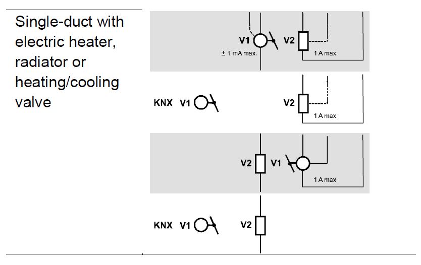
- A single-duct system with an electric heater
- Single-duct system and radiator/floor heating
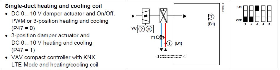
- A single-duct system with heating/cooling coil
The room thermostats are delivered with a fixed set of applications.
The required application is selected and activated during commissioning using one of the following tools:
- Synco ACS
- ETS
- Local DIP switch and HMI
Functions
- Room temperature control via built-in temperature sensor or external room temperature/return air temperature sensor
- Indoor air quality control via external CO2 sensor (DC 0…10 V, KNX LTE- or SMode) (RDG405KN)
- Changeover between heating and cooling mode (automatically via local sensor or bus, or manually)
- Selection of applications via DIP switches or commissioning tool (ACS790, ETS)
- Parameter download with commissioning tool (ACS, ETS)
- Selection of operating mode via the operating mode button on the thermostat
- Temporary Comfort mode extension
- Minimum and maximum limitation of room temperature setpoint
- The minimum and maximum limitation of airflow signal (selectable via ETS)
- External CO2 sensor, DC 0…10 V; 0…2000 ppm (RDG405KN)
- External CO2 sensor, KNX; 0…5000 ppm (RDG405KN)
- Button lock (automatic or manual)
- 2 multifunctional inputs, freely selectable for:
- Operating mode switchover contact (keycard, window contact, etc.) (RDG400KN)
- Window contact switches the operating mode to Protection (RDG405KN)
- The presence detector switches the operating mode to Comfort (RDG405KN)
- Changeover sensor for automatic heating/cooling mode
- External room temperature or return air temperature sensor
- Dewpoint sensor
- Electric heater enable
- Faults
- Monitor input for temperature sensor or switch status
- 1 input DC 0…10 V for external sensor and feedback of air damper position
- Optimization of pressure control using …
- feedback of air damper position and current airflow value via KNX bus,
- or feedback of air damper position via DC 0…10 V input
- Floor heating temperature limit
- Reloading factory settings for commissioning and control parameters
- KNX bus (terminals CE+ and CE-) for communication with Synco or KNX-compatible devices
- Display of outside temperature or time of day via KNX bus
- Display of current room temperature or setpoint in °C and/or °F
- Display of CO2 external sensor value in ppm or with symbols (+++; ++-; +–) (RDG405KN)
- Time scheduling and central control of setpoints via KNX bus
- RMB7../RMU7.. controller (signal exchange over KNX) using …
- the air demand signal of the thermostat to optimize the supply air temperature,
- the energy demand signals of the heating/cooling equipment to optimize the supply of energy,
- the feedback of the air damper position (DC 0…10 V or KNX) to optimize operation of the supply air fan
Applications
The thermostat supports the following applications, which can be configured using the DIP switches at the rear of the unit or a commissioning tool.
DIP switches 1…5 need to be set to OFF (remote configuration, factory setting) to select an application via the commissioning tool
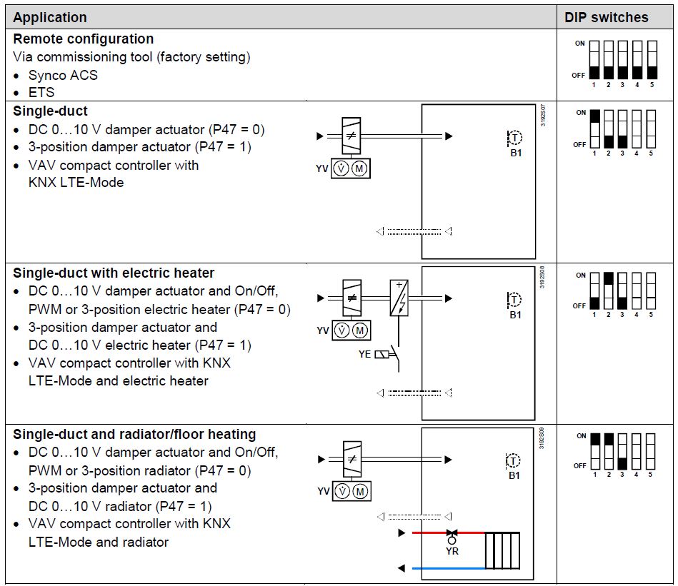
Note
- P47 is used to change air damper output from DC 0…10 V (factory setting) to 3-position
- P46 is used to change valve output from On/Off (factory setting) to PWM
- DIP switch 4 is used to change output of Y10 from DC 0…10 V to DC 10…0 V
- DIP switch 5 is used to change valve output from On/Off to 3-position
Type summary
| Product No. | Features | |||||||
| Operating voltage | Number of control outputs | Backlit LCD | ||||||
|
On/Off |
PWM |
3-pos. |
DC 0…10 V |
VAV
control via KNX LTE-Mode |
IAQ | |||
| RDG400KN | AC 24 V | 1 1) | 1 1) | 1 1) | 1 | ü | — | ü |
| RDG405KN | AC 24 V | 1 1) | 1 1) | 1 1) | 1 | ü | ü | ü |
Selectable: On/Off, PWM or 3-position (triac outputs)
Ordering
| Product No. | Stock No. | Description |
| RDG400KN | S55770-T165 | Room thermostat |
| RDG405KN | S55770-T346 | Room thermostat |
Order valve actuators separately.
Equipment combinations
Sensors
| Type of unit | Product No. | Data Sheet |
Cable temperature sensor  |
QAH11.1 | 1840 |
Room temperature sensor  |
QAA32 | 1747 |
Condensation monitor  |
QXA21.. |
A6V10741072 |
| AQR2576N.. | ||
Flush-mount KNX room sensor (base and front module)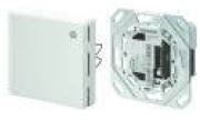 |
AQR2532NNW
AQR2530NNW AQR2532NNW |
1411 |
| AQR2535NNWQ |
|
Wall-mount KNX sensor |
QMX3.P30 QMX3.P70 |
1602 |
Valve actuators DC 0…10 V
Electric actuator, DC 0…10 V (for radiator valves)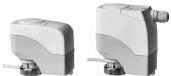 |
SSA61.. | 4893 |
Electric actuator, DC 0…10 V (for 2- and 3-port valves/V..P45)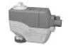 |
SSC61.. | 4895 |
Electric actuator, DC 0…10 V (for small valves 2.5 mm V..P47) |
SSP61.. | 4864 |
Electric actuator, DC 0…10 V (for small valves 5.5 mm V..P45)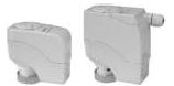 |
SSB61.. | 4891 |
Electric actuator, DC 0…10 V (for CombiValves VPI46) |
SSA61.. | 4893 |
Electromotoric actuator, DC 0…10 V (for valves 5.5 mm) |
SAS61.. | 4581 |
| Thermal actuator, DC 0…10 V
(for small valves and radiator valves) |
STP63 | 4884 |
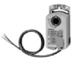
Damper actuators DC 0…10 V and 3-position, VAV compact controllers
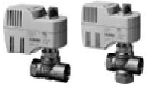
| Damper actuator DC 0…10 V, damper actuator 3-position |  |
GQD161.. GQD131.. | 4605 |
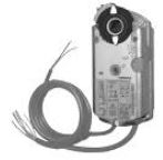
 |
GDB161.. GDB131.. |
4634 |
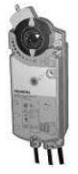
|
| GLB161..
GLB131.. |
|||
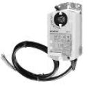
 |
GMA161.. GMA131.. | 4614 | |
| GEB161.. GEB131.. | 4621 | ||
 |
GCA161.. GCA131.. | 4613 | |
| GBB161.. GBB131.. |
4626 |
||
| GIB161.. GIB131.. | |||
|
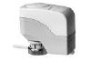
VAV compact controller |
GDB181.1E/3 |
3544 |
|
| GLB181.1E/3 | |||
VAV compact controllers KNX LTE-Mode
VAV compact controller for KNX LTE-Mode |
GDB181.1E/KN |
3547 |
| GLB181.1E/KN |
On/Off valve actuators AC 24 V
| Electromotoric On/Off valve and actuator
(only available in AP, UAE, SA and IN) |
 |
MVI../MXI.. |
4867 |
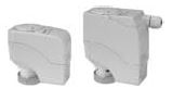
| Electromotoric On/Off actuator |  |
SFA71.. | 4863 |
On/Off/PWM valve actuators AC 24 V
| Thermal actuator (for radiator valves) |  |
STA73.. | 4884 |
| Thermal actuator
(for small valves 2.5 mm) |
 |
STP73.. | 4884 |
3-position valve actuators AC 24 V
| An electric actuator, 3-position (for radiator valves) | 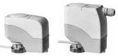 |
SSA81.. | 4893 |
| An electric actuator, 3-position
(for small valves 2.5 mm V..P47) |
 |
SSP81.. | 4864 |
| An electric actuator, 3-position
(for small valves 5.5 mm V..P45) |
 |
SSB81.. | 4891 |
| An electric actuator, 3-position (for CombiValves VPI46) |  |
SSA81.. | 4893 |
| Electromotor actuator, 3-position (for valves 5.5 mm) |  |
SAS81.. | 4581 |
With PWM control, it is not possible to ensure exact parallel running of more than one thermal actuator. If several actuators are controlled by the same room thermostat, preference should be given to motorized actuators with On/Off or 3-position control
Note
For more information about parallel operation and the maximum number of actuators that can be used, refer to the Data Sheets of the selected type of actuator and the following listing:
Maximum number of actuators in parallel operation in connection with RDG400KN and RDG405KN:
- 6 actuators S..81 (3-position)
- 4 actuators ST..73 (On/Off)
- 4 actuators SFA.., MVI.., MXI.. (On/Off)
- 10 damper actuators G..16.. DC
- 6 damper actuators G..13.. (3-position)
Accessories
| Description | Product No./stock No. | Data Sheet*) |
| KNX power supply unit 160 mA (Siemens BT LV) | 5WG1 125-1AB02 | — |
| KNX power supply unit 320 mA (Siemens BT LV) | 5WG1 125-1AB12 | — |
| KNX power supply unit 640 mA (Siemens BT LV) | 5WG1 125-1AB22 | — |
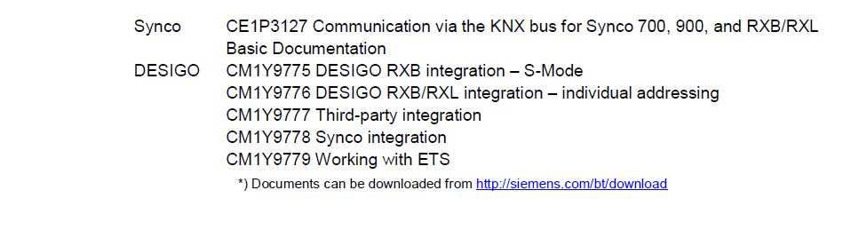
Documents can be downloaded from http://siemens.com/bt/download
Mechanical design
The room thermostat consists of 2 parts:
- Plastic housing with electronics, operating elements and room temp. sensor
- Mounting plate with screw terminals
The housing engages in the mounting plate and is secured with 2 screws.
Operation and settings
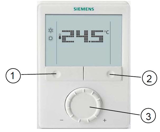
- Operating mode selector/Esc
- Protection and OK
- Rotary knob to adjust setpoints and parameters
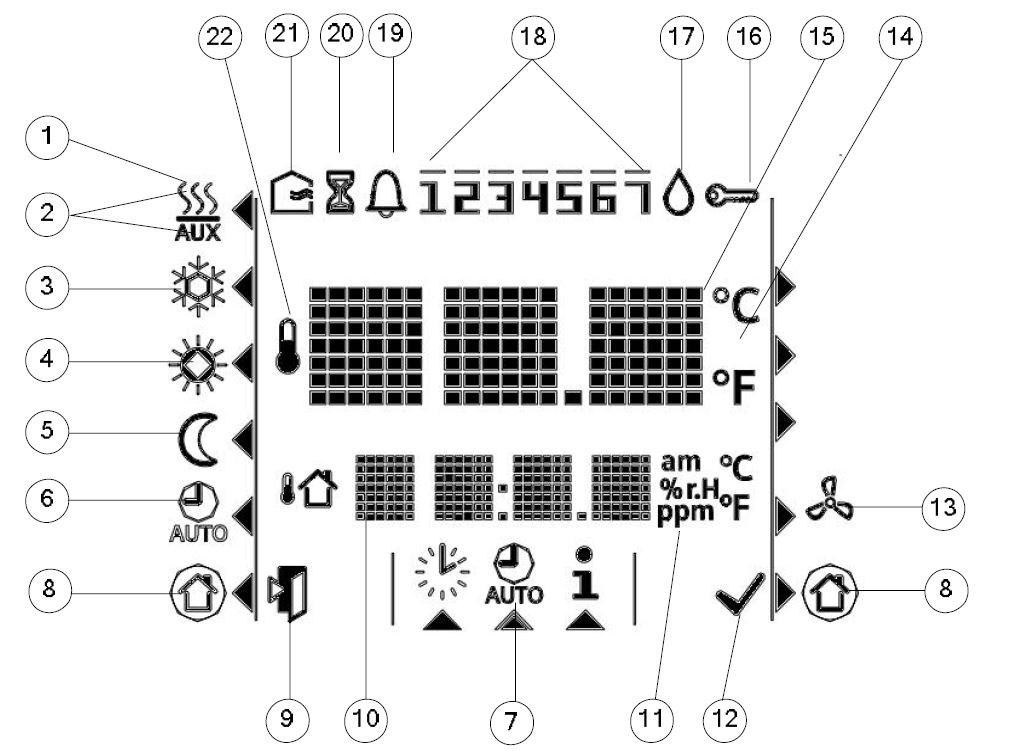
Display
- RDG400KN
- RDG405KN

Engineering notes
See “Reference documentation” below for information on how to engineer the KNX bus (topology, bus repeaters, etc.) and how to select and size connecting cables for power supply and field devices
Mounting and installation
Do not mount on a wall in niches or bookshelves, behind curtains, above or near heat sources, or exposed to direct solar radiation. Mount about 1.5 m above the floor.
Mounting
Mount the room thermostat on a clean, dry indoor place without direct air flow from a heating/cooling device, and not exposed to drip or splash water
Wiring
See Mounting Instructions M3192 (RDG400KN) or A6V10733804 (RDG405KN) enclosed with the thermostat.
- Comply with local regulations to wire, fuse and earth the thermostat
- Power supply line must have a circuit breaker with a rated current of no more than 10 A
- Isolate the cables of inputs X1-M, U1-G0 and D1-GND for 230 V if the conduit box carries AC 230 V mains voltage
- Inputs X1-M or D1-GND: Several switches (e.g. summer/winter switch) may be connected in parallel. Consider overall maximum contact sensing current for switch rating
- Isolate the cables of KNX communication input CE+/CE- for 230 V if conduit box carries AC 230 V mains voltage
- Disconnect the unit from power supply before removing it from its mounting plate
- If a KNX bus power supply is connected to the line with communicating thermostats and a Synco controller, the internal KNX power supply of the Synco controller must be switched off
Commissioning notes
Applications
The room thermostats are delivered with a fixed set of applications.
Select and activate the required application during commissioning using one of the following tools:
- Local DIP switch and HMI
- Synco ACS
- Version 5.11 or higher (for RDG400KN)
- Version 10.03 or higher (for RDG405KN)
- ETS
Set the DIP switches before snapping the unit to its mounting plate, if you want to select an application via DIP switches.
All DIP switches must be set to OFF (remote configuration), if you want to select an application via the commissioning tool.
After power is applied, the thermostat resets and all LCD segments flash, indicating that the reset was made correctly. After the reset, which takes about 3 seconds, the thermostat is ready for commissioning by qualified HVAC staff.
If all DIP switches are set to OFF, the display reads NO APPL to indicate that application commissioning via tool is required
Note
Each time the application is changed, the thermostat reloads the factory settings for all control parameters, except for KNX device and zone addresses!
Connect to
For commissioning, connect the Synco ACS or ETS tool to the KNX bus cable at any point: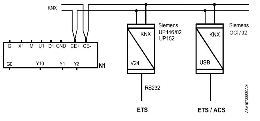
ACS and ETS3 require an interface:
- RS232 KNX interface (e.g. Siemens UP146/02, UP152)
- OCI702 USB-KNX interface
Note
An external KNX bus power supply is required if an RDG.. is connected directly to a tool (ACS or ETS) via KNX interface
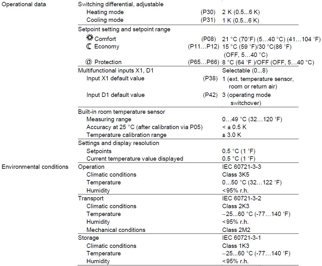
Control parameters
The thermostat’s control parameters can be changed to ensure optimum performance of the entire system (see Basic Documentation P3192).
The parameters can be adjusted using
- the local HMI
- Synco ACS
- ETS
Control sequence
The control sequence may need to be set via P01 depending on the application. The factory setting is “Cooling only
Calibrating the sensor
Recalibrate the temperature sensor if the room temperature displayed on the thermostat does not match the room temperature measured (after min. 1 hour of operation). To do this, change P05
Setpoint and setpoint range limitation
We recommend to review the setpoints and setpoint ranges (P08…P12) and to change them as needed to ensure maximum room comfort and to save energy
Programming mode
The programming mode helps identify the thermostat in the KNX network during commissioning.
- Press the left and right buttons simultaneously for 6 seconds to activate programming mode, which is indicated on the display with PrOg.
- Programming mode remains active until identification of the thermostat is complete
Assigning the KNX device address
- Assign the device address (P81) via HMI, ACS or ETS.
- To deactivate communication, set the device address to 255 (no exchange of process data)
Assigning the KNX group addresses
Use ETS to assign the KNX group addresses of the RDG communication objects.
KNX serial number
Each device has a unique KNX serial number inside the plastic housing. An additional sticker with the same KNX serial number is enclosed in the packaging box. This sticker is intended for installers for documentation purposes.
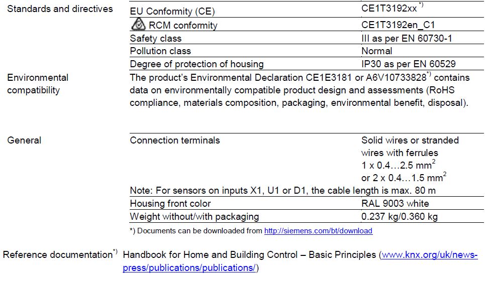
Disposal
The device is considered electrical and electronic equipment for disposal in terms of the applicable European Directive and may not be disposed of as domestic garbage.
- Dispose of the device through channels provided for this purpose.
- Comply with all local and currently applicable laws and regulations.
Technical data
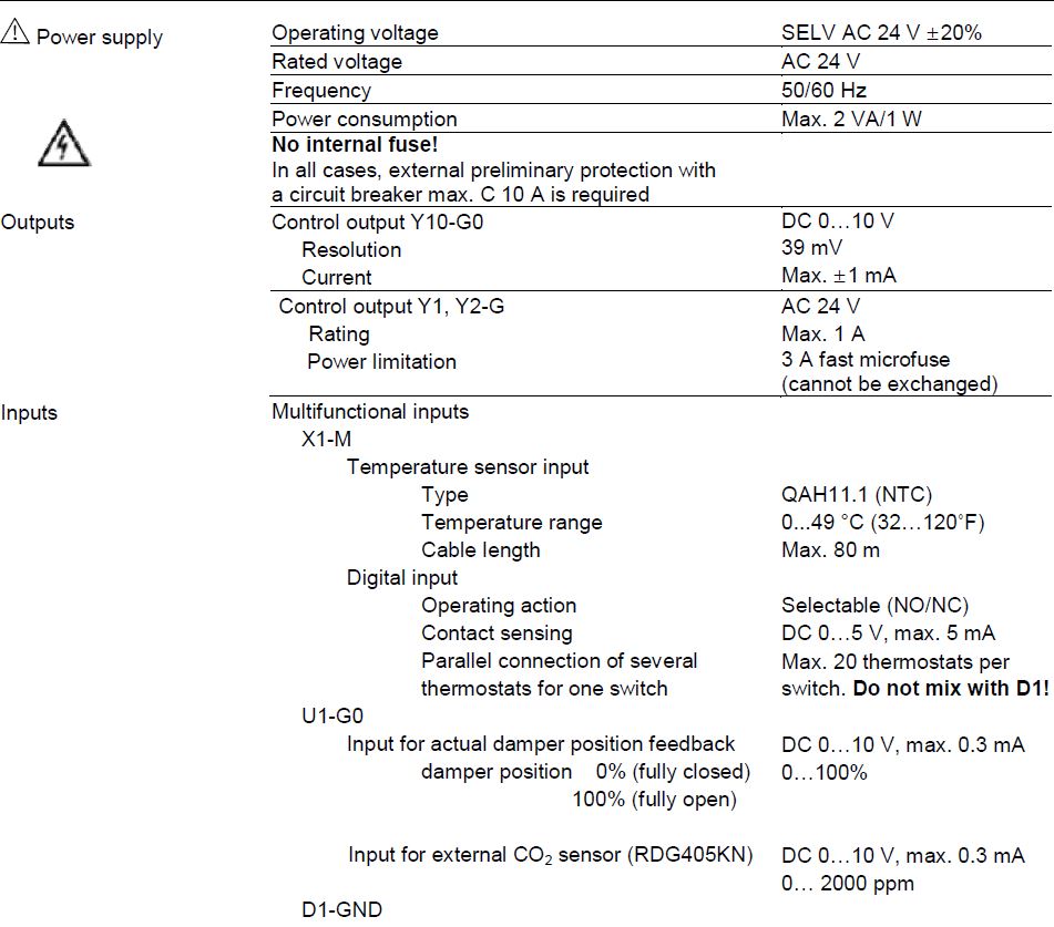
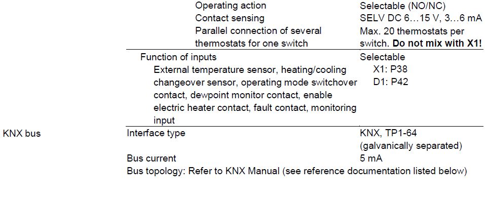
Connection terminals
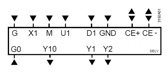
- G-G0 Operating voltage AC 24 V
- Y10-G0 Control output for DC 0…10 V actuator
- Y1-G, Y2-G Control outputs for On/Off, PWM or 3-position actuators
- X1-M
- Multifunctional input for temperature sensor (e.g. QAH11.1) or potential-free switch.
- Factory setting: External temperature sensor (function can be selected via P38)
- M Measuring neutral for sensors and switches
- U1-G0 DC 0…10 V input for current damper position DC 0…10 V input for CO2 sensor (0…2000 ppm) (RDG405KN) (Note: G0 is the measuring neutral for U1!)
- D1-GND Multifunctional input for the potential-free switch. Factory setting: Operating mode switchover contact (function can be selected via P42)
- CE+ KNX data +
- CE- KNX data –
Connection diagrams
Application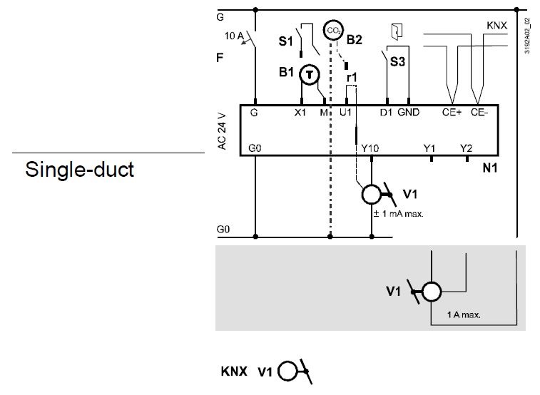
- N1 Room thermostat RDG400KN, RDG405KN
- V1 Damper actuator or VAV compact controller: DC 0…10 V or 3-position, VAV compact controller KNX
- V2 Electric heater, radiator or heating/cooling
- valve: DC 0…10 V, On/Off, PWM or 3-position
- S1 Switch (keycard, window contact, etc.)
- U1 DC 0…10 V input, feedback of current air damper position
- DC 0…10 V input for CO2 sensor (0…2000 ppm) (RDG405KN)
- S3 Switch at SELV input (keycard, window contact)
- B1 Temperature sensor (return air temperature, external room temperature, changeover sensor, etc.)
- B2 CO2 sensor (0…2000 ppm) (RDG405KN)
- CE+ KNX data +
- CE- KNX data –
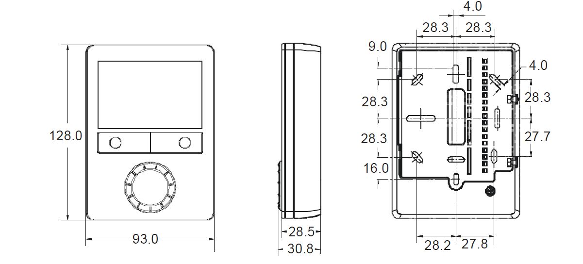
Dimensions
Dimensions in mm
© Siemens Switzerland Ltd, 2010 – 2019
Technical specifications and availability are subject to change without notice.
Issued by
Siemens Switzerland Ltd
Smart Infrastructure
Global Headquarters
Theilerstrasse 1a
CH-6300 Zug
Tel. +41 58 724 2424
www.siemens.com/buildingtechnologies
RDG40..KN Room thermostats with KNX communications
Siemens
Smart Infrastructure
REFERENCE:
DOWNLOAD MANUALS:
Siemens RDG405KN Room Thermostat Product Specifications Guide
OTHER MANUALS:
Siemens RDG405KN Room Thermostat Operating Instruction
Siemens RDG405KN Room Thermostat Product Specifications Guide
Leave a Reply