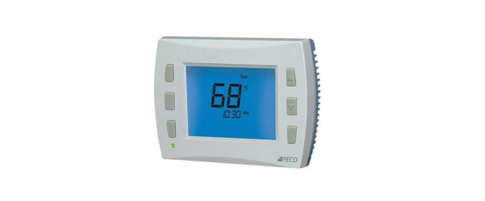
Peco T8168 Programable Thermostat
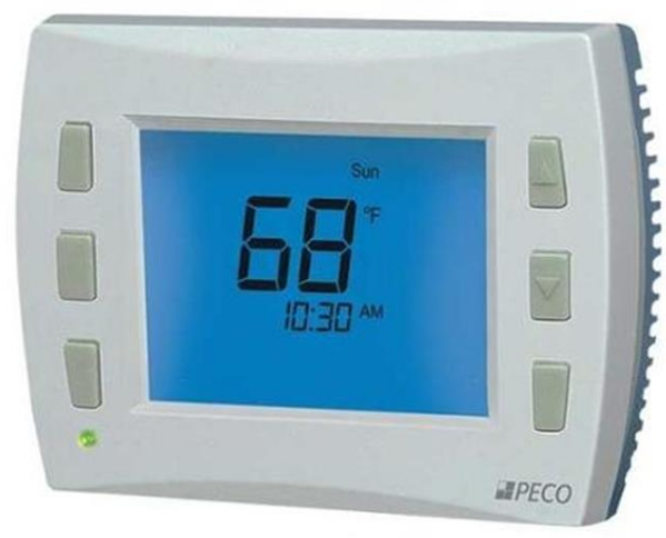
THE PECO COMMERCIAL T8168 THERMOSTAT
Thank you for choosing a PECO® Performance PRO™ thermostat. The T8168 thermostat is intended for commercial and residential environments. It supports both programmable and non-programmable operations. Key features include auto-changeover; optional remote sensor; three levels of keypad lockout with optional PIN access code; a heat/cool Demand Indicator; up to four scheduled events per day, a 365-day calendar, 20 holidays, holiday override, and temporary override.
Applications
The PECO® Performance PRO™ T8168 applications include fan coil, PTAC, and conventional system with a single, multi-speed, or 0-10 VDC Fan. System Mode Selections: Off-Heat-Cool-Auto
ON-OFF Heat/Cool Outputs: Up to 2 Heat, 2 Cool
Proportional Heat/Cool Outputs: Three Wire Floating or 0-10 VDC Control
Fan Control: Cycling (Auto) or Continuous (On); Up to 3 Speeds or Staged Permanent Memory: All device settings are stored in permanent memory. Optional Connections: Remote Sensor, Pipe Sensor, Fault Detection, and Setback
CAUTION!
- 24 VAC low-voltage thermostat. Do not install on voltages higher than 30 VAC.
- Use copper wire only
- Use care to avoid electrostatic discharge to the thermostat
RATINGS
- Outputs: Y1, Y2, W1, W2, G, G1 24 VAC (20-30 VAC); 50/60 Hz 10 VA
- Outputs: WD, GD, YD 0-10 VDC: Loads must be 1.2K ohms minimum 4-20 mA: Loads must be 600 ohms maximum
- This thermostat uses triacs switching for accuracy and quiet operation
Note: A load must be connected to outputs for testing
INSTALLATION INSTRUCTIONS
Select an appropriate thermostat location
Locate the thermostat about four feet (1.2m) above the floor on a wall with good ventilation, average temperature, and good response to temperature changes.
The T8168 may be mounted on a:
- Horizontal or vertical 2” X 4” device box
- Horizontal 4” X 4” device box
- Flat surface
- Do not locate the thermostat where it can be affected by:
- Direct sunlight
- Drafts or dead areas behind doors
- Radiating heat or cooling from appliances or equipment
- Concealed pipes or chimneys
- Outside walls or unheated/uncooled areas
- Required components (not included, unless otherwise specified):
- Screws and wall anchors (included)
- Screwdrivers: Phillips (for wallplate); small flathead (for terminal blocks)
- Drill with 3/16” drill bit (or 7/32” for plaster)
- Wire cutter and stripper
- Level
WARNING
- READ THESE INSTRUCTIONS CAREFULLY BEFORE ATTEMPTING TO INSTALL, OPERATE OR SERVICE THIS THERMOSTAT. Failure to observe safety information and comply with instructions could
result in PERSONAL INJURY, DEATH, AND/OR PROPERTY DAMAGE. - To avoid electrical shock or damage to equipment, disconnect the power before installing or servicing and use only wiring with insulation rated for full thermostat operating voltage.
- Use care to avoid electrostatic discharge.
- To avoid potential fire and/or explosion do not use in potentially flammable or explosive atmospheres.
- Retain these instructions for future reference.
This product, when installed, will be part of an engineered system whose specifications and performance characteristics are not designed or controlled by PECO®. Review applications and national and local codes to assure that the installation will be functional and safe.
TERMINAL BLOCK DESIGNATIONS
| Terminal | Description | Return To | |
| 24 VAC-1 | 24 VAC 1 (UNSWITCHED) | ||
| 24 VAC-2 | 24 VAC 2 | ||
| 24 VAC-2 | 24 VAC 2 | ||
| Y1 | COOL 1 | COOL Open (TWF) | 24 VAC 1 |
| W1 | HEAT 1 | HEAT Open (TWF) | 24 VAC 1 |
| Y2 | COOL 2 or FAN 3 (MED) | COOL Close (TWF) | 24 VAC 1 |
| W2 | HEAT 2 | HEAT Close (TWF) | 24 VAC 1 |
| G | FAN 1 (HI) | 24 VAC 1 | |
| G1 | FAN LO or DAMPER Configurable | 24 VAC 1 | |
| YD | 0-10VDC COOL (4-20mA) | 24 VAC 2 | |
| WD | 0-10VDC HEAT (4-20mA) | 24 VAC 2 | |
| GD | 0-10VDC FAN (4-20mA) | 24 VAC 2 | |
| S1 | REMOTE SENSOR, FAULT DETECTION | SC | |
| S2 | PIPE SENSOR | SC | |
| SC | DC/SENSOR COMMON | ||
| 4A | Not Available | ||
| 4B | Not Available | ||
| 4C | Not Available | ||
- WARNING: Disconnect power before beginning installation.
- CAUTION: Use copper wire only
- CAUTION: Do not connect unused wires together
TECHNICAL SPECIFICATIONS
- Temperature Control Range: 50° to 90° F (10° to 32° C)
- Differential: 1° F (0.5°C)
- Input Power: 24 VAC (20-30 VAC) 50/60 Hz (+/- 10%)
- Terminal Connections: 14-24 AWG stranded or solid wire
- Operating Temperature: 0° to 120°F (-18° to 49°C)
- Shipping/Storage Temperature: -20° to 130°F (-29° to 54°C)
- Operating Humidity: 5% to 95% RH, non-condensing
- Physical Dimensions: 4.3” H x 5.7” W x 1.3”D
- Proportional Output Band Width: 2°F (1°C)
- Proportional Stroke Time Default: 2 Minutes (Configurable)
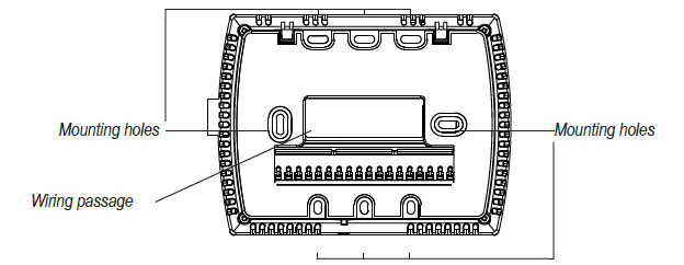
PART I: INSTALL WALL PLATE
- Position the wall plate on the wall with the directional arrow pointing up and terminal blocks facing outward.
- Pull equipment wires through the wall plate wiring passage.
- Use a level to determine the best horizontal wall plate mounting position.
- Mark the positions of screw holes (two) with a pencil and remove the wall plate.
- Drill holes at pencil-marked locations (3/16” for drywall, 7/32” for plaster).
- Insert the wall anchors in the holes, tapping them into place.
- Mount the wall plate onto the wall and insert screws through mounting holes. Assure that all loose wires come through the center opening of the wall plate.
Note: Do not over-tighten screws or use excessive force. This can cause the wall plate to warp and may cause intermittent connections between the base and the thermostat. - Cap off any unused wires and terminate properly according to the local building codes.
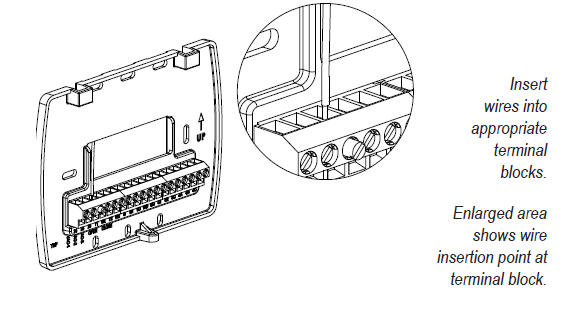
PART II: ATTACH WIRES TO THERMOSTAT WALL PLATE
- Select the terminal designations that correspond to the system type.
- Using a small flathead screwdriver, loosen the screws on the terminal blocks, Strip the insulation of each wire at a proper length (about 1/4” or 64 cm), and insert wires into the terminal blocks.
- Assure that no uninsulated wires are exposed: Cap off and place a wire nut on any unused wires. Assure that the attached wires fit into the cavity on the back side of the thermostat.
PART III: CONNECT POWER TO THE THERMOSTAT WALL PLATE
- The T8168 operates on 24VAC power.
- Connect the common side of the transformer to the “24 VAC-1” terminal.
- Connect the power side to the “24 VAC-2” terminal.
NOTE: Wait at least one hour for the displayed temperature to stabilize.
PART IV: MOUNT THE T8168 ONTO THE WALL PLATE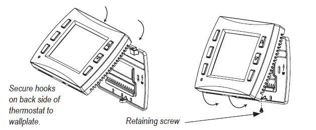
- Position the thermostat slightly above the mounted wall plate, then secure the hooks on the back side of the thermostat to the hinge pockets on the wall plate.
Note: The top back side of the thermostat should slip into the hinge pockets easily. Do not use excessive force. - Align the pins on the back side of the thermostat with the terminal blocks on the wall plate.
- Gently bring down the thermostat onto the wall plate so the pins on the back of the thermostat fit into the terminal blocks on the wall plate.
- Attach the retaining screw to the underside of the thermostat as shown.
PART V: SET CLOCK, MONTH, AND DAY
When power is first applied to the thermostat, it will activate the clock display. It is recommended that time and day are entered before performing the advanced configuration. Setting the clock can also be accessed by selecting MORE then CLOCK. Set the clock as follows:
- ▲/ ▼= Arrows set selection. Note: The flashing option is the default selection.
- NEXT = Advances to the next menu.
- Menu selections are: 12 to 24-hour format – Hour – Minutes – Year – Month – Day
- DONE = Press Done when the operation is complete.
NOTE: Display of Clock is not available when configured for non-programmable operation.
PART VI: VERIFY THERMOSTAT OPERATION WITH SYSTEM TESTS
System test verification is highly recommended to verify thermostat operation. For all system tests, press Next to continue to the following system test, or next available Service Menu. Press Done only if finished performing all system tests. Pressing Done exits the Service Menus and turns off all active outputs. See Service Menus: 600, 610, 620.
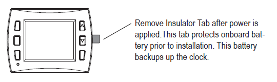
PART VII: REMOVE BATTERY INSULATOR TAB
| SM110 = | 1 | 2 | 3 | 4 | 5 | 6 | 7 | 8 | 9 | 10 | 11 | 12 | 13 | 14 | 15 | 16 | |
| 1 Heat
1 Cool 1 Fan |
2 Heat
1 Cool 1 Fan |
1 Heat
1 Cool 3 Fan |
2 Heat
1 Cool 3 Fan |
2 Heat
2 Cool 2 Fan |
Heat Only 1 Fan | Cool Only 1 Fan | Heat Only 2 Fan | Cool Only 2 Fan | Heat Only 3 Fan | Cool Only 3 Fan | Heat TWF 1 Cool
2 Fan |
TWF Heat 1 Cool
3 Fan |
TWF Cool 1 Heat
2 Fan |
TWF Heat TWF Cool 2 Fan | 0-10
VDC Only |
||
|
ON-OFF Outputs |
Y1 | Cool 1 | Cool 1 | Cool 1 | Cool 1 | Cool 1 | – | Cool 1 | – | Cool 1 | – | Cool 1 | Cool 1 | Cool 1 | Cool Open | Cool Open | – |
| W1 | Heat 1 | Heat 1 | Heat 1 | Heat 1 | Heat 1 | Heat 1 | – | Heat 1 | – | Heat 1 | – | Heat Open | Heat Open | Heat 1 | Heat Open | – | |
| Y2 | – | – | FAN MED | FAN MED | COOL 2 | – | Cool 2 | – | Cool 2 | FAN MED | FAN MED | Cool2 | FAN MED | Cool Close | Cool Close | – | |
| W2 | – | Heat 2 | – | Heat 2 | Heat 2 | Heat 2 | – | Heat 2 | – | Heat 2 | – | Heat Close | Heat Close | Heat 2 | Heat Close | – | |
| G | FAN | FAN | FAN HI | FAN HI | FAN HI | FAN | FAN | FAN HI | FAN HI | FAN HI | FAN HI | FAN HI | FAN HI | FAN HI | FAN HI | – | |
| G1 | Damper | Damper | FAN LO | FAN LO | FAN LO | Damper | Damper | FAN LO | FAN LO | FAN LO | FAN LO | FAN LO | FAN LO | FAN LO | FAN LO | Damper | |
| 0-10
VDC |
YD | Cool 1 | Cool 1 | Cool 1 | Cool 1 | Cool 1 | – | Cool 1 | – | Cool 1 | – | Cool 1 | Cool 1 | Cool 1 | Cool 1 | Cool 1 | Cool 1 |
| WD | Heat 1 | Heat 1 | Heat 1 | Heat 1 | Heat 1 | Heat 1 | – | Heat 1 | – | Heat 1 | – | Heat 1 | Heat 1 | Heat 1 | Heat 1 | Heat 1 | |
- When System Fan Type (SM112) is set to 1 or 2 (0-10 VDC operation), the GD output is the only fan output and G1 provides Damper operation.
- When Fan Coil 2-Pipe operation is selected the W1 and WD outputs will be disabled. See SM 171.
THERMOSTAT PROGRAMMING
This thermostat is easily changed from non-programmable to programmable operation in Service Menu 100. See the Operating Manual for detailed instructions on setting up schedules. In non-programmable mode, the thermostat controls to a single setpoint with the dead band used for auto changeover from Heat to Cool.
OUTPUT OPERATION
The T8168 uses System Types for control of 24 VAC ON-OFF fans and relays; three wire floating and proportional 0-10 VDC fans, valves and dampers.
- ON-OFF outputs have a 1°F Differential.
- Proportional outputs use a Proportional Integral Algorithm to modulate the position of the actuator over 2°F.
- Three Wire Floating outputs have an adjustable stroke time that is set in Service Menu 114. The default is 2 minutes. When using Three Wire Flotation (TWF) System Types wait 3 times the value set
for Valve Stroke Time, set in SM 114, for normal operation to begin.
FAN AND DAMPER OPERATION
The T8168 offers either ON-OFF or 0-10 VDC fan operation, as follows: ON/OFF FAN Operation (Service Menu 112 Selection 0) The thermostat will provide up to 3 fan speeds. In this operation, there is no
proportional fan output, and terminal GD is disabled. Selectable fan speeds are controlled by Service Menu 110. 0-10 VDC FAN HI-MED-LOW Operation (Service Menu 112 Selection 1)
User selection of 0-10 VDC (or 4-20mA) fan speed is as follows:
- HI – Set in SM 125 for heating and SM 126 for cooling.
- MED – Controls at the midpoint between the HI and LO settings.
- LO – Set in SM 127.
A delay of fan speed transition after adjustment can be set in SM 113. Proportional 0-10 VDC Operation (Service Menu 112 Selection 2) The 0-10 VDC fan will range between MAX and Min Voltages (SM 125,126,127) based on the PI algorithm, the active demand, and selected limits. The display of HI-MED-LO is suppressed. User selection is limited to FAN ON or FAN AUTO, depending on the configuration.
Damper Operation (Service Menu 111)
A damper output is available when terminal G1 is not being used as a fan speed. Cycled vs continuous operation is determined in SM 111. Staged Fan Operation (Service Menu 350) Available for multi-fan and 0-10 VDC fan operation. When active, the user does not have access to fan speed.
Programmable Fan Operation (Service Menu 500)
This feature changes the fan operation to ON (continuous) during scheduled Occupied events. TIP: Disable Fan ON selection in SM 350 to ensure cycled operation in unoccupied scheduled events. Intermittent Fan Operation (Service Menus 500, 501, 502) Provides minimum timed fan operation by cycling the fan on and off.
KEYPAD LOCKOUT
The keypad lockout function blocks access to features by hiding them from the user’s view/selectability. Service Menu 340 has 3 levels of lock-out. If a PIN is used to enter the Service Menu, all keypad lockouts will be disabled for a period of five minutes.
SETBACK
An occupancy sensor can be used between S1 & SC terminals to change the thermostat control points to Setback Low (SM 310) and Setback High (SM 320). A contact closure is used to signal a Setback requirement. In Setback the fan will cycle on at the lowest available speed. This feature is not available when using a remote sensor.
FAN COIL 2-PIPE/ 4-PIPE OPERATION
Service Menu 171 sets 2-pipe or 4-pipe fan coil operation.
| 2-Pipe Operation | Summer
(Cold Water or Open Input) |
Winter
(Hot Water or Closed Input) |
| Stage 1 Cool Y1 & YD | Cool | Heat |
| Stage 1 Heat W1 & WD | Disabled | Disabled |
2-pipe operation disables W1 and WD outputs. Y1 and YD are used for the first stage of cooling in summer and the first stage of heat in winter.
| 4-Pipe Operation | Summer
(Cold Water or Open Input) |
Winter
(Hot Water or Closed Input) |
| Stage 1 Cool Y1 & YD | Cool | Heat |
| Stage 1 Heat W1 & WD | Heat | Disabled |
The 4-pipe operation uses both first-stage Cool (Y1 & YD) and first-stage Heat (W1 & WD) when chilled water (Summer) is available. When hot water (Winter) is available W1 and WD outputs are disabled and Y1 and YD are used for first stage of heating. The second stages are available, depending on the system type.
PIPE SENSOR: SEASONAL CHANGEOVER
This feature is enabled when the 2-pipe or 4-pipe operation is selected in the Service Menu 171. With a pipe sensor connected to the T8168, the system will automatically change from Summer (cold water) to Winter (hot water) operation based on the water temperature in the main piping riser. This input is looking for a valid temperature reading when using a pipe sensor, or contact open/close if using an aqua-stat.
- Summer operation is enabled if the input is open or if the sensed temperature is below the threshold selection in SM 172.
- Winter operation is enabled if the input is closed or if the sensed temperature is above the threshold selection in SM 173.
If the water temperature sensed is between selections in SM 172 and SM 173 the water temperature is considered Ambiguous. The Y1 and YD outputs will be turned on for 3 minutes. After the 3-minute purge cycle, the thermostat checks again to see if the water temperature is Summer or Winter. If yes, the thermostat will transition to normal operation. If no, the operation is based on selection at Service Menu 174.
NOTE: If at any time the demand goes away, the thermostat will abort the purge cycle.
SYSTEM FLUSH FOR FAN COIL VALVES
Enable a periodic opening of valve(s) to flush valves and reduce sediment buildup using Service Menus 375, 376, and 377.
ACCESSORY SENSOR CONNECTIONS
S1 Input: connect optional remote sensing, occupancy detection, door open or fault notification.
- For Remote Probe use, including sensor averaging between the onboard sensor and the remote sensor, see SM 170.
- For occupancy, door open or fault notification see SM 175 S2 Input: uses a PECO pipe sensor or dry switch aqua-stat for use on fan coil seasonal changeover.
CONFIGURE SERVICE MENUS
The following Service Menus (SM) commonly require configuration. Please verify that these are set for your specific application. Additional configuration may be required.
- SM 100 = Programmable or Nonprogrammable
SM 110 = System Type - SM 112 = Fan Type
- SM 135 = W1 Heat Output NO or NC
- SM 170 = Remote Sensors
- SM 240 = Number of Programmable Events per Day
- SM 395 = Override Duration for Programmable Operation
- SM 340 = Keypad Lock Out
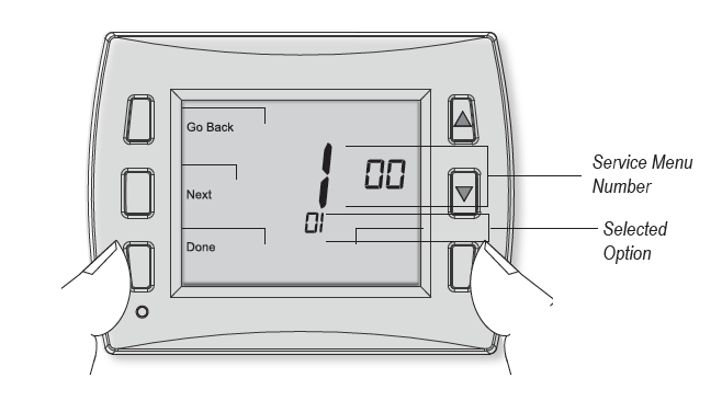
SERVICE MENU ACCESS
- Hold the lower right and lower left keys for five seconds.
- Press the Next or Go Back button to select a Service Menu.
- Press ▲/ ▼ to select the option.
- Press Done when complete
| Menu | Feature | Options | Description | |
| 100 | Schedule Format | 0 = Nonprogrammable (Default) | Selects the schedule format. In non-programmable mode all scheduling functions are removed from the display. | |
| 1 = Programmable | ||||
| 2 = 5-1-1 Schedule Mode | ||||
| 3 = 5-2 Schedule Mode | ||||
| 101 | Daylight Savings | 0 = Disabled (Default) | When enabled daylight savings time follows the US 2007 format. (Begins second Sunday of March at 2AM and ends on the first Sunday of November at 2AM. | |
| 1 = Enabled (2007 US Format) | ||||
| 110 | System Type | 1 | 1 Stage Heat /1 Stage Cool Fan: Single Speed | System Type Notes
• Fan can be changed from ON/OFF to 0-10 VDC Operation. • Stage 1 operation includes Y1/ W1 and 0-10 VDC outputs YD./ WD • System types may disable some service menu unavailablity • TWF = Three Wire Floating (valve)
Typical System Configuations: 2-Pipe Fan Coil with Electric Heat • Connect the Valve to Stage 1 Cool and the Heat Relay to Stage 1 Heat • SM110=01,02,03,04,05 or 14 • SM171=02 (4-Pipe Operation) • When using a pipe sensor, Operation of Cool Stage 1 will change. In winter, heating will be provided from the valve (Stage 1 Cool) and Electric Heat (W1) will be disabled. Error Detection/ Notification • Condensate overflow, door open or economizer can be set in Service Menu 175 • Connect external dry switch at S1 and SC. See wiring diagram. 0-10 VDC Fan Operation • Change SM112= 01 or 02 |
| 2 | 2 Stage Heat /1 Stage Cool Fan: Single Speed | |||
| 3 | 1 Stage Heat /1 Stage Cool Fan: 3-Speed | |||
| 4 | 2 Stage Heat /1 Stage Cool Fan: 3-Speed | |||
| 5 | 2 Stage Heat / 2 Stage Cool Fan: 2-Speed | |||
| 6 | Heat Only
Fan: Single Speed |
|||
| 7 | Cool Only
Fan: Single Speed |
|||
| 8 | Heat Only Fan: 2-Speed | |||
| 9 | Cool Only Fan: 2-Speed | |||
| 10 | Heat Only Fan: 3-Speed | |||
| 11 | Cool Only Fan: 3-Speed | |||
| 12 | Heat: TWF Cool: 2 Stage Cool Fan: 2-Speed | |||
| 13 | Heat: TWF Cool: 1 Stage Cool Fan: 3-Speed | |||
| 14 | Heat: 2 Stage Heat Cool: TWF Fan: 2-Speed | |||
| 15 | Heat: TWF Cool: TWF (Default) Fan: 2-Speed | |||
| 111 | Damper Configuration | 0 – Damper Continuous | Damper output is not available when being used as a fan speed.
0: G1 output runs continuously when thermostat is not in System OFF Mode. 1: G1 output cycles with a heat or cool demand. |
|
| 1 – Damper Cycled with Demand (Default) | ||||
| 112 | System Fan Type | 0 = On/Off Fan (Default) | 0: Uses available fan speeds per Service Menu 110
1: Uses GD output for 0-10 VDC fan. User selection of speed. HI Speed is set at SM 125-126,LO speed is set at SM 127, MED is set between HI-LO*. 2: Uses GD output for 0-10 VDC fan. Modulates between Min and Max selections in SM 125-127*. *Damper Output Available (G1) and runs per SM 111 |
| 1 = 0–10VDC FAN Hi-MED-LO Fan | |||
| 2 = Proportional 0-10VDC Fan | |||
| 113 | 0-10 VDC Fan Buffer | 0 to 3 Minutes, 30 sec Increments (Default 1) | Sets the time delay between fan speeds when SM 112=1 |
| 114 | Valve Stoke Time | 30 Sec To 5 Min (Default 120) | Set the amount of time for a TWF valve to go from fully closed to fully Open. |
| 120 | Fan Control (Heating) | 0 – OFF for Heating (Gas/Oil Heat) | 0: The thermostat will not activate the fan with a heating demand. 1: The thermostat will activate the fan with heat demand. |
| 1= Electric Furnace (DEFAULT) | |||
| 122 | YD Output Configuration | 0 = 4 – 20mA | Configures digital cooling output for 0-10VDC or 4-20mA DC |
| 1 = 0 – 10 Volts (DEFAULT) | |||
|
123 |
WD Output Configuration | 0 = 4 – 20mA | Configures digital heating output for 0-10VDC or 4-20mA DC |
| 1 = 0 – 10 Volts (DEFAULT) | |||
| 124 | GD Output Configuration | 0 = 4 – 20ma | Configures digital fan output for 0-10VDC or 4-20mA DC |
| 1 = 0 – 10 Volts (DEFAULT) | |||
| 125 | GD Max Voltage, Heating Demand | 6 – 10 VDC (Default: 8)
12 – 20 mA (Default: 20) |
Depending on SM 124 setting, sets Fan HI speed voltage or current (mA) at terminal GD with demand for Heat. |
| 126 | GD Max Voltage, Cooling Demand | 6 – 10 VDC (Default: 10)
12 – 20 mA (Default: 20) |
Depending on SM 124 setting, sets Fan HI speed voltage or current (mA) at terminal GD with demand for Cool. |
| 127 | GD Min Voltage | 0 – 6 VDC (Default: 2)
4 – 12 mA (Default: 4) |
Depending on SM 124 setting, sets Fan LO speed voltage or current (mA) at terminal GD with no demand. |
| 135 | W1 Output Configuration | 0 – NC: Normally Closed Operation (Default) | Reverses the ON/OFF operation for W1. NC operation powers on with a demand. NO opreation powers off with a demand and will be on with no demand unless main power is removed from the thermostat. |
| 1 – NO: Normally Open Operation | |||
| 170 | S1 Remote Sensor Input | 0= No Remote Sensors (Default) | 0: Remote temperature sensing is disabled.
1: The T8168 uses the remote sensor only for temperature sensing. 2: The T8168 averages the local and remote sensor for temperature sensing. When using a remote sensor an open or short will turn off outputs and display either 2Ero(open) or 2Erc (closed). Fault detection settings are not used. |
| 1= Remote Indoor Sensor Connected | |||
| 2 = Remote Sensor Connected And Sensor
Averaging |
|||
| 171 | S2 Pipe Sensor | 0 – Disabled (Default) | Enables fan coil pipe sensor operation. Connect a PECO pipe sensor or dry switch closure for change over from Summer (cold water) to Winter (hot water). 2-pipe operation uses the Cool 1 output for heating and cooling. Heat 1 is disabled. 4-pipe operation allows heat 1 in summer mode of operation.
Available when SM 110 = 1 through 5 or 14 through 16 |
| 1 – Two Pipe Operation | |||
| 2 – Four Pipe Operation (use for 2-pipe with electric heat relay) | |||
| 172 | Pipe Sensor Threshold for Cooling | 50F to 72F (Default 60F) | Changes to Cool when pipe temp is below threshold. Available when SM 171 = 1 or 2 |
| 173 | Pipe Sensor Threshold for Heating | 75F to 90F (Default 80F) | Changes to Heat when pipe temp is above threshold. Available when SM 171 = 1 or 2 |
| 174 | Pipe Sensor Purge | 0 = Time (Default) | TEMP: Purge continues until a non-ambiguous condition is sensed.
TIME: A 3-minute purge is started. Once complete and still ambiguous mode all thermostat outputs are disabled for 1 hour. Available when SM 171 = 1 or 2 |
| 1 = Temp | |||
| 175 | Fault Detection/ Setback
(requires SM170=0) No remote probe |
0 = Disabled (Default) | When enabled connect dry switch between S1 and SC. |
| 1 = Active On Open | Displays “Door” in clock location, turn outputs OFF, blink red LED | ||
| 2 = Active On Open | Displays “Fdd” in clock location, outputs function normally | ||
| 3 = Active On Close | Displays “Err” on clock location, turn outputs OFF blink red LED | ||
| 4 = Occupancy Sensor | Sets thermostat to setback with a closure at SC and S1 . | ||
| 240 | Number of Program Events | 2 or 4 Events (DEFAULT = 2) | When the T8168 is set up as programmable this sets the number of events per day. Events are OCC1, UNOCC1, OCC2, UNOCC2 |
| 250 | Clock Format | 12 or 24 Hrs (Default = 12) | This service menu sets the clock format. |
| 260 | F or C | 0- Celsius | Determines temperature displays in Fahrenheit or Celsius |
| 1- Fahrenheit (Default) | |||
| 270 | Fan Off Delay Heat | 0-99 Seconds (0-Default) | The amount of time (in seconds) the lowest available fan speed will run after the thermostat heating outputs are disabled |
| 280 | Fan Off Delay Cool | 0-99 Seconds (0-Default) | The amount of time (in seconds) the lowest available fan speed will run after the thermostat cooling outputs are disabled |
| 290 | Range Low | 50-90 F (50F- Default) | The lowest selectable temperature setpoint value |
| 300 | Range High | 50-90 F (90F Default) | The highest selectable temperature setpoint value |
| 310 | Setback Low | Off, 50-90 F (67F Default) | Accessed from Wi-Fi or by occupancy sensor detection. “Off” turns heating setpoint off. |
| 320 | Setback High | Off, 50-90 F (78F Default) | Accessed from Wi-Fi or by occupancy sensor detection. “Off” turns cooling setpoint off. |
| 330 | Zone Temp Offset | +/-9F (0F Default) | Zone Temperature offset adjusts the sensed Zone Temperature displayed, allowing calibra- tion in the field |
| 340 | Keypad Lockout | 0- No Key Pad Lockout (Default) | This function blocks access to certain features of the device. The Service Menu is still available if the key pad lockout is enabled.
If PIN is entered keypad lockout is overridden for 5 minutes. |
| 1- Disables Schedule and System Keys | |||
| 2 – Disables Schedule, System, And Fan Keys | |||
| 3 – Disables All Keys | |||
| 341 | Enable Pin Access | 0=Disable, 1= Enable (Default = 0) | Applies a 3-digit access code to enter service menu 342 |
| 342 | Set Pin | 000-999 (Default 000) | Selects pin access three-digit code. |
| 350 | Fan Mode | 1- On | ON: Fan is always on, regardless of demand.
User selections are: ON HI, ON MED, ON LO based on the number of fan speeds. |
| 2- Auto | Auto- Fan is only on with heating or cooling demand User selections are: AUTO HI, AUTO MED, AUTO LO based on the number of fan speeds. | ||
| 3- ON Or Auto (Default) | ON or Auto user can choose either selection. User selections are: AUTO HI, AUTO MED, AUTO LO, ON HI, ON MED, ON LO based on the number of fan speeds. | ||
| 4 – Staged Only | Fan speed selected from available speeds by thermostat per Fan Access section. User selections are: AUTO or ON. | ||
| 5- On Or Staged – Hotel Mode | ON- Fan is always on at user selected speed, regardless of demand
Auto Staged- Fan cycles off with demand. Fan speed is selected by thermostat from avail- able fan speeds. |
||
| 360 | System Mode | 0- Off, Auto | Sets the system modes the occupant is able to select
Hotel operation – For ease of use change available System modes to ON-AUTO SM360=02 |
| 1- OFF, Heat, Cool, Auto (Default) | |||
| 2- OFF, Heat, Cool | |||
| 3- Heat, Cool, Auto | |||
| 375 | System Flush Enable | 0 = No Flush (Default) | ▲! WARNING: Service Menu 375 may disable fan operation during valve flush. Enables the flush function for fan coil systems. This feature should be set to 0
(zero) unless outputs are connected to hydronic heating or cooling valves. Failure to follow this instruction can result in damage to equipment and/or property. |
| 1 = W1 Flush | |||
| 2 = Y1 Flush | |||
| 3 = W1 & Y1 Flush | |||
| 376 | Flush Duration | 1 To 3 Minutes (Default 1) | Defines how long to open the valve to perform the flush function |
| 377 | Flush Frequency | 0 = Every 24 Hrs (Default 0)
1 = Every 12 Hours 2 = Every 6 Hours |
Defines how often the flush is performed when output has remained inactive |
| 380 | Minimum Dead band Adjustment | 3F (Default) | A changeover dead band value prevents short cycling between heating and cooling modes. The value is adjustable to meet various HVAC system requirements. |
| 1-10F, 1.5-5C | |||
| 390 | Pre-Occupancy Purge | 0 Hours (Default) | Energizes the lowest fan available for selected number of hours (0-3) prior to events Occ 1 and Occ 2. This featrure applies to Programmable thermostat operation. |
| 0-3 Hours | |||
| 395 | Temporary
Occupied Duration Limit |
0-4 Hours (Default = 3) | This set the duration of a user override for programmable operation. 0: Will override the schedule until the next programmed event.
1,2,3,4: Sets the number of allowed hours of override after user adjustment. User can adjust override duration up to this limit of hours. |
| 480 | Minimum Off Time | 0-10 Minutes (Default 1 Minutes) | Sets the minimum off time for both the heat and cool output. |
| 500 | Programmable/ Intermittent Fan | 0- Disable (Default) | In programmable mode the fan will operate continuously during occupied periods or with demand during unoccupied/setback periods. In intermittent fan will operate based on the on and off times set in menus 501 and 502 whenever there is demand for fan. |
| 1 – Programmable Fan | |||
| 2 – Intermittent Fan | |||
| 3 – Intermittent Fan During Occupied Periods Only | |||
| 501 | Intermittent Fan On Time | 5 Minutes (Default) | Defines the duration in which fan low will be on. Fan On will be activated after Fan Off time has passed. |
| 1-60 Minutes | |||
| 502 | Intermittent Fan Off Time | 25 Minutes (Default) | Defines the duration in which fan low will be off. Fan Off will be activated after Fan On time has passed. A selection of 0 will result in continuous Fan. |
| 0-60 Minutes |
| 520 | Default Display Icons | 0- Time, Temp, SP (Default) | Icons that will be displayed in the default state.
NOTE: Setpoint will not be displayed if T8168 System Mode is OFF. |
| 1- Time, Temp | |||
| 2- Time | |||
| 3- Temp | |||
| 4- None | |||
| 5 – Set Point Only | |||
| 530 | Revision | Displays Current Revision Information | |
| 540 | Factory Default Reset | 0- Disable (Default) | When enable is selected he device will return to factory default settings. |
| 1- Enable | |||
| 600 | Cooling System Output Test | 0- Disable (Default) | Cool Operation is enabled and the associated output based on Service Menu 110. The output is activated for 10 minutes. The ON/OFF or 0-10 VDC Fan output will automatically turn on. |
| 1- Stage 1 Cooling/Y1 (TWF) | |||
| 2 – Stage 2 Cooling/Y2 (TWF) | |||
| 610 | Heating System Output Test | 0- Disable (Default) | Heat Operation is enabled and the associated output based on Service Menu 110. The output is activated for 10 minutes. The ON/OFF or 0-10 VDC Fan output will automatically turn on. |
| 1- Stage 1 Heating/W1 (TWF) | |||
| 2 – Stage 2 Heating/W2 (TWF) | |||
| 620 | Fan System Output Test | 0- Disable (Default) | If enabled is selected it will activate Based On Service Menu 110. The output will be enabled for 10 minutes. If a different menu is selected the output will be disabled. Wheth- er the fan output is a triac or a 0-10VDC/4-20mA is determined by Service Menu 112 |
| 1- Enable G Fan Output/GD Low | |||
| 2 – Enable Y2 Fan Output/GD Med Cool | |||
| 3 – Enable G1 Fan Output/GD Hi Cool | |||
| 4 – Enable GD Med Heat | |||
| 5 – Enable GD High Heat |
TROUBLESHOOTING & FREQUENTLY ASKED QUESTIONS
In case of difficulty, try one of the following suggestions below.
| Symptom | Potential Cause(s) | Solution |
| If display screen is blank | • Thermostat is not being powered | • Check to assure proper wiring of power to (24 VAC-1) and (24 VAC-2) .
• Check power to verify that there is 24 VAC available. |
| • Default Display is set to “4” (None) | • Check Service Menu 520. | |
| If keys do not allow manual entry | • Keypad Lockout may be enabled | • Access Service Menu 340. Within this menu, select option “0” to assure there is no keypad lockout (so manual entry is enabled). |
| Service Menu does not display | • PIN access is enabled
• Buttons were not pressed simultaneously |
• Access requires the three digit code set by the installer.
• Wait for unit to return to default display and retry. |
| Err In Clock Dispay | • Indicates a service fault input | • Indicates service is required. |
| Door in Clock Display | • Door or window is open | • Close door and /or window to clear fault. |
| Fdd in Clock Display | • Indicate an economizer or other system fault | • Indicates service is required. |
| If no heating or cooling is running, but there is a call for heat or cool (Heat/Cool appears on display) in Auto mode | • Heating or cooling equipment is not operating
• Minimum off time has not been met |
• Check Service Menu 110 to assure that the correct option is selected to match the system type.
• Check wiring, using output tests to verify (see Service Menus 600, 610, 620). |
| If heating or cooling system doesn’t respond | • System type selection is incorrect | • Check Service Menus 110 and 120 to assure that the correct option is selected to match the system type. |
| If heating and cooling equipment are running at the same time | • System type selection is incorrect | • Check Service Menu 110 to assure that the correct option to match the system type is selected. |
| • Verify wiring connections | • Separate the heating and cooling wires, using output tests to verify (see Service Menus 600, 610, 620). | |
| If Demand Indicator light is red | • Heating is occurring | • No action is required. |
| If Demand Indicator light is green | • Cooling system is running | • No action is required. |
| Fan outputs turned off after 3-minutes | • Pipe sensor is connected and water temperarture between hot water and cold water set points | • Building Boiler or Chillers may be turned off.
• See Service Menus 171, 172, 173 & 174 |
| Menu Item Not available | • Some service menus are disabled when not in use or feature is not available. | • Verify system type selection and feature selection is correct. |
| Red LED is Flashing and code is in clock location | • Fault is present on SC and S1 input | • Check SM175 for code
• If using a remote sensor, verify probe wiring. |
Wiring Diagram: ON-OFF Operation Wiring Diagram: Three-Wire Floating Operation

COPYRIGHT 2020 PECO, INC. ALL RIGHTS RESERVED P/N 73676 3220-2372 REV 04
REFERENCE:
DOWNLOAD MANUALS:
Peco T8168 Programable Thermostat Installation Guide
OTHER MANUALS:
Peco T8168 Programable Thermostat Product Specifications Guide
![]()
Leave a Reply