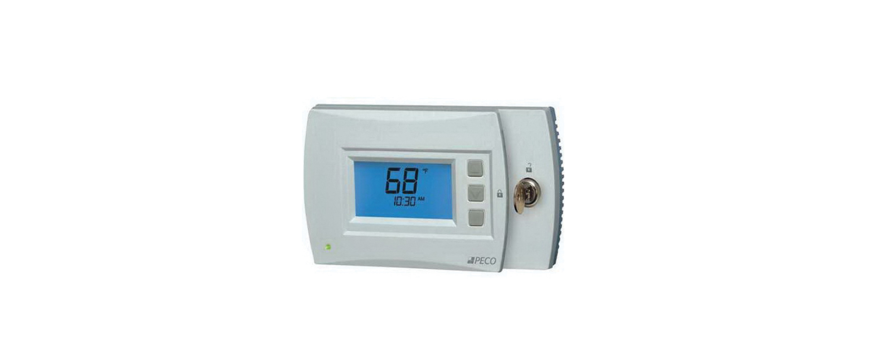
Peco T4900 Programmable Thermostat
The Peco PerFormance Pro t4900 school serIes thermostat
Thank you for choosing the PECO® Performance PRO™ T4900 School Series™ thermostat. The T4900 provides comfort conditioning for educational environments, reducing energy consumption and the bottom line. One-touch simplicity means users simply push the “Teacher” key to apply an energy-efficient School Schedule. The T4900 supports up to 3-HEAT/ 2-COOL configurations in conventional and heat pump applications. Users can choose between two modes in which to operate the T4900: as a standard Performance PRO or as a School Series. The Performance PRO T4900 School Series is comprised of the T4932SCH-001 programmable and the T4932SCH-002 programmable thermostat with humidification/dehumidification control. T4900 School Series standard features include 4 square inches of blue backlit display; Secure Digital (SD) card interface; locking cover; auto-changeover; School Schedule; inputs for occupancy/ remote sensors; three levels of keypad lockout and PIN access; furnace and UV filter reminders; Heat/Cool Demand Indicator; a 365-day calendar, 20 holidays; Power Harvesting (a.k.a. “power stealing”); and humidity control (T4932SCH-002 only). The T4900 Series can be powered by 24 VAC or batteries or both (recommended). The T4900 Series can control up to 7 outputs and monitor three external sensors (including a CO2 sensor). The T4900 Series mounts on any PECO Performance PRO Series common wallplate.
Applications anD FeatUres
The PECO Performance PRO thermostat is intended for use in conventional and heat pump applications.
- System mode selections: Off-Heat-Cool-Auto-Emergency
- Stages: 1 Heat/1 Cool, 2 Heat/1 Cool, 1 Heat/2 Cool; 2 Heat/ 2 Cool; 3 Heat/ /2 Cool
- Fan control: Cycling (Auto) or Continuous (On); 1 Speed
- Permanent memory: All device settings are stored in permanent memory.
- Connections for Remote Sensors (indoor/ outdoor/ occupancy/ CO2)
- SD card interface (card not included)
Caution!
- 24 vac low-voltage thermostat. Do not install on voltages higher than 30 vacs.
- Use copper wire only; insulate or cap off (with wire nuts) all unused leads.
- Use care to avoid electrostatic discharge to the thermostat.
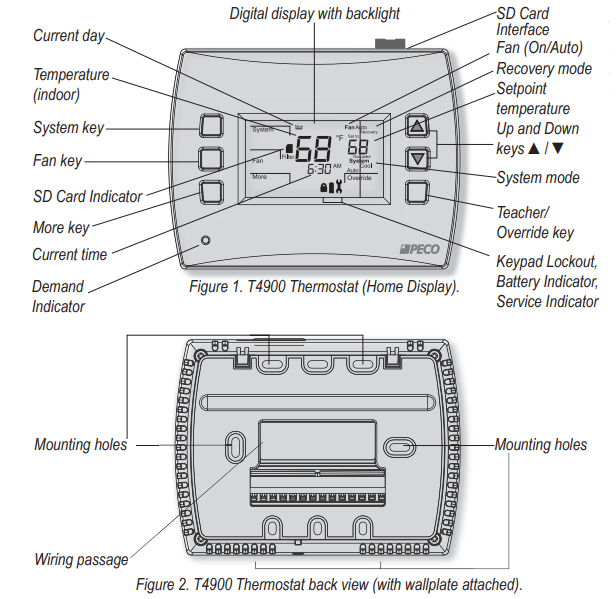
Front Panel reFerence: t4900 controls & DIsPlaY
Warning
- READ THESE INSTRUCTIONS CAREFULLY BEFORE ATTEMPTING TO INSTALL, OPERATE, OR SERVICE THIS THERMOSTAT.
- Failure to observe safety information and comply with instructions could result in PERSONAL INJURY, DEATH, AND/OR PROPERTY DAMAGE.
- To avoid electrical shock or damage to equipment, disconnect power before installing or servicing and use only wiring with insulation rated for full thermostat operating voltage.
- To avoid potential fire and/or explosion do not use it in potentially flammable or explosive atmospheres.
- Retain these instructions for future reference.
- This product, when installed, will be part of an engineered system whose specifications and performance characteristics are not designed or controlled by PECO. Review applications and national and local codes to assure that the installation will be functional and safe.
Product Specifications
Temperature Control
- Range: 50° to 90° F (10° to 32° C)
- Differential: 1° F (0.5°C)
- Input Power: 24 VAC (20-30 VAC) 50/60 Hz (+/- 10%) or AA alkaline batteries
- (both recommended); 5mm terminals accept 14-24 AWG stranded or solid wire.
- Operating Temperature: 0° to 120°F (-17° to 48°C)
- Shipping Temperature: -20° to 130°F (-28° to 54°C)
- Operating Humidity: 5% to 95% RH, non-condensing
- Physical Dimensions: T4900 Thermostat: 4.3” H x 5.7” W x 1.3”D
- with 2.7” x 1.5” / 4.05 square inch liquid crystal display (LCD)
- Output Ratings
- Voltage (50/60 Hz): 20-30 VAC
- Current: 0.02-1.0 A per terminal; W1 (B/O), W2 (AUX), G, A, E, Y1, Y2.
- Note: Collectively, the total current draw must not exceed 2.5 A.
Installation Instructions
Select an appropriate thermostat location
Locate the thermostat about five feet (1.5 m) above the floor on a wall in an area with good ventilation and an average temperature, where it will be responsive to changes in the room temperature.
The Performance PRO T4900 School Series may be mounted on a:
- Horizontal or vertical 2” X 4” device box
- Horizontal 4” X 4” device box
- Flat surface
- locate the thermostat where it can be affected by:
- Direct sunlight
- Drafts or dead areas behind doors
- Radiant heat from appliances
- Concealed pipes or chimneys
- Outside walls or unheated/uncooled areas
Required components (not included, unless otherwise specified):
- Two new AA batteries (included)
- Screws and wall anchors (included)
- Screwdrivers: Phillips (for wallplate); small flathead (for terminal blocks)
- Drill with 3/16” drill bit (or 7/32” for plaster)
- Wirecutter and stripper
- Level
- Performance PRO School Series T4900 Thermostat (included)
- Performance PRO School Series T4900 Thermostat Operating Manual (included)
Note: Secure Digital (SD) card interface (card not included) provides for quick transfer of customized settings to or from the thermostat. For instructions, see “load SD card settings” in the operating manual. For more information on Peco’s configurator, visit: www.pecomanufacturing.com/controls/
Part I: Install the wallplate
- Position the wallplate on the wall with the directional arrow pointing up (see Fig. 3) and terminal blocks facing outward
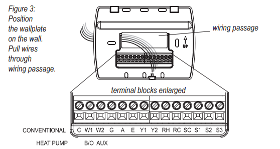
- Pull equipment wires through the wallplate wiring passage (see Fig. 3).
- Use a level to determine the best horizontal wallplate mounting position.
- Mark the positions of screw holes (two at minimum) with a pencil and remove the wall plate.
- Drill holes at pencil-marked locations (3/16” for drywall, 7/32” for plaster).
- Insert the wall anchors in the holes, tapping them into place.
- Mount the wallplate onto the wall and insert screws through mounting holes. Assure that all loose wires come through the center opening of the wallplate (see Fig. 3).
- Cap off any unused wires and terminate properly according to local building codes
Part II: Attach wires to Thermostat Wallplate
- Select the terminal designations that correspond to the system type (see Table 1).
- WARN ING: Disconnect power before beginning installation.
- CAUTION: Use copper wire only. Insulate or wire-nut all unused leads.
- Use care to avoid electrostatic discharge to the thermostat
table 1. Terminal design nations & system types
| Conventional Terminal Letters | Heat Pump Terminal Letters | ||
| c | Unswitched side, 24 VAC | c | Unswitched side, 24 VAC |
| w1 | Stage 1 Heat | B/o | Reversing Valve |
| w2 | Stage 2 Heat | aUX | Auxiliary (Stage 3 Heat) |
| G | Fan | G | Fan |
| a | Economizer/Damper/
Humidity |
a | Economizer/Damper/
Humidity |
| e | Stage 3 Heat | e | Emergency Heat |
| Y1 | Stage 1 Cool | Y1 | Compressor Stage 1, Heat /Cool 1 |
| Y2 | Stage 2 Cool (or Dehumidify) | Y2 | Compressor Stage 2, Heat /Cool 2
(or Dehumidify) |
| RH | Power for heating,
switched side, 24 VAC |
RH | Power for heating,
switched side, 24 VAC |
| RC | Power for cooling,
switched side, 24 VAC |
RC | Power for cooling,
switched side, 24 VAC |
| sc | Sensor Common | sc | Sensor Common |
| s1 | Indoor/ Outdoor
Remote Sensor |
s1 | Indoor/ Outdoor
Remote Sensor |
| s2 | Occupancy Sensor/
Setback Input |
s2 | Occupancy Sensor/
Setback Input |
| s3 | CO² Sensor/
Outdoor Remote Sensor |
s3 | CO² Sensor /Outdoor Remote Sensor
with Heat Pump Compressor Lockout* |
| System Type 1: 1H/1C Conventional | |
| TERM | Function |
| C | Common |
| W1 | Heat |
| W2 | |
| G | Fan |
| A | Economizer/Damper |
| E | |
| Y1 | Cool |
| Y2 | |
| RH | Power for Heating |
| RC | Power for Cooling |
| System Type 2: 1H/1C Heat Pump | |
| TERM | Function |
| C | Common |
| B/O | Reversing Valve |
| AUX | |
| G | Fan |
| A | Economizer/Damper |
| E | |
| Y1 | Compressor |
| Y2 | |
| RH | Power for Heating |
| RC | Power for Cooling |
| System Type 3: Heat only (without fan) | |
| TERM | Function |
| C | Common |
| W1 | Heat |
| W2 | |
| G | |
| A | Economizer/Damper |
| E | |
| Y1 | |
| Y2 | |
| RH | Power for Heating |
| RC | |
| System Type 5: Cool only | |
| TERM | Function |
| C | Common |
| W1 | |
| W2 | |
| G | Fan |
| A | Economizer/Damper |
| E | |
| Y1 | Cool |
| Y2 | |
| RH | Power for Heating |
| RC | Power for Cooling |
| System Type 6: 2H/1C Heat Pump (Aux.) | |
| TERM | Function |
| C | Common |
| B/O | Reversing Valve |
| AUX | Auxiliary Heat |
| G | Fan |
| A | Economizer/Damper |
| E | Emergency Heat |
| Y1 | Compressor |
| Y2 | |
| RH | Power for Heating |
| RC | Power for Cooling |
| System Type 6: 2H/1C Heat Pump (Aux.) | |
| TERM | Function |
| C | Common |
| B/O | Reversing Valve |
| AUX | Auxiliary Heat |
| G | Fan |
| A | Economizer/Damper |
| E | Emergency Heat |
| Y1 | Compressor |
| Y2 | |
| RH | Power for Heating |
| RC | Power for Cooling |
| System Type 7: 2H/2C Conventional | |
| TERM | Function |
| C | Common |
| W1 | Heat 1 |
| W2 | Heat 2 |
| G | Fan |
| A | Economizer/Damper |
| E | |
| Y1 | Cool 1 |
| Y2 | Cool 2 |
| RH | Power for Heating |
| RC | Power for Cooling |
| System Type 8: 2H/1C Conventional | |
| TERM | Function |
| C | Common |
| W1 | Heat 1 |
| W2 | Heat 2 |
| G | Fan |
| A | Economizer/Damper |
| E | |
| Y1 | Cool |
| Y2 | |
| RH | Power for Heating |
| RC | Power for Cooling |
| System Type 9: 1H/2C Conventional | |
| TERM | Function |
| C | Common |
| W1 | Heat |
| W2 | |
| G | Fan |
| A | Economizer/Damper |
| E | |
| Y1 | Cool 1 |
| Y2 | Cool 2 |
| RH | Power for Heating |
| RC | Power for Cooling |
| System Type 10: 2H/2C Heat Pump | |
| TERM | Function |
| C | Common |
| B/O | Reversing Valve |
| AUX | |
| G | Fan |
| A | Economizer/Damper |
| E | |
| Y1 | Compressor 1 |
| Y2 | Compressor 2 |
| RH | Power for Heating |
| RC | Power for Cooling |
All electrIcal loaDs mUst Be connecteD to termInal c (24 vacs).
Note: Heat Pump Compressor Lockout requires connection of Outdoor Remote Sensor to S1 or S3.
| System Type 11: 3H/2C Heat Pump | |
| TERM | Function |
| C | Common |
| B/O | Reversing Valve |
| AUX | Auxiliary Heat |
| G | Fan |
| A | Economizer/Damper |
| E | Emergency Heat |
| Y1 | Compressor 1 |
| Y2 | Compressor 2 |
| RH | Power for Heating |
| RC | Power for Cooling |
| System Type 12: 3H/1C Conventional | |
| TERM | Function |
| C | Common |
| W1 | Heat 1 |
| W2 | Heat 2 |
| G | Fan |
| A | Economizer/Damper |
| E | Heat 3 |
| Y1 | Cool 1 |
| Y2 | |
| RH | Power for Heating |
| RC | Power for Cooling |
| System Type 13: 3H/2C Conventional | |
| TERM | Function |
| C | Common |
| W1 | Heat 1 |
| W2 | Heat 2 |
| G | Fan |
| A | Economizer/Damper |
| E | Heat 3 |
| Y1 | Cool 1 |
| Y2 | Cool 2 |
| RH | Power for Heating |
| RC | Power for Cooling |
Caution: Do not connect unused wires together
Part II: attach wIres to thermostat wallPlate (cont.)
- Using a small flathead screwdriver, loosen the screws on the terminal blocks that correspond to the system type (see Table 1).
- Strip the insulation of each wire at a proper length (about 1/4” or 64 cm).
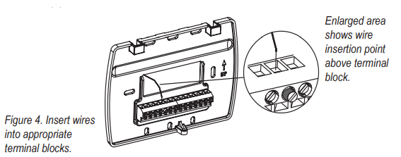
- On the wallplate, insert wires into the terminal blocks that correspond to the system type, then re-tighten each screw for each terminal (see Fig. 4, enlarged area). note: Do not over-tighten screws or use excessive force.
- Assure that no uninsulated wires are exposed: Cap off and place a wire nut on any unused wires. Assure that the attached wires fit into the cavity on the back side of the thermostat.
Part III: Connect Power to the thermostat wallPlate
- Choose from the following options to power the thermostat.
Power options
The T4900 School Series will operate on 24VAC power and/or two AA batteries (both are recommended). Choose from three methods to connect power to the thermostat.
- Batteries only (AA alkaline)
- 24 VAC direct connection only
- 24 VAC with AA battery backup (highly recommended)
- single-transformer system: Connect the common side of the transformer to the “C” screw terminal of the thermostat wall plate. Assure that the metal jumper connects “RC” and “RH.” Connect the power side to the RC/RH and assure that the jumper remains in place.
- two-transformer system: The T4900 School Series is shipped with a jumper connecting terminals RH and RC. If the heating and cooling equipment do not use separate transformers, leave this jumper in place. If separate transformers are required, remove this jumper. With the jumper removed, connect RC to the power side of the cooling transformer. Connect RH to the power side of the heating transformer; then connect both the heating and cooling commons together to terminal C (Common).
Part Iv: Install BatterIes & remove taB
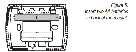
- Insert two AA batteries (included) into the back compartment of the thermostat, where indicated (see Fig. 5).
- Remove the plastic insulator tab from the back side of the thermostat (see Fig. 6).
IMPORTANT: The insulator tab must be removed before setting the real-time clock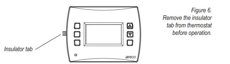
Part v: set the clock, month, anD DaY
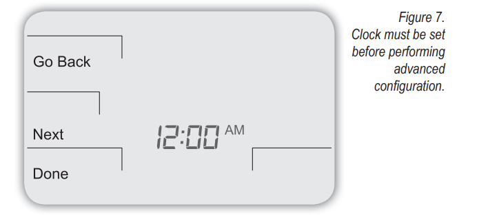
When power is first applied to the thermostat, it will activate the clock display (see Fig. 7). It is recommended that time and day are entered before performing the advanced configuration. Follow the procedure below to set the clock, month, and day.
- Press ▲/ ▼ to select 12 or 24 HR mode, then press Next.
- Press ▲/ ▼to select clock hour, then press Next.
- Press ▲/▼to select clock minutes, then press Next.
- Press ▲/ ▼ to select clock year, then press Next.
- Press ▲/ ▼ to select the current month, then press Next. note: Mo (month) appears.
- Press ▲/ ▼to select the current date. note: Days appear.
- Press Done to finish clock mode.
Part vI: verIFY sYstem settInG Is tUrneD oFF
Note: the fl ashing option is the default selection.
- Press any key to enter the Home Display.
- Press System to enter system settings.
- Press ▲/ ▼to select “Off,” then press Done.
- Press the Fan key to enter fan mode.
- Press ▲/ ▼to select “Auto,” then press Done.
Part VII: PerForm aDvanceD conFIGUratIon
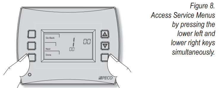
Perform advanced configuration and program the desired schedule before attaching the thermostat to the wall plate. Advanced configuration is done by simultaneously pressing the lower left and lower right keys for about five seconds (see Fig. 8), which gives the user access to Service Menus. Use Table 2 of this Installation Guide to set each desired Service Menu item. Advanced configuration allows the user to configure the thermostat to match the system type and to customize several thermostat settings
Part vIII: moUnt the t4900 onto the wallPlate
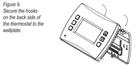
Position the thermostat slightly above the mounted wallplate (see Fig. 9), then secure the hooks on the back side of the thermostat to the hinge pockets on the wallplate. note: the top back side of the thermostat should slip into the hinge pockets easily. Do not use excessive force.
Align the pins on the back side of the thermostat with the terminal blocks on the wallplate. Gently bring down the thermostat onto the wallplate so the pins on the back of the thermostat fi t into the terminal blocks on the wallplate (see Fig. 10). Attach the retaining screw to the underside of the thermostat as shown (see Fig. 10).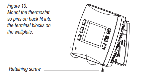
Part IX: verIFY thermostat oPeratIon wIth system tests
System test verification is highly recommended to verify thermostat operation. Follow at least one procedure in the system tests below. Refer to the Service Menus (see Table 2) for more system tests. For all system tests, press next to continue to the following system test, which is the next available Service Menu. Press Done only if finished performing all system tests. Pressing Done exits the Service Menus and turns off all active outputs.
System test maIn oUtPUt (heat)
- On the thermostat, press the lower left and lower right keys simultaneously for about five seconds. Next, Go Back, and Done appear (see Fig. 11).
- Press Next until Service Menu 610 appears in the display. (Default value “00” appears below Service Menu.)
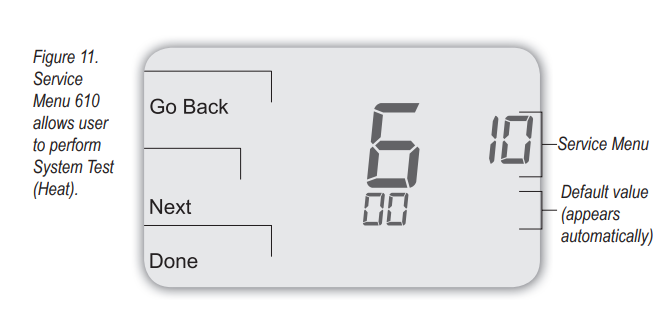
- In Service Menu 610, press ▲/ ▼to select the option “01,” Heat Stage 1 (see Fig.12). note: If 01 is selected, the thermostat will activate the associated output for up to 10 minutes. The user should observe that the fan output (with heat) turns on. The user may also test more stages of heat according to what is available for the system type.
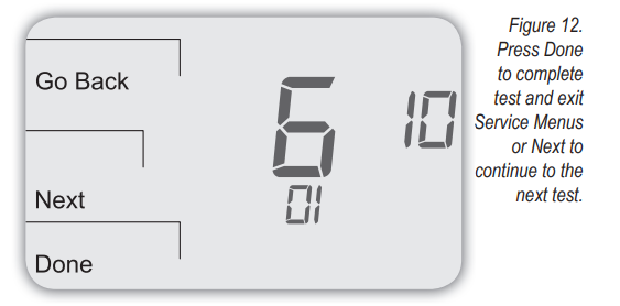
- Press Done to complete the system test and exit the Service Menus. After verifying the system test, the outputs are disabled and the fan will stop.
optional: the user may perform additional system tests by pressing Next to access more service menus (see note below).
System test Fan (optional)
The following instructions assume that the user enters the Service Menus from the Home Display; it does not assume that the user has followed in sequence from the previous section. If continuing from the previous section on this page, skip to Step 2 below.
- On the thermostat, press the lower left and lower right keys simultaneously for about five seconds. note: Next, Go Back, and Done appear (see Fig. 13).
- Press Next until Service Menu 620 appears in the display. (The default value “00” appears below Service Menu.)

- In Service Menu 620, press ▲/ ▼to select the option “01” (to enable fan output).
note: If 01 is selected, the thermostat will activate the associated output for up to 10 minutes. The user should observe that the fan output will turn on.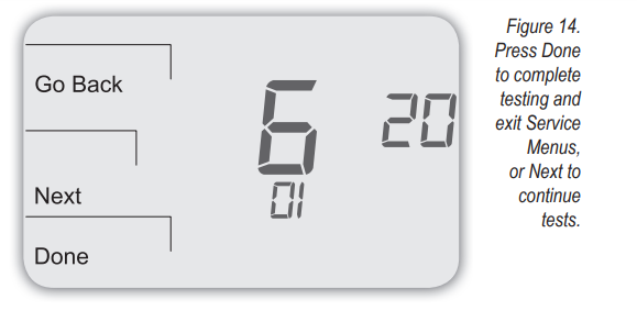
- Press Done to complete the system test. After verifying the system tests, the outputs are disabled.
optional: the user may perform additional system tests by pressing Next. additional system tests include (see table 2): 600, system test main output (cool); 630, system test emergency output; 640, system test economizer
Table 2. Advanced configuration: SERV ICE MEN US
| Menu | Feature | Options | stD. Model DeFaUlt | Description/comments |
| 100* | Schedule Format | 0-4 | 1 | Select the desired schedule format. Select 0-3: Performance PRO, standard format; or select 4: School Schedule format.
0 = nonprogrammable 1 = programmable 2 = 5-1-1 schedule 3 = 5-2 schedule 4 = School Schedule |
| 101 | Daylight-Saving Time | 0,1 | 0 | Select daylight-saving time as it follows the standard format in U.S.: It begins the second Sunday of March at 2:00 AM and ends on the first Sunday of November at 2:00 AM.
0 = Disabled 1 = Enabled (2007 U.S. Format) |
| 110 | System Type | 1-13 | 1 | Select the appropriate system configuration (determines available Service Menus). 1 = 1 Heat/1 Cool Conventional
2 = 1 Heat/1 Cool heat pump 3 = Heat only without fan (2-wire systems) 4 = Heat only with fan 5 = Cool only 6 = 2 Heat/1 Cool heat pump (with auxiliary heat) and Emergency (Em) heat 7 = 2 Heat/2 Cool multistage conventional 8 = 2 Heat/ 1 Cool multistage conventional 9 = 1 Heat/ 2 Cool multistage conventional 10 = 2 Heat/ 2 Cool heat pump (no auxiliary heat) 11= 3 Heat/ 2 Cool heat pump (with auxiliary heat) and Emergency (Em) heat 12 = 3 Heat/ 1 Cool conventional 13= 3 Heat/ 2 Cool conventional |
| 120 | Fan Control (heating) | 0,1 | 0 | 0 = Fossil Fuel: Gas/Oil/Propane heat (equipment controls heating fan) 1 = Electric Furnace (thermostat controls the heating fan) |
| 130 | Changeover valve (B/O terminal) | 0,1 | 0 | 0 = B/O terminal controls valve in cooling 1 = B/O terminal controls valve in heating |
| 140 | Auxiliary Heat | 0,1 | 0 | 0 = Electric backup heat
1 = Fossil fuel backup heat |
| 150 | Backlight | 0,1 | 0 | 0 = Backlight temporarily on
1 = Backlight always on (low intensity, 24V only) |
| 170 | Remote Sensors/ CO2 Sensor | 0-8 | 0 | Select the sensor if used. Contact PECO for information on the T4900 School Series Indoor Remote Zone Sensor.
0 = No Sensor 1 = Indoor Sensor 2 = Outdoor Sensor display only 3 = Outdoor Sensor display and lockout control 4 = Indoor, Outdoor Sensor display only 5 = Indoor, Outdoor Sensor display and lockout control 6 = S3 input configured for CO2 sensor, no indoor sensor. 7 = S3 input configured for CO2 and S1 for indoor sensor. 8 = S3 input configured for CO2 and S1 for outdoor sensor. |
| 172 | System Shutdown (for S1 Terminal) | 0-4 | 0 | A dry contact switch can be connected to S1 input on the T4900 terminal block. When detected in an active state, all HVAC outputs are turned OFF (same as the system off), and Service Indicator (wrench) is displayed on LCD.
0 = Probe, no switch (default) 1 = Shutdown on open 2 = Shutdown on closed 3 = Shutdown on open with remote temperature probe 4 = Shutdown on closed with remote temperature probe |
| 180 | Heat Pump Compressor Lockout | 0-45°F
(-18°C – 7°C) |
0 | If an outside sensor is used, the compressor will be locked out when the outside air temp is below the value selected.0 = None 15°F( -9°C); 20°F (-7°C); 25°F ( -4°C); 30°F ( -1°C); 35°F (2°C); 40°F (4°C); 45°F (7°C) |
| 190 | Heat Pump Auxiliary Lockout | 0- 60°F
(-18°C – 15°C) |
0 | If an outside sensor is used, the auxiliary heat will be locked out when the outside air temperature is above the value selected.
0 = None 40°F (4°C); 45°F (7°C); 50°F (10°C); 55°F (13°C); 60°F (16°C) |
| 230 | Furnace Filter Timer | 0; 10; 30; 60; 90;
120; 365 |
0 | Sets a Furnace Filter Timer reminder; appears on the digital display when the timer expires (if programmed). 0 = Off 10 days; 30 days; 60 days; 90 days; 120 days; 365 days |
| Menu | Feature | Options | stD.moDel DeFaUlt | Description/comments |
| 232 | Enable UV Filter Timer | 0-1 | 0 | Activates the UV Filter Timer. UV Filter timer measures the on-time for Fan output in service of heat, cooling, humidifying, or dehumidifying (Note: UV lamp life varies by manufacturer. PECO is not responsible for lamp life nor for the UV filter.) 0 = UV timer disabled 1 = UV timer enabled |
| 233 | UV Filter Timer Hours | 0-250 | 120
(hundreds of hours) |
Reports UV Filter Timer in hundreds of hours. (Default: Number of hours remaining 120 = 12,000 hours). The service Indicator (wrench) is shown in Default Display when the timer expires. When the UV Filter Timer expires, in Home Display the clock area alternates between the time display and “F 01.” |
| 240 | Number of Program Periods | 2; 4 events | 4 | 2 = 2 events per day
4 = 4 events per day |
| 250 | Clock format | 12 or 24 Hours | 12 | 12 = 12-hour clock mode 24 = 24-hour clock mode |
| 260 | Temperature Format (°F or °C) | 0,1 | 1 | 0 = Celsius
1 = Fahrenheit |
| 270 | Fan Off Delay Heat | 0-99 Seconds | 0 | Select the amount of time (in seconds) that the fan will run after the thermostat heat outputs are turned off. |
| 280 | Fan Off Delay Cool | 0-99 Seconds | 0 | Select the amount of time (in seconds) that the fan will run after the thermostat cool outputs are turned off. |
| 290 | Range Low | 50-90 °F or
10-32°C |
50°F (10°C) | Choose the lowest selectable temperature setpoint value. Only available with Performance PRO settings (see SM 100). |
| 300 | Range High | 50-90 °F or
10-32°C |
90°F (32°C) | Choose the highest selectable temperature setpoint value. Only available with Performance PRO settings (see SM 100). |
| 302 | Teacher Key Heat Setpoint Increase | 0-10 °F | 3 °F | Sets the number of degrees that teacher can increase the temperature above the Occupied Heat Setpoint. |
| 303 | Teacher Key Heat Setpoint Decrease | 0-10 °F | 3 °F | Sets the number of degrees that teacher can decrease the temperature below the Occupied Heat Setpoint. |
| 304 | Teacher Key Cool Setpoint Increase | 0-10 °F | 3 °F | Sets the number of degrees that teacher can increase the temperature above the Occupied Cool Setpoint. |
| 305 | Teacher Key Cool Setpoint Decrease | 0-10 °F | 3 °F | Sets the number of degrees that teacher can decrease the temperature below the Occupied Cool Setpoint. |
| 310 | Setback Low | Off; 50-82°F or 11-27°C | 55°F (13°C) | Select the heat setpoint for setback mode. Only available with Performance PRO settings (see SM 100). 0 = Off
50-82°F (11-27°C) |
| 320 | Setback High | Off; 58-90°F or 11-32°C | 90°F (32°C) | Select the cool setpoint for setback mode. Only available with Performance PRO standard settings (see SM 100). 0 = Off 58-90°F (11-32°C) |
| 330 | Zone Temp Offset | +/-9°F or +/- 4.5°C | 0°F (18 °C) | Adjusts the displayed value; may differ from the actual zone temperature. |
| 340 | Keypad Lockout | 0-3 | 0 | Restricts access to certain features of the device; Service Menu is still available if enabled. 0 = No keypad lockout (Default)
1 = Disables Schedule and System keys 2 = Disables Schedule, System, and Fan keys 3 = Disables all keys |
| 341 | Enable Pin Access | 0,1 | 0 | Applies a 3-digit access code to enter Service Menu 342 0 = Disable
1 = Enable |
| 342 | Set PIN Access Code | 000-999 | 000 | Choose a 3-digit code. |
| 350 | Fan Mode Enable | 1-3 | 3 | 1 = ON: The fan is turned on regardless of demand.
2 = Auto: Fan is turned on according to heating or cooling demand. 3 = ON or Auto: Allows occupant to select either 1 or 2 above. |
| Menu | Feature | Options | stD.moDel DeFaUlt | Description/comments |
| 360 | System Mode Enable | 0-3 | 1 | Allows the ability to determine which system modes the occupant can select. 0 = OFF, Auto
1 = OFF, Heat, Cool, Auto 2 = OFF, Heat, Cool 3 = Heat, Cool, Auto |
| 370 | Economizer/Outside Air Damper Control | 0-4 | 0 | 0 = Off
1 = Time Based Output 2 = Economizer 3 = Continuous Outside Air Damper 4 = Cycled Outside Air Damper (Note: Cycles on demand if CO2 Sensor is applied and configured.) |
| 380 | Minimum Deadband Adjustment | 3-10°F,
1.5-5°C |
3°F | Select a changeover dead band value to prevent short cycling between heating and cooling modes. The value is adjustable to meet various HVAC system requirements. |
| 388 | Restart Occupancy Sensor Count when not-enabled. | 0-2 | 0 | Providing an “occupied” input signal behaves the same as pressing the Teacher key. note: In the event that the teacher button and the occupancy sensor are not in the same state, the Teacher key takes precedence. 0 = No occupancy sensor installed in the system.
1 = Status changes to unoccupied after the time set in the occupied time setting runs out, regardless of occupancy sensor input. 2 = Status remains as occupied as long as the occupancy sensor indicates the room is occupied. |
| 390 | Pre-Occupancy Purge | 0-3 hours | 0 hours | Select to energize the fan for a selected number of hours (0-3) prior to all occupied events. |
| 391 | Adaptive Pre-Conditioning
Schedule (APCS) |
0-1 | 0 | Enables adaptive pre-conditioning schedule (and requires input by user or occupancy sensor after enabled). 0 = Disabled
1 = Enabled; state learns pre-purge and recovery schedule. |
| 392 | Persistence (for APCS) | 1-4 | 2 | Selects the number of weeks that an APCS event shall remain on the schedule. 1 = Event will be removed from the schedule the first time that it does not recur. |
| 395 | Maximum Override Time Limit | 0=Time until next event; or
1-4 hours |
3 | Restricts the duration that a temporary hold can be set. The temporary hold is limited by the maximum amount of time as defined in this Service Menu.
0 = Remainder of time until the next scheduled event. 1 = 1 Hour 2 = 2 Hours 3 = 3 Hours 4 = 4 Hours |
| 396 | School Schedule Default Occupied Duration When Enabled | 0; 0:15; 0:30;
1; 2; 3; 4; 6; 8; 99 |
99 (max.) | Sets the default occupied duration, when the Teacher key is pressed, during School Schedule “enabled” period. 0 = Occupied duration not available to the teacher. The occupied duration is set to the “Max occupied time when enabled” setting.99 = Occupied duration is available to teacher; defaults to “Max occupied duration when enabled” setting. |
| 397 | School Schedule Default Occupied Duration When Disabled | 0:15; 0:30; 1;
2; 3; 4; 6; 8 |
0:15 | Sets the default occupied duration, when the Teacher key is pressed, in School Schedule “Disabled” period. |
| 398 | School Schedule Max. Occupied Duration When Enabled | 0:15; 0:30;
1; 2; 3; 4; 6; 8; 99 |
1 | Sets the maximum occupied duration that the user can enter during the “enabled” schedule period. 99 = Thermostat can be set to remain occupied until the end of the Enabled period. |
| 399 | School Schedule Max. Occupied Duration When Disabled | 0; 0:15; 0:30;
1; 2; 3; 4; 6; 8 |
0:15 | Sets the maximum occupied duration that the user can enter during the “Disabled” schedule period 0 = Thermostat will not become occupied in the Disabled schedule period. |
| 400 | Cycles Per Hour (CPH) Cooling Stage 1 | 0-6 CPH | 3 CPH | Defines the number of cycles per hour for cooling (Stage 1). Select 0 to enable ON-OFF control for Stage 1 cooling. |
| 410 | Cycles Per Hour (CPH) Cooling Stage 2 | 0-6 CPH | 3 CPH | Defines the number of cycles per hour for cooling (Stage 2). Select 0 to enable ON-OFF control for Stage 2 cooling. |
| 420 | Cycles Per Hour (CPH) Heating Stage 1 | 0-12 CPH | 5 CPH | Defines the number of cycles per hour for heating (Stage 1). Select 0 to enable ON-OFF control for Stage 1 heating. |
| 430 | Cycles Per Hour (CPH) Heating Stage 2 | 0-12 CPH | 5 CPH | Defines the number of cycles per hour for heating (Stage 2). Select 0 to enable ON-OFF control for Stage 2 heating. |
| Menu | Feature | Options | stD.moDel DeFaUlt | Description/comments |
| 450 | Cycles Per Hour (CPH) Emergency Heating &
Stage 3 Heat |
0-12 CPH | 5 CPH | Defines the number of cycles per hour for heating. Select 0 to enable ON-OFF control for Emergency Heating & Stage 3 Heat. |
| 460 | Heat Recovery Rate | 0-18°F/Hr
0-10°C/Hr |
5°F/Hr | Defines the rate at which the device achieves the heat comfort setpoint. Select 0 to disable ramp recovery. |
| 470 | Cool Recovery Rate | 0-18°F/Hr
0-10°C/Hr |
5°F/Hr | Defines the rate at which the device achieves the cool comfort setpoint. Select 0 to disable ramp recovery. |
| 480 | Minimum Off Time | 1-10 minutes | 4 minutes | Sets the minimum off time for both the heat and cool output. |
| 482 | Random Start | 0-2 | 0 | 0 = Random start disabled.
1 = Random start enabled, stat powered by batteries only. 2 = Random start enabled, stat powered by AC power, or AC power AND batteries. |
| 483 | Maximum Start Time Offset | 3,5,10,15,30 | 5 | Maximum start time offset. The start time offset will be randomized between 0 and this number of minutes. |
| 484 | Current Start Time Offset | — | — | Displays the randomized start time offset value in minutes. |
| 486 | Evaporator Drain Cycle | 0-1 | 0 | Disables the ventilation output until the drain cycle is complete. Note: The drain cycle lasts about 4 minutes. 0 = Evaporator drain cycle disabled. 1 = Evaporator drain cycle enabled. |
| 490 | Humidity Control Enable
(Select models only) |
0-3 | 0 | Selects how humidity will be controlled. When dehumidify control is enabled, the Y2 terminal becomes dehumidified. Note: If option 3 is selected, Service Menu 491 becomes available.
0 = Disabled 1 = Dehumidify Control 2 = Humidify Control 3 = Dehumidify and Humidify Control |
| 491 | Humidity Deadband | 10-50 | 30% relative humidity (RH) | Selects the dead band in %RH between the humidify and dehumidify setpoints. Note: If option 3 is selected in Service Menu 490, Service Menu 491 becomes available. 10; 20; 30; 40; 50 |
| 500 | Programmable/ Intermittent Fan | 0-2 | 0 | 0 = Disable
1 = Programmable Fan: The fan operates continuously in occupied periods or with demand in unoccupied periods. 2 = Intermittent Fan: The fan operates based on the on and off times set in menus 501 and 502. |
| 501 | Intermittent Fan On Time | 1-60 minutes | 5 minutes | Defines the on-time for the Intermittent Fan. |
| 502 | Intermittent Fan Off Time | 0-60 minutes | 25 minutes | Defines the off time for the Intermittent Fan. Select 0 for the continuous fan. |
| 510 | Power Harvesting Enable
(For use on systems in which a Common “C” power wire is unavailable) |
0-3 | 0 | Options 1-3 draw a small amount of current from the load wire indicated to supplement the battery supply. 0 = No power harvesting is available.
1 = Use Y1 as the battery supplement. 2 = Use W1 as the battery supplement. If Power Harvesting is not compatible with your system, select “0” 3 = Use both Y1 and W1 as the battery supplement (default) to disable. If the thermostat is powered by AC, select only “0” or off. Consult a technician if you have questions. |
| 520 | Default Display Icons | 0-4 | 0 | Select icons that will be displayed in the Default Display screen. 0 = Time, Temp, SP
1 = Time, Temp 2 = Time 3 = Temp 4 = None |
| 530 | Revision | — | — | Displays firmware revision information (for technician); not adjustable. |
| 540 | Factory Default Reset | 0,1 | 0 | Select 1 (enable) to restore the factory default settings for the thermostat. Select 0 to disable. 0 = Disable
1 = Enable Note: Press the “Done” key to complete the process. |
| 541 | Clear APCS Schedule | 0-1 | 0 | 0 = No effect
1 = Clears APCS schedule. The menu resets to 0 after the Done key is pressed. |
| Menu | Feature | Options | stD.moDel DeFaUlt | Description/comments |
| 600 | System Test Main Output (Cool) | 0-2 | 0 | Select an option to activate the fan output for 10 minutes; select 0, Done, or a different Service Menu to disable.
0 = Disable 1= Cool Stage 1 2 = Cool Stage 2 |
| 610 | System Test Main Output (Heat) | 0-3 | 0 | Select an option to activate the fan output for 10 minutes; select 0, Done, or a different Service Menu to disable. Note: Outputs will be activated based on the system configuration.
0 = Disable (Default) 1 = Heat Stage 1 2 = Heat Stage 2 3 = Heat Stage 3 |
| 620 | System Test Fan Output | 0,1 | 0 | Select 0 or 1 to activate the fan output for 10 minutes; select 0, Done or a different Service Menu to disable. 0 = Disable Fan Output
1 = Enable Fan Output Note: Outputs will be activated based on the system configuration. |
| 630 | System Test Emergency Output | 0,1 | 0 | Select 0 or 1 to activate the Emergency output for 10 minutes; select 0, Done or a different Service Menu to disable. 0 = Disable Emergency Output
1 = Enable Emergency Output |
| 640 | System Test Economizer | 0,1 | 0 | Select 1 to activate the Economizer output for 10 minutes; select 0, Done or a different Service Menu to disable. 0 = Disable Economizer Output
1 = Enable Economizer Output |
Creating a PIN access code allows the installer to restrict access to Service Menus. First, PIN access must be enabled in Service Menu 341; second, a three-digit code must be created in Service Menu 342. After these two Service Menus are properly configured, the thermostat requires the user to enter a PIN access code to enter the Service Menus.
- On the thermostat, press the lower left and lower right keys simultaneously for about five seconds. Next, Go Back, and Done appear (see Fig. 15).
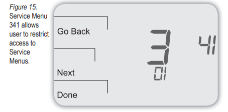
- Press Next until Service Menu 341 (Enable/Disable PIN Access) appears in the display. (Default value “00” appears below Service Menu.)
- In Service Menu 341, press ▲/ ▼to change the digit (flashing) value to “01” (see Fig. 16). note: selecting 01 enables PIn access for the thermostat service menus and selecting it is necessary to show service menu 342.
- Press Next.
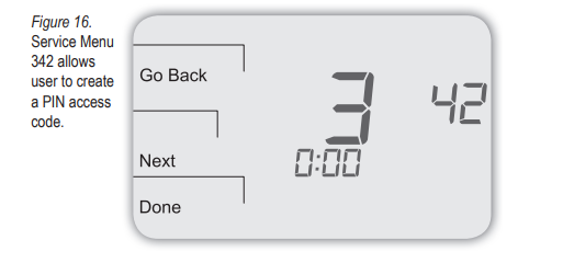
- In Service Menu 342, press ▲/ ▼adjust values and create a three-digit PIN access code. The flashing three-digit code appears in the clock area (see Fig. 16).
note: write down the PIn access code, and keep it in a safe place. - Press Done when finished.
verIFY PIn access code
Enter the PIN access code upon entering the Service Menus. note: Flashing digit is active. Change the digit using the ▲/ ▼keys. The active (editable) digit moves from right to left.
- On the thermostat, press the lower left and lower right keys simultaneously for about five seconds. note: Flashing three-digit code, Next, and Done appear (see Fig. 17).
- Press ▲/ ▼to change the value of the digit furthest to the right, then press Next.
- Press ▲/ ▼to change the value of a digit in middle, then press Next.
- Press ▲/ ▼to change the value of the digit furthest to left, then press Done.
note: After step 4 is complete, the user is allowed access to Service Menus. Next, Go Back, Done, and Service Menu 100 appear.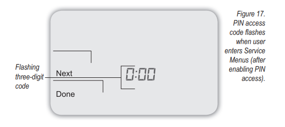
Part XII: t4900 serIes PerFormance Pro sensors
The T4900 School Series is also compatible with PECO sensors, which provide optimal control of the environment and low maintenance. Following are sensor wiring diagrams for temperature averaging and installation instructions for the Indoor Remote Zone Sensor and Outdoor Remote Sensor. (Note: Terminal designations for sensors are shown in Table 4.)
Table 4. termInal DesIGnatIons For sensors
| Peco sensors | model number | terminal | t4900 compatible |
| Indoor Remote Sensor | SP155 | S1 | ■ |
| Outdoor Remote Sensor | P/N 70327 | S1/ S3 | ■ |
| Occupancy Sensor | SB200 | S2 | ■ |
| CO2 Sensor | SC500 | S3 | ■ |
To learn more about the benefits of PECO sensors visit www.pecomanufacturing.com. Or call 1-800-874-8547 to speak with a service representative.
Table 5. Zone sensor maXImUm lenGth anD wIre sIZe
| Distance from Unit to control | recommended wire size |
| 000 – 150 feet (0-46 m) | 22 gauge |
| 151 – 240 feet (46-73 m) | 20 gauge |
| 241- 385 feet (73-117 m) | 18 gauge |
| 386 – 610 feet (118-186 m) | 16 gauge |
| 611 -970 feet (186-296 m) | 14 gauge |
note: Use appropriate wire for outdoor use.
locate & moUnt Peco occUPancY sensor (sB200-001)
Please use the installation instructions for the SB200-001 to mount the PECO Occupancy Sensor SB200-001.
locate & moUnt co2 sensor
The T4900 can be configured for demand-controlled ventilation by using a PECO SC500 CO2 Sensor (see Service Menu 170). For installation of the CO2 Sensor, please see the PECO SC500 CO2 Sensor Installation Instructions. sensor wIrInG For temPeratUre averaGInG (optional) Figure 18. Wiring four SP 155-017 (10K ohm) temperature sensors.

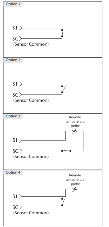
System shUtDown FeatUre (oPtIonal): wIrInG DIaGrams
System shutdown provides the ability to shut down all outputs via S1 Terminal (if enabled), and it may be used with or without the application of a remote temperature probe. A dry contact switch can be connected to the S1 input on the T4900 terminal block. When detected in an active state, all HVAC outputs are turned (same as the system off), and the Service Indicator (wrench) icon is displayed on the LCD. This feature is used for condensate overflow, door/window switch, or service mode detection. note: All diagrams show the dry contact switch in the non-active state. Use Service Menu 172 to configure the input. Select from Options 0-4 in Service Menu 172 ( is the default). Options 0-4 in the following table correspond to the wiring diagram numbers (e.g., Option 1) below.
| Menu | Feature | Options | Default | Description |
| 172 | System | 0-4 | 0 | 0 = Probe, no switch (Default) 1 = Shutdown on open
2 = Shutdown on closed 3 = Shutdown on open with remote temperature probe 4 = Shutdown on closed with remote temperature probe |
| Shutdown | ||||
| (for S1 | ||||
| Terminal) |
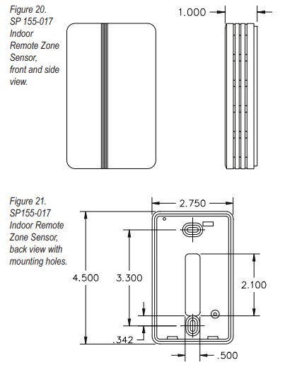
Locate & moUnt Peco InDoor remote sensor (sP 155-017)
Warning
- READ THESE INSTRUCTIONS CAREFULLY BEFORE ATTEMPTING TO INSTALL, OPERATE, OR SERVICE THIS SENSOR.
- Failure to observe safety information and comply with instructions could result in PERSONAL INJURY, DEATH, AND/OR PROPERTY DAMAGE.
- To avoid electrical shock or damage to equipment, disconnect power before installing and use only wiring with insulation rated for full sensor operating voltage.
- This product, when installed, will be part of an engineered system whose specifications and performance characteristics are not designed or controlled by PECO. Review applications and national and local codes to assure that the installation will be functional and safe.
- Do not run low-voltage control wiring in the same conduit with high-voltage wiring.
- Use in indoor applications only.
Installation
- mounting location. Choose a location on an interior wall near the air return grille, about five feet (1.5 m) above floor level, where air circulation is good and temperature is average for the zone.
void mounting the Indoor Remote Sensor in areas such as:- Behind doors
- On outside walls, or any walls with unheated or uncooled areas behind the sensor
- In direct sunlight, or near any source of radiant heat that could affect the temperature measurements
- In line with the discharge air from the unit being controlled.
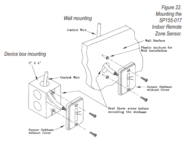
- mount sub base. Remove the Sensor cover from the subbase, and mount the subbase on the wall or in a 2” X 4” device box. Route the wires through the wire access hole in the sub-base (see Fig. 22). Seal the hole in the wall behind the sub-base.
WIRING
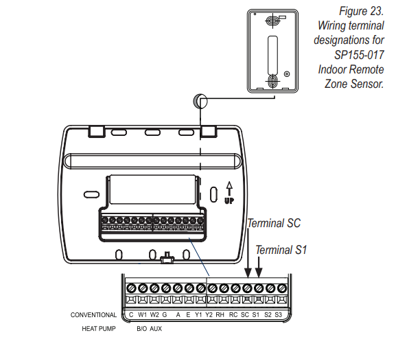
- Run wires. Run wires between the unit control panel and the Sensor sub-base. connect wires. Connect the wiring to the terminals at the thermostat wallplate (S1 and SC) See Fig. 23, below.
Note: See Table 1 for terminal designations for the Indoor Remote Sensor. - replace cover. Place Sensor cover back on the sub-base, and snap it securely into place.
- Go to service menu 170. Select option “01” to enable the Indoor Sensor (see Fig.24).
Caution: Keep wires separate and routed away from any source of noise such as motors, fluorescent lights, and another wiring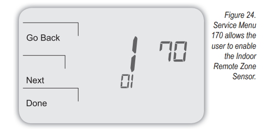
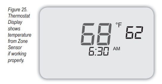
If the Indoor Remote Sensor is functioning properly, the primary display (center) shows the correct temperature taken at the location where Indoor Remote Sensor is currently installed (see Fig. 25).
 Troubleshooting InDoor Remote Sensor
If the thermostat Home Display appears as follows (see Fig. 26), then the Indoor Remote Sensor is not connected properly. Two dashes and the Service Indicator (wrench) appear as the error message.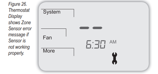
If the Indoor Remote Sensor is not connected properly, check the following:
- Make sure the sensor is wired properly and connected to terminals S1 and SC on the thermostat wallplate (see Table 1, Terminal Designations & System Types).
- If using multiple sensors, make sure the wiring follows diagrams in Sensor Wiring for Temperature Averaging.
- Make sure to select “01” in Service Menu 170.
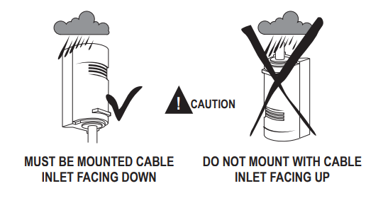
Locate & moUnt Peco oUtDoor remote sensor
Following are instructions on the PECO Outdoor Remote Sensor. Mount the sensor where:
- It can measure true outdoor ambient temperature
- There is good air and circulation
- The surface is fl at
- Wire distance between the sensors cannot be tampered with
- In direct sunlight
- Where hot or cold air blows on the sensor.
- Where discharge line from an outdoor compressor unit, vent, or fan causes inaccurate temperature readings
- Where snow, ice, or debris can cover itDo not mount the sensor in any of the following:
OUTDoor remote sensor InstallatIon
Use the following steps to mount the Outdoor Remote Sensor.
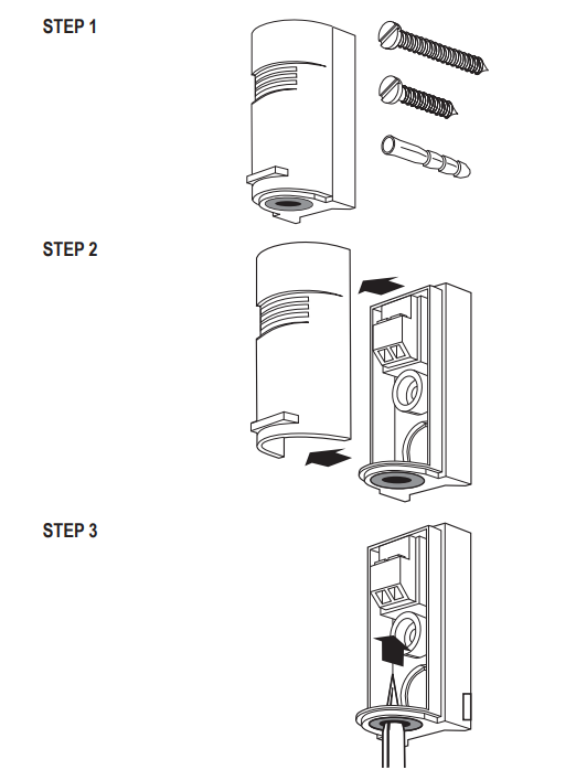
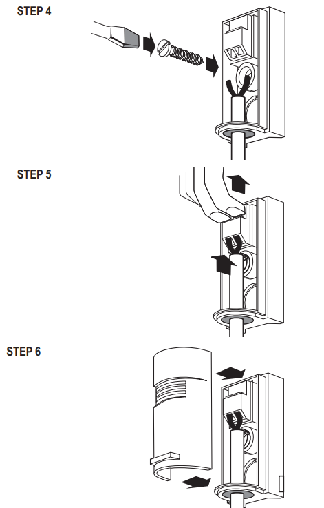
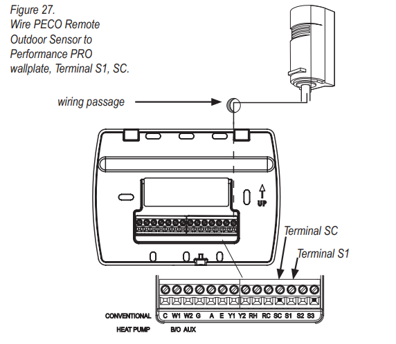
Wire Peco OUtDoor Remote Sensor
- Wire the PECO Outdoor Remote Sensor to Terminal S1 and Sensor Common (SC) on the thermostat wallplate (see Fig. 27).
Note: See Table 1 for terminal designations for the Outdoor Remote Sensor. Assure that Step 6 (previous section) is complete and that the PECO Outdoor Remote Sensor is secure. - Plug the wiring passage using non-hardening caulk or putty.
- Go to Service Menu 170, and select from options 2-5, Outdoor Remote Sensor (see Fig.28).

EconomIZer / TIme-oF-DaY (toD) loGIc
Allow the outdoor or indoor temperature sensor to absorb the air for a minimum of five minutes before taking a reading. See Service Menu 370, which controls Economizer/Outside air damper behavior. Table 6 shows the Economizer/TOD behaviors of available settings (Options include 0-4; 0 = OFF, which disables the Economizer function).
| effective occupancy | cooling Demand | 370 = 1 (toD) | 370 = 2 (economizer) |
| Occupied | N/A | ON Continuously | ON Continuously |
|
Unoccupied |
YES | OFF | ON (Cycles with demand) |
| NO | OFF | OFF | |
| Override | NA | ON Continuously | ON Continuously |
| Demand | system mode | 370 =3 (continuous oa) | 370 = 4 (cycled oa) |
| Heating | Heat | ON Continuously | ON (Cycles with demand) |
| Cooling | Cool | ON Continuously | ON (Cycles with demand) |
| None | OFF | OFF | OFF |
| Heating or Cooling | Auto | ON Continuously | ON (Cycles with demand) |
Heat PUmP temPeratUre lockoUts
Note: heat Pump compressor lockouts (shown below) are only available if an outdoor temperature sensor is applied and confi guard (see table 1).
The options available in Service Menu 140 (below) are dependent on the selected System Type, Service Menu 110.
Dual FUel heat PUmP anD remote oUtDoor remote sensor
In this operation, there is no external fossil fuel kit (dual fuel kit) installed; the thermostat controls this function:
- Choose the correct heat pump application in Service Menu 110, System Type.
- Choose Outdoor Temperature Sensor (Options 3 or 5) for Control Option in Service Menu 170, Remote Sensor.
- Go to Service Menu 140, Auxiliary Heat, and choose “1.”
- Choose an appropriate temperature balance point in Service Menu 180, Heat Pump Compressor Lockout
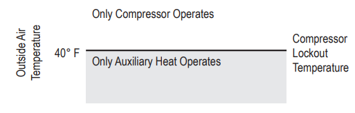
Operation in Heat Mode Above Balance Point (Outdoor Temperature)
When the outdoor temperature is above the selected balance point temperature (Service Menu 180), only the compressor operates and the fan (G Terminal) energizes when the thermostat calls for heat.
Operation in Heat Mode Below Balance Point (Outdoor Temperature)
When the outdoor temperature is below the selected balance point temperature (Service Menu 180), only the Fossil Fuel (auxiliary heat) operates and the fan (G Terminal) does not energize when the thermostat calls for heat.
Fossil FUel aUXIlIarY heat
If Service Menu 140 is set to (fossil fuel Auxiliary Heat), the lockout control is as follows:
 Heat PUmP wIth aUXIlIarY (BackUP) heat anD oUtDoor temPeratUre sensor
- Choose the correct heat pump application in Service Menu 110, System Type.
- In Service Menu 170, Remote Sensor, Choose Outdoor Temperature Sensor (Options 3/5) for Control Option.
- Go to Service Menu 140, Auxiliary Heat, and choose “0.”
- Choose the appropriate balance point in the Service Menu 180, Heat Pump Compressor Lockout.
- Choose Auxiliary Lockout Temperature in Service Menu 190, Heat Pump Auxiliary Lockout.
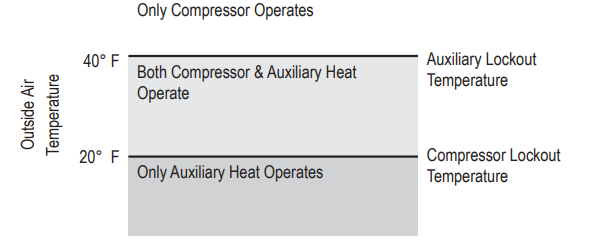
Note: there is a minimum 5°F dead band between compressor and auxiliary heat lockout temperatures.
Operation
When the outdoor temperature is:
- Below the Heat Pump Compressor Lockout Temperature, only the Auxiliary Heat operates.
- Above the Heat Pump Auxiliary Lockout Temperature, only the Compressor operates.
- Between the two temperatures, both the Compressor and Auxiliary Heat operate.
ElectrIc aUXIlIarY heat
If Service Menu 140 is set to (electric Auxiliary Heat) the lockout control is as follows:
Part XII: t4900 school serIes cUstomIZeD settInGs
School Schedule offers one-touch comfort conditioning, making it ideal for educational environments. Smart features like Adaptive Pre-Conditioning Schedule (APCS) simplify HVAC management because APCS adapts to variable occupancy patterns. APCS and School Schedules require input from the Teacher/Override key or an Occupancy Sensor. Enable school scheDUle/teacher keY School Schedule has two scheduled events: Enabled and Disabled (see Table 7 below). The installer may choose the following School Schedule example. The installer may set default occupancy duration limits. The installer may select custom Heat/Cool Setpoints to be applied during the status periods: Occupied1, Unocc1; Occupied2, Unocc2. In routine operation, activation of the School Schedule requires the user to press the Teacher /Override key or the connection and configuration of an occupancy sensor. The following table shows an example of a School Schedule. The school Schedule has two events, Enabled and Disabled, each with occupied and unoccupied settings.
Table 7. school scheDUle eXamPle
| school scheDUle | ||
| enabled | Occupied1 | Unocc1 |
| Start Time: 6:00 AM | Heat Setpoint: 68°F (20°C)
Cool Setpoint: 76°F (24°C) Occupied Duration: 4 HRS (See SM 396) |
Heat Setpoint: 62°F (17°C)
Cool Setpoint: 83°F (28°C) |
| Disabled | Occupied2 | Unocc2 |
| Start Time: | Heat Setpoint: 64°F (18°C) | Heat Setpoint: 58°F (14°C) |
| 4:00 PM | Cool Setpoint: 81°F (27°C) | Cool Setpoint: 85°F (29°C) |
| Occupied Duration: 15 Min. | ||
| (See SM 397) | ||
- Press and hold down simultaneously More and Teacher/Override (lower left and lower right keys). note: Service Menu 100 appears; “01” fl ashes below.
Note: At any time, the user may select Go Back to abort or Done to save settings. - Press ▲/ ▼to highlight option “04,” selecting “School Schedule” format (see Fig. 29).
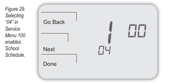
- Press Done. note: If you wish to customize settings, see the next section.
Customise SettInGs For school scheDUle (optional)
Next, select settings for a Heat Setpoint and Cool Setpoint for Occupied1 and Unocc1 status periods to be applied in School Schedule Enabled.
- Press More to view more options.
- Press Schedule to select the days to which settings will be applied.
- Press ▲/ ▼to highlight the day. note: Selected day fl ashes
(Note: Select View to modify an existing event). - Press Edit to apply scheduled events for the selected day(s).
- Press Select Day. note: To select a day press Select Day on flashing day. (Continue pressing Select Day for multiple days; automatically advances to the next day.)
- Press ▲/ ▼to highlight the day(s) to be programmed. note: Selected day(s) for scheduled events must be underlined.
- Press Next. Occupied1 and Unocc1 appear flashing, with the start time shown. note: occupied1 and Unocc1 represent school schedule “enabled” events.
- At the flashing Occupied1 and Unocc1, select Next (see Fig.30).
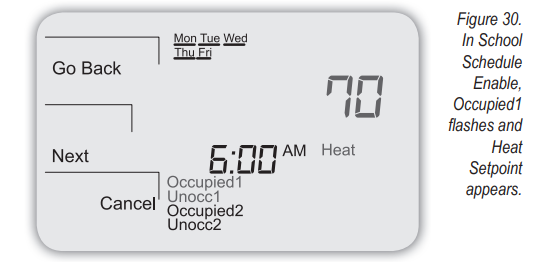
- At the flashing clock, press ▲/ ▼to select a start time for School Schedule Enabled. Note: Start time is adjustable by a quarter-hour.
- Press Next. note: Heat Setpoint appears (flashing) in the upper right (see Fig. 30).
- Press ▲/ ▼to select desired Heat Setpoint for School Schedule Enabled Occupied1.
- Press Next. Cool Setpoint appears.
- Press ▲/ ▼to select a Cool Setpoint.
- Press Next.
- Now select a Heat Setpoint and Cool Setpoint for School Schedule Enabled Unocc1. Repeat steps 12-15 for the Unocc1 settings of Schedule School Enabled.
- Press Next after completing Heat/Cool Setpoints for School Schedule Enable.
- Select Next At the flashing block of Occupied2 and Unocc2.
Note: occupied2 and Unocc2 represent the school schedule “Disabled” events. - At the flashing clock, press ▲/ ▼to select a start time for School Schedule Disabled, Occupied2. note: Start time is adjustable by a quarter-hour.
- Press Next. Heat Setpoint appears (temperature flashing).
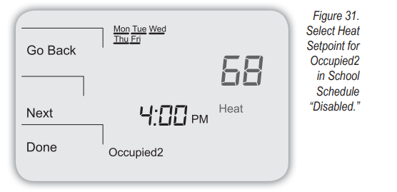
- Press ▲/ ▼to select Heat Setpoint to be applied at the start of the School Schedule Disabled Occupied2 (see Fig. 31).
- Press Next. Cool Setpoint appears.
- Press ▲/ ▼to select Cool Setpoint for Schedule Disabled Occupied2.
- Press Next. Heat Setpoint for Unocc2 appears.
- Now select a Heat Setpoint and Cool Setpoint for School Schedule Disabled Unocc2. Repeat steps 20-22 for the Unocc2 settings of Schedule School Disabled.
- Press Done to save all settings.
restrIctInG DUratIon oF school scheDUle settInGs
The installer may adjust the default duration of the occupied and unoccupied status within Enabled and Disabled events, and adjust the maximum occupied time for which settings can be applied (see Table 2). If you wish to program these settings, continue as follows:
- To program the default occupied period in which School Schedule Enabled settings apply when the Teacher/Override key is pressed, see SM396, Default Occupied Duration When Enabled.
- To program the default occupied period in which School Schedule Disabled settings apply when the Teacher/Override key is pressed, see SM397, Default Occupied Duration When Disabled.
- To program, the maximum occupied duration that the user can enter during the Enabled event, see SM 398, Max. Occupied Duration When Enabled.
- To program, the maximum occupied duration that the user can enter during the Disabled event, see SM 399, Max. Occupied Duration When Disabled.
- To program the number of degrees that the Heat Setpoint and Cool Setpoint may be increased and decreased, upon pushing Teacher/Override, see SM 303-SM 305.
Enable aDaPtIve PreconDItIonInG scheDUle
Adaptive Pre-Conditioning Schedule (APCS) is intended to pre-condition a room for occupancy based on weekly routines. An optional feature of School Shedule, APCS helps educational facilities meet clean air quality standards. The installer must select the number of weeks an occupancy event remains in memory (SM 392), the number of hours prior to occupancy to apply pre-purge (SM 390), and the heat/cool recovery rate (SM 460/470). APCS is only initiated by occupancy. A user must press the Teacher key or an Occupancy Sensor must be applied. Thereafter, APCS applies pre-purge and heat/cool recovery settings before the weekly occupancy event. APCS continues to adjust to a user’s weekly routine based on whether occupancy is initiated within a consistent timeframe. APCS learns occupancy routines quickly and forgets them slowly.
- Press, and hold down simultaneously the More and Teacher /Override (lower left and lower right) keys to enter Service Menus. Service Menu 100 appears.
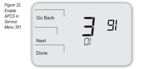
- Press Next to go to Service Menu 391.
- Press ▲/ ▼to select “01” to enable.
- Press Done when finished.
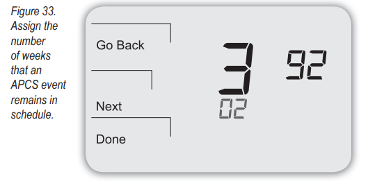
- Now assign the number of weeks that an APCS event will remain in the schedule. Advance to Service Menu 392. The default option is two (2) weeks. Note: APCS utilizes the number of weeks that the start time of an occupancy event remains in the schedule.
- Select (0-4) the number of weeks that the start time of an occupancy event remains in the schedule (see Fig.33).
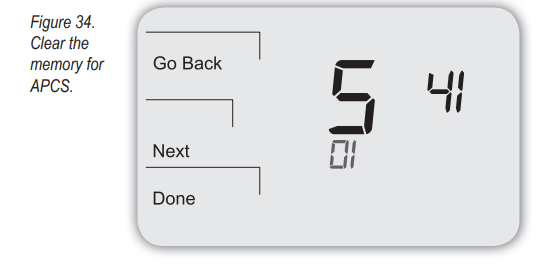
- Optional: To clear the APCS schedule, advance to Service Menu 541 (see Fig. 34).
- Press ▲/ ▼and select “01,” then press Done. The menu resets to “0” after the Done key is pressed.
Note: In order for APCS to function properly, assure that:
- Occupancy Sensor is enabled —if used for application (see SM 388)
- School Schedule format is applied to the thermostat (see SM 100)
- Pre-Occupancy Purge sets the number of hours prior to occupied events (see SM 390)
Enable keYPaD lockoUt
Keypad lockout blocks access to certain features of the thermostat but allows access to the Service Menus. After the keypad lockout is enabled, the padlock icon will appear. Three levels of Keypad Lockout are available (see SM 340). note: If option 3 is selected, all keys will be disabled except for the key combination used to enter into Service Menus (for restricting access to the Service Menus, see SM 341, PIN Access). In the following example, the installer will enable Keypad Lockout, Option 3, which disables all key functions, except for access to the Service Menus.
- Press, and hold down simultaneously the More and Teacher /Override (lower left and lower right) keys to enter Service Menus. Service Menu 100 appears.
- Press Next to go to Service Menu 340.
- In Service Menu 340, select Option “03,” which disables all keys (see Fig.35).
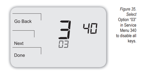
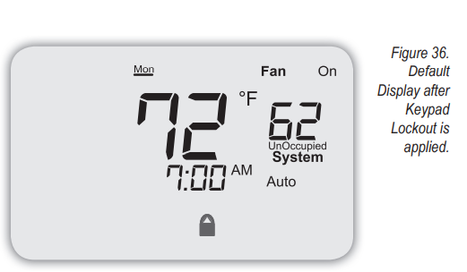
- Press Done. note: After the above steps are complete, the Default Display is shown, in addition to a padlock icon at the bottom (see Fig. 36).
- To reset Keypad Lockout to the default setting (0, No Keypad Lockout), press and hold down simultaneously More and Teacher /Override (lower left and lower right) keys to enter Service Menus. Service Menu 100 appears.
- Press Next to go to Service Menu 340 (see Fig. 37).
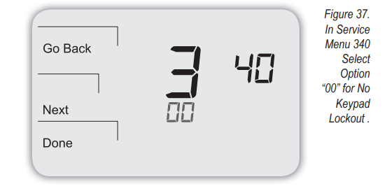
- In Service Menu 340, select Option “00,” which enables “No Keypad Lockout.”
Table 3. TroUBleshootInG & FreqUentlY askeD QuestIons
| symptom | Potential cause(s) | solution |
| If the display screen is blank | Thermostat is not being powered | • Check to assure connection between Common (C) and (RC) for 24 VAC.
• Check to assure that the metal jumper connects “RC” and “RH” (on a single transformer system only). • Check to assure AA batteries are installed properly and are charged. |
| Default Display is set to “4” (None) | • Check Service Menu 520. | |
| If the display screen is blank AND the system is running AC power only | Power harvesting is enabled without battery support | • Install batteries and select “0” (disabled) in Service Menu 510 (to disable Power Harvesting). |
| If keys do not allow manual entry | Keypad Lockout may be enabled | • Access Service Menu 340. Within this menu, select option “0” to assure there is no keypad lockout (so manual entry is enabled). |
| If Service Indicator (wrench) is on | Remote temperature sensors may not be installed correctly or may be damaged. | • Check to assure that the remote temperature sensor is connected properly. Ensure that the system uses PECO-approved sensor(s). |
| • Check range limits and dead band (see Service Menus 290, 300, 380). | ||
| Keypad is locked | • See the item above | |
| If no heating or cooling is running, but there is a call for heat or cool (Heat/Cool appears on display) in Auto mode | Heating or cooling equipment is not operating | • Check Service Menu 110 to assure that the correct option is selected to match the system type.
• Check wiring, using output tests to verify (see Service Menus 600, 610, 620, 630, 640). |
| If heating and cooling system doesn’t respond | System type selection is incorrect | • Check Service Menu 110 to assure that the correct option is selected to match the system type. |
| If heating and cooling equipment are running at the same time | System type selection is incorrect | • Check Service Menu 110 to assure that the correct option to match the system type is selected. |
| Heating and cooling wires are shorted together | • Separate the heating and cooling wires, using output tests to verify (see Service Menus 600, 610, 620, 630, 640). | |
| Heat does not turn on (Heat is on continuously on display) | • Heating equipment failure
• Loose or broken wire connection between heating equipment and thermostat |
• Check for 24 VAC at the equipment on the secondary side of the transformer between the Power for Heating (RH) and the Common (C).
• Check to assure 24 VAC connection between heat terminal (W1) and transformer Common (C). If 24 VAC is present, the thermostat is functional. Check heating equipment to find cause of failure. If voltage is not present, check wire connection between the heating equipment and the thermostat. |
| If the Demand Indicator light is red | • Heating is occurring | • No action is required. |
| If the Demand Indicator light is green | • Cooling is occurring | • No action is required. |
| If the Demand Indicator light is flashing | • An error has occurred
• Remote sensor may be malfunctioning |
• Check remote sensor wiring.
• Verify that the sensor(s) are PECO supported products. |
| If the heat pump issues cool air in heat mode or warm air in cool mode | • Changeover valve (B/O terminal) is not configured to match the heat pump | • Check Service Menu 130 to assure that the changeover valve (B/O terminal) is set to properly match the heat pump. |
| Cooling does not turn on (Cool is on display) in Auto mode | Cooling equipment failureLoose or broken wire between cooling equipment and thermostat | • Check for 24 VAC at the equipment on the secondary side of the transformer between the Power for Cooling (RC) and the Common (C).
• Check to assure 24 VAC connection between the cool terminal (Y1) and transformer Common (C). If 24 VAC is present, the thermostat is functional. Check cooling equipment to find the cause of failure. If voltage is not present, check the wire connection between the cooling equipment and the thermostat. |
| If the fan does not turn on when there is a demand for heat | • System type may be incorrect | • See Service Menu 110 and assure that the correct option is selected. |
| Fan control may be incorrect | • See Service Menu 120 and assure that the correct option is selected. | |
| If the heating system is running in the cool mode | System type selection is incorrect | • Check Service Menu 110 to assure that the correct option is selected to match the system type. |
| If the heating equipment does not turn off and the heat temperature setting is set below room temperature | Heating equipment is not a heat pump but the system type selected is a heat pump | • Check Service Menu 110 to assure that the correct option is selected to match the system type. |
| If the user cannot select the system setting for cool | System type is set to Heat only or Heat only with fan | • Check Service Menu 110 to assure that the correct option is selected to match the system type. |
| If the user cannot select the system setting for heat | System type is set to Cool only. | • Check Service Menu 110 to assure that the correct option is selected to match the system type. |
© COPYRIGHT 2011 PECO, INC. ALL RIGHTS RESERVED. Performance PRO and School Series are trademarks and PECO is a registered trademark of PECO, Inc. The PECO logo is a trademark or servicemark of PECO, Inc.
REFERENCE:
DOWNLOAD MANUALS:
Peco T4900 Programmable Thermostat Installation Guide
OTHER MANUALS:
Peco T4900 Programmable Thermostat Operating Manual
![]()
Leave a Reply