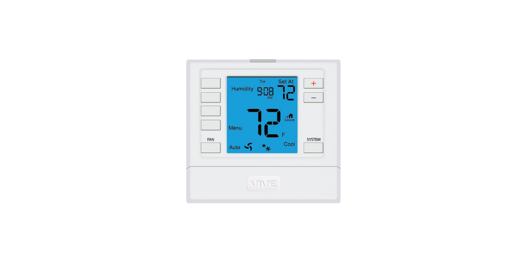
Vive Comfort TP-N-771 Non-Programmable Thermostat
Vive Comfort
P.O. Box 3377
Springfield, MO 65804
Toll Free : 888-776-1427
Web: www.vivecomfort.com
Hours of Operation: M-F 9AM – 6PM Eastern
Thermostat Application Guide
| Description | |
| Gas or Oil Heat | Yes |
| Electric Furnace | Yes |
| Heat Pump (No Aux. or Emergency Heat) | No |
| Heat Pump (With Aux. or Emergency Heat) | No |
| Multi-Stage Systems | No |
| Heat Only Systems | Yes |
| Heat Only Systems – Floor or Wall Furnace | Yes |
| Cool Only Systems | Yes |
| Millivolt | Yes |
Specifications
- The display range of temperature … 20˚F to 99˚F (-7˚C to 37˚C)
- The control range of temperature…. 25˚F to 99˚F (-4˚C to 37˚C)
- Swing (cycle rate or differential) ……
Heating is adjustable from 0.2˚ to 2.0˚
Cooling is adjustable from 0.2˚ to 2.0˚ - Power source …………………………………….18 to 30 VAC, NEC Class II, 50/60 Hz for hardwire
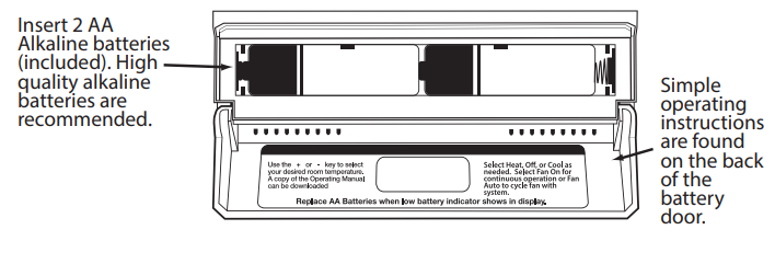
- Battery power from 2 AA Alkaline batteries
- Operating ambient …………………………. 20˚F to +105˚F (-7˚C to +41˚C)
- Operating humidity ………………………… 90% non-condensing maximum
- Dimensions of thermostat …………….. 4.7”W x 4.4”H x 1.1”D
Power Type
Battery Power
Hardwire (Common Wire)
Hardwire (Common Wire) with
Battery Backup
A trained, experienced technician must install this product.
Carefully read these instructions. You could damage this product or cause a hazardous condition if you fail to follow these instructions.
Wall Locations
The thermostat should be installed approximately 4 to 5 feet above the floor. Select an area with average temperature and good air circulation.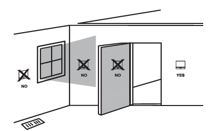
Do not install thermostat in locations:
- Close to hot or cold air ducts
- That are in direct sunlight
- With an outside wall behind the thermostat
- In areas that do not require conditioning
- Where there are dead spots or drafts (in corners or behind doors)
- Where there might be concealed chimneys or pipes
Installation Tip
Pick an installation location that is easy for the user to access. The temperature of the location should be representative of the building.
Subbase Installation
- Horizontal Mount
- Vertical Mount
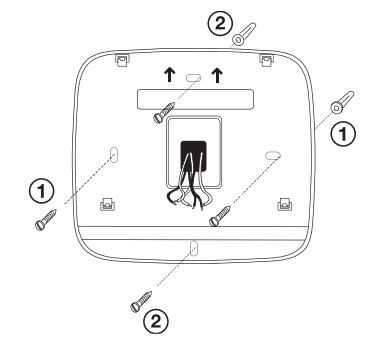
For vertical mount put one screw on the top and one screw on the bottom.
For horizontal mount put one screw on the left and one screw on the right.
Installation Tip: Electrical Hazard
Failure to disconnect the power before beginning to install this product can cause electrical shock or equipment damage.
Mercury Notice All of our products are mercury-free. However, if the product you are replacing contains mercury, dispose of it properly. Your local waste management authority can give you instructions on recycling and proper disposal.
Installation Tips
Mount Thermostat
Align the 4 tabs on the subbase with corresponding slots on the back of the thermostat, then push gently until the thermostat snaps in place.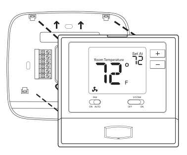
Battery Installation
Battery installation is recommended even if thermostat is hardwired (C terminal connected). When thermostat is hardwired and batteries are installed, the thermostat will activate a compressor delay of 5 minutes when the thermostat detects a power outage from the hardwired power supply.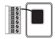
Important: High quality alkaline batteries are recommended. Rechargeable batteries or low quality batteries do not guarantee a 1-year life span.
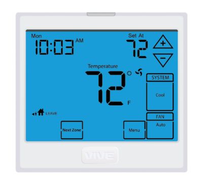
Getting to know your thermostat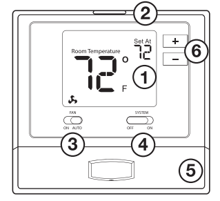
- LCD
- Glow in the dark light button Fan switch
- System switch
- Easy change battery door
- Temperature setpoint buttons
Removing The Private Label Badge
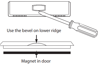
About The Badge
All of our thermostats use the same universal magnetic badge. Visit the company website to learn more about our free private label program.
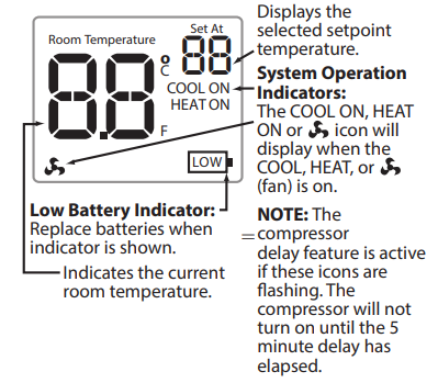
Important The low battery icon is displayed when the AA battery power is low. Whenever the thermostat detects low battery voltage from the AA batter-ies, the low battery icon will begin flashing on the screen ftor 21 days (if the batteries are not changed). If the batteries are not changed 22 days after the thermostat detects low battery voltage, the thermostat screen will only show the flashing battery icon until buttons are pressed. If the batteries are not changed 43 days after the thermostat detects low battery voltage, the thermostat screen will only
show the flashing battery icon until buttons are pressed and the set points will offset to 85°F/29°C in cooling and 55°F/13°C in heating. At this stage, set point changes can be made temporarily but, the set points will change back to defaulted values after a 4-hour period. The thermostat will continue to perform this low battery flashing, temperature offset condition until the internal voltage threshold is reached. When the thermostat internal voltage threshold is reached, all relays will be opened and the thermostat will become inoperable until new batteries are installed.
Wiring
Caution: Electrical Hazard
Failure to disconnect the power before beginning to install this product can cause electrical shock or equipment damage.
Warning: All components of the control system and the thermostat installation must conform to Class II circuits per the NEC Code.
- If you are replacing a thermostat, make note of the terminal connections on the thermostat that is being replaced. In some cases the wiring connections will not be color coded. For example, the green wire may not be connected to the G terminal.
- Loosen the terminal block screws. Insert wires then retighten terminal block screws.
- Place non-flammable insulation into wall opening to prevent drafts.
Installation Tip
Do not overtighten terminal block screws, as this can damage the terminal block. A damaged terminal block can keep the thermostat from fitting on the subbase correctly or cause system operation issues.
Max Torque = 6in-lbs.
Terminal Designations
- RH Transformer power for heating
- RC Transformer power for cooling
- Y/W Heat relay or Compressor relay
- C Common wire from system transformer
- G Fan relay
Warning: Do NOT remove the jumper pin. The jumper pin is required for both heating and cooling applications.
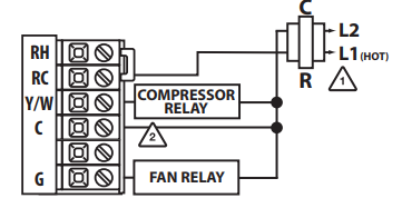
Wiring Diagrams
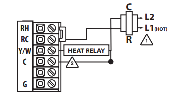
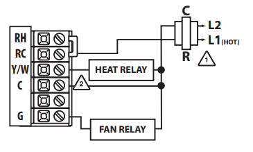
- Power supply
- Optional 24 VAC common connection when thermostat is used in battery power mode
Wiring Tips
C Terminal
The C (common wire) terminal does not have to be connected when the thermostat is powered by batteries.
Wire Specifications
Use shielded or non-shielded 18-22 gauge thermostat wire.
Typical Heat Only System
Typical Heat Only System With Fan
Typical Cool-Only System
Technician Setup
Tech Setup Steps
- Select OFF with the System Switch.
- Hold down the + and – buttons together for 3 seconds.
- Use the + and – button to change setting for that step, and the glow in the dark button to move from one step to another. Toggle system switch when done.
|
Room Temperature Calibration |
This feature allows the installer to change the calibration of the room temperature display. For example, if the thermostat reads 70˚ and you would like it to read 72˚ then select +2. | CA
O 0F |
You can adjust the room temperature display to read up to 4˚above or below the factory-calibrated reading. |
0˚F |
|
Compressor Short Cycle Delay |
The compressor’s short cycle delay prevents the compressor from switching on and off too often. | Cd | Selecting “ON” will not allow the compressor to be turned on for 5 minutes after the last time the compressor was switched off. Select “OFF” to remove this delay. |
ON |
|
F or C |
Select F for Fahrenheit temperature read out or select C for Celsius read out. | FC
F |
F for Fahrenheit C for Celsius | F |
|
Heat or Cool |
This feature allows the installer to configure the thermostat for Heat only or Cool only operation.
Note: When in COOL mode ELEC switch must be turned on. Warning: Compressor may freeze if the FAN is not ON, make sure you are in ELEC mode while in COOL mode. |
HE |
Heat or Cool
HE – HEAT CO – COOL |
HE |
Selecting Heat or Cool
- Select ON with the System Switch.
- Hold down the + and – buttons together for 3 seconds.
- Use the + and – button to change setting for that step, and the glow-in-the-dark button to move from one step to another. Toggle the system switch when done.
| Tech Setup Steps LCDWill Show | Adjustment Options Default | |||
|
Swing |
The swing setting, often called “cycle rate”, “differential” or “anticipation” is adjustable. A smaller swing setting will cause more frequent cycles and a larger swing setting will cause fewer cycles. (reference the Technician Setup Menu steps above for how to enter this Menu) | SG
0.4 |
The swing setting is adjustable from 0.2˚ to 2˚. For example: A swing setting of 0.5 will turn the system on and off at approximately 0.5˚ away
from the setpoint. Only the swing for the selected mode (Heat or Cool)is displayed in the menu. |
0.4 |
|
Temperature Setpoint Limit |
This feature allows you to set a maximum heat setpoint valve. The setpoint temperature cannot be raised above this value. You can also set a minimum cool setpoint value if in cool mode. | 25
SL 99 SL |
Use the or key to select the maximum heat setpoint or the minimum cool depending on the selected mode (Heat or Cool). | 25
99 |
Gas or Electric Setup
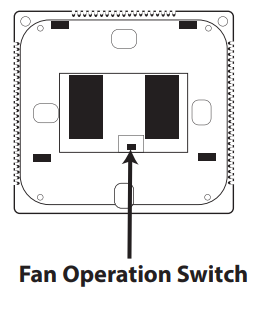
Electric: For installations that control the fan during a call (for cool or heat), move the fan operation switch to the ELECTRIC position.
Gas: For installations that do NOT control the fan during a call (for cool or heat), move the fan operation switch to the GAS position.
NOTE: When in COOL mode the FAN icon will flash if the switch is in GAS mode. This flash is a reminder to select ELEC to engage the fan with the compressor.
Reference
Download Manual:
Vive Comfort TP-N-771 Non-Programmable Thermostat Instruction Manual
OTHER MANUALS
Vive Comfort TP-N-771 Non-Programmable Thermostat Operational Manual
Vive Comfort TP-N-771 Non-Programmable Thermostat Instruction Manual
Leave a Reply